Hawkes P.W., Spence J.C.H. (Eds.) Science of Microscopy. V.1 and 2
Подождите немного. Документ загружается.

1030 M. Amrein
In the following section, AFM and its elements are described. The
basics for preparing macromolecular and cellular samples are then
described. Finally, a few select examples highlight AFM experiments,
in which a combination of imaging with sample manipulation has been
used to understand macromolecular or cellular function. A compre-
hensive review all AFM applications in the life sciences is beyond the
scope of this chapter.
2 Instrumentation and Imaging
2.1 Introduction
In AFM, the topology of the sample is traced by a sharp stylus that is
scanned line by line over the sample. For most setups, the stylus is
sitting at the free end of a cantilever spring. Every elevation on the
sample causes the stylus to move up and bend the cantilever upward
and every depression makes the lever move down. Stylus and cantile-
ver are usually microfabricated from silicon or silicon nitrite. The can-
tilever is typically a fraction of a millimeter long and a few micrometers
thick. The softer the specimen, the softer the cantilever spring should
be for it to trace the sample surface rather than deform it. The shape of
the stylus is crucial too. It may be tetrahedral or extended, with a high
aspect ratio, depending on need. The radius of curvature at the apex
of the stylus may be as small as 2 nm (the apex of the stylus is also
referred to as the tip) (Figure 16–5).
Accurate measurement of the defl ection of the cantilever is the basis
for accurate measurement of the sample topology. It also allows proper
control of the loading force of the stylus onto the sample. It turns out
that this latter aspect is particularly important in life science applica-
tions of AFM (see below). The fi rst AFMs used an STM behind the
cantilever to measure the defl ection. Defl ection has also been mea-
sured by the change in electrical capacitance between the cantilever
and a reference electrode, or by means of a piezoresistor integrated
with the cantilever (Tortonese et al., 1993). Most AFMs now use an
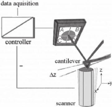
Figure 16–5. The elements of
an AFM.
Chapter 16 Atomic Force Microscopy in the Life Sciences 1031
optical pointer to measure cantilever defl ection. This detection system
is fully adequate as it poses no limitation to AFM resolution.
In the optical pointer detection, a laser beam is focused onto the back
of the free end of the cantilever (Figure 16–5). The laser beam is then
refl ected off the cantilever onto a four-segment photodiode. Prior to
imaging, the four-segmented laser diode is moved until all four seg-
ments are equally illuminated. For imaging, the stylus is then loaded
onto the sample. This causes the free end of the cantilever to bend
upward and the laser beam now illuminates the two upper segments
more strongly. The signals from the two upper segments of the diode
are compared to the two lower segments [(A + B) − (C + D)] to derive
the amount of defl ection of the lever in the z direction. The load is
preset by the user, depending on the application and is related to the
defl ection of the cantilever:
F = c ⋅ ∆S
∆S is the defl ection in the z direction and c is the spring constant of
the cantilever. The force is typically selected within the range of less
than 100 pN to a few nanonewtons, depending on the application.
In operation, the cantilever is defl ected from the preset value by the
sample topology and the refl ected laser beam is moved up or down.
The original defl ection is then restored via a feedback loop by a motion
of the scanner perpendicular to the sample plane (referred to as the z
direction). The position of the scanner with respect to the tip is recorded
and used as the AFM topographical image.
Torsion of the cantilever may also occur during scanning, when the
tip is experiencing friction with the sample. When the cantilever is
becoming twisted, the laser beam is moved sideways. The amount of
torsion and, hence, friction is then derived from comparison of the
signals from the two right and two left segments of the photodiode
[(A + C) − (B + D)]. Maps of local friction are used to reveal materials
contrast in addition to the topographical image.
In dynamic AFM modes, the cantilever is oscillated and the ampli-
tude and phase of the oscillation are monitored using the laser signal
on the photodiode rather than a static defl ection.
An AFM does not necessarily need to be based on a cantilever at all.
In an instrument combining AFM topographical imaging with near-
fi eld optical imaging (the scanning near-fi eld optical microscope,
SNOM or NSOM), a tapered optical fi ber is used as the stylus in most
current instruments. It is oscillated parallel to the sample. Dampening
of this oscillation is used as the feedback signal. In another alternative
setup to the cantilever-based AFM, the sample is mounted on the
membrane of an electret microphone and the output of this micro-
phone is used for feedback. This setup performs equally well as the
more traditional cantilever setup (Figure 16–6).
In addition to a highly sensitive probe, AFM depends on a precise
scanner. The scanner is attached either to the probe or the sample. It
allows the sample to be scanned with respect to the stylus in the plane
of the sample (referred to as the x,y plane) and adjusting the relative
height of the sample and the probe (referred to as the z direction) with
1032 M. Amrein
subatomic precision (Amrein et al., 1997). AFM scanners are made of
voltage-driven piezoceramic elements.
AFM imaging is a mechanical process, usually operated in a closed
feedback loop. Even an apparently crisp, high-resolution topographical
image need not necessarily refl ect the true sample topography. The
faithfulness of the topographical images depends on the properties of
the feedback loop, the tip and sample geometries, and on how much
the sample deforms upon imaging. Eventually, the accuracy of the
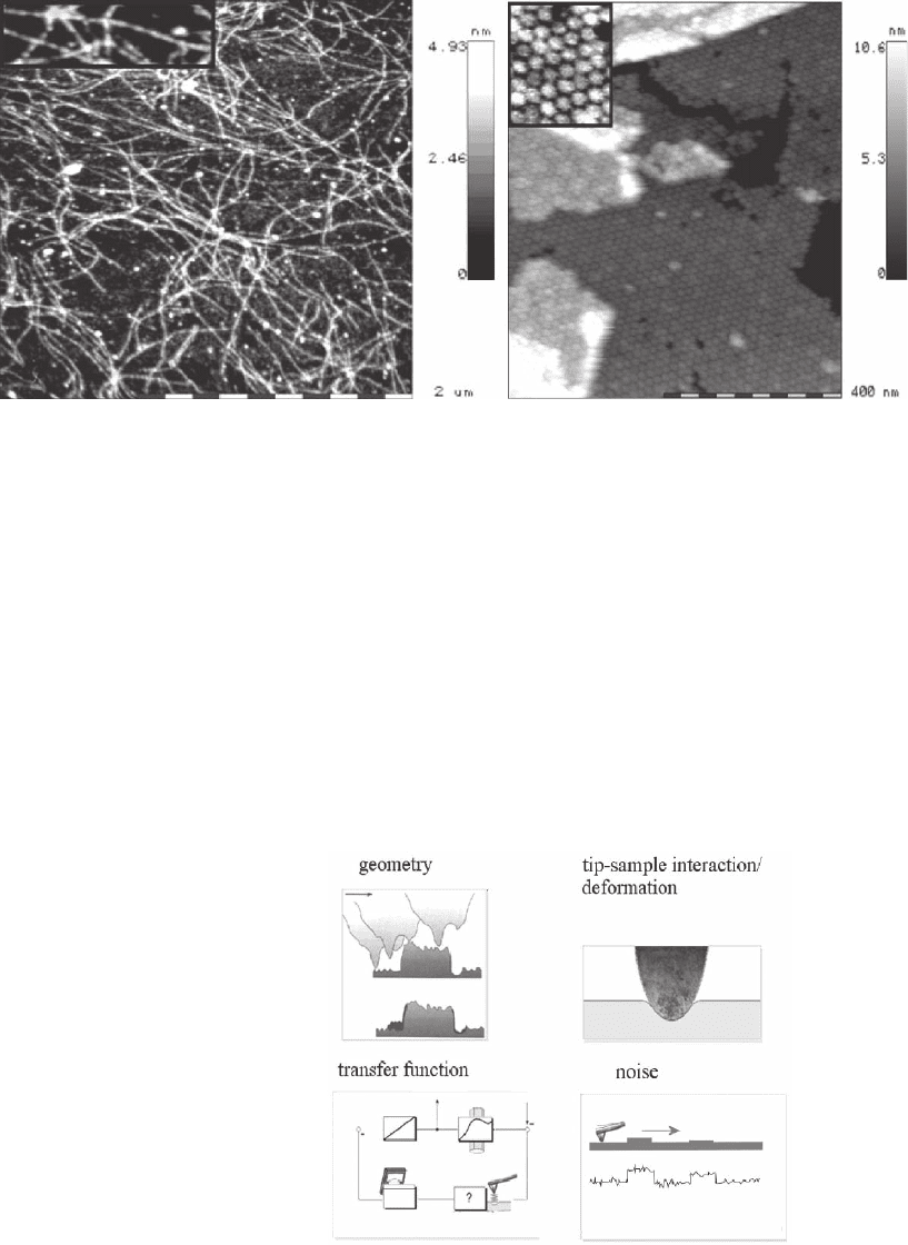
topographical images is limited by noise (Figure 16–7). Each of these
aspects is discussed below. Also discussed is how development of
AFM technology might lead to improved instrument performance.
Figure 16–6. Actin fi laments (left) and an archebacterial S-layer (HPI-layer, right) imaged with an
AFM based on an electret sensor, rather than a cantilever sensor (Schenk et al., 1994, 1996).
Figure 16–7. The faithfulness of an AFM topographical image depends on the
sample and tip geometries, the sample deformation, the quality of the mechan-
ical feedback loop of the instrument, and noise.
Chapter 16 Atomic Force Microscopy in the Life Sciences 1033
2.2 Geometry of the Stylus
When the stylus moves over a sample, the effective point of contact of
the tip with the sample also changes. The topographical image is, col-
loquially speaking, convoluted with the tip geometry. The early days
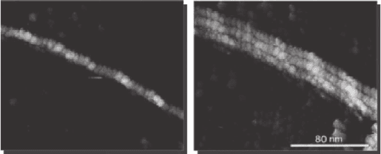
of AFM (and STM) were plagued by ill-characterized tips. Multiple
whiskers created images that contained the same object multiple times
(Figure 16–8). For a blunt stylus, each prominent object of the sample
resulted in a local image of the tip itself rather than the local sample
topology, and the overall appearance of such images has been cloudy.
Because both the tip geometry and the sample topology matter, high-
resolution images were sometimes obtained with an apparent blunt tip
for very fl at samples. This is because even the bluntest of tips has a
rough surface, being covered with fi ne asperities.
Commercially available cantilevers now come with a well-
characterized stylus and the apex may have a very small radius of cur-
vature. The shape of the stylus needs to be selected with the sample in
mind. Biological membranes or two-dimensional arrays of proteins with
little overall height variations, for example, are well imaged by a pyramid-
shaped stylus that ends in an apex of small radius of curvature, whereas
a sample with prominent topology with steep fl anks needs to be scanned
by an elongated, needle-like stylus of high aspect ratio. During imaging,
even a well-characterized, sharp stylus may become mechanically
damaged or may pick up contaminate that renders it blunt. In these
cases, the probe needs to be cleaned (e.g., by washing in ultrapure water,
containing a detergent). If not successful, it has to be replaced.
When selecting an appropriate stylus, not only the expected sample
topology must be considered. The sample compliance is an equally
important aspect as a sharp tip may strongly deform a soft sample.
This aspect is described below.
2.3 Tip–Sample Interaction
The tip–sample interactions need to be considered carefully, because
they infl uence critically the success of the experiments. In AFM, most
of the time the stylus is loaded onto the sample either intermittently
(referred to as intermittent contact mode or tapping mode) or con-
Figure 16–8. A single active fi lament, imaged with a single tip (left) and after
the tip has become a triple tip (right).
1034 M. Amrein
stantly (contact mode; see below). This is achieved by approaching the
probe and sample and bending the cantilever until the desired loading
force is achieved.
In addition to the loading force, exerted by the cantilever spring,
there are additional forces F
StSa
acting between the sample and the
stylus (see below). They may be repulsive or attractive. An attractive
force makes the effective load of the tip onto the sample greater than
what would be assumed from the bending of the cantilever. A repul-
sive force that acts prior to physical contact reduces the effective load
of the tip onto the sample. The total loading force of the tip onto the
sample becomes
F = c ⋅ ∆S + F
StSa
where ∆S is the defl ection of the cantilever and c is the spring constant
of the cantilever.
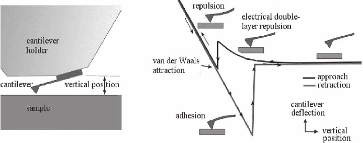
Evaluating these interactions may be pursued by acquiring force-
versus-distance curves (referred to also as “force spectroscopy”).
Thereby, the tip is approached to the sample and the defl ection of the
cantilever recorded as a function of the vertical position of the scanner
with respect to the sample. The defl ection of the cantilever can then be
converted into a force using the spring constant of the lever (Figure
16–9).
2.3.1 Sample Deformation
When physical contact of the tip and the sample is established, the
sample will deform until the contact area has suffi ciently increased
such that the load is accommodated (Figure 16–10).
The deformation strongly determines the resolution and trustwor-
thiness of AFM imaging and must therefore be considered carefully.
Figure 16–9. Force versus distance curve. For the example shown here, the tip fi rst experiences a
long-range repulsive force upon approaching the sample, even before the tip and sample are in physi-
cal contact. Close to the sample, the tip becomes strongly attracted by the van der Waals force. In this
instance, the attractive force gradient becomes greater than the force gradient by the cantilever spring.
This causes the tip to snap into physical contact with the sample (the perpendicular part of the
approach curve). Once physical contact has been made, the cantilever is defl ected linearly by the
approaching scanner. On the way back, the tip may stick to the sample by adhesion until the pull by
the cantilever forces it out of contact.
Chapter 16 Atomic Force Microscopy in the Life Sciences 1035
There are a number of models that relate the deformation of a solid
body to the loading force of a stylus. According to Sneddon (Heuberger
et al., 1996), for example, the repulsive force F for a stylus being loaded
onto a solid, homogeneous body is
F
E
R
R
R
R=
−
(
)
−
(
)
+
−
−
s
s
21
2
2
22
ν
η
η
η
ηln
where E
s
is the Young’s modulus, ν
s
is the Poisson’s ratio of the sample,
and R is the apex radius of the stylus (the deformation of the stylus is
neglected). With increasing loading force, the radius η of the contact
area between the tip and the sample increases. The penetration
depth σ of the tip and the radius of the contact area η are related as
(Heuberger et al., 1996):
ση
η
η
=
+
−
1
2
ln
R
R
Hence, for highest resolution, macromolecular samples need to be
imaged at minimal load. Under optimal conditions, subnanometer
scale resolution has been obtained on protein samples (Schabert and
Engel, 1994); for a review, see Engel and Müller (2000). Müller et al.
found on a two-dimensional regular array of the protein bacteriorho-
dopsin that at a load exceeding about 100 pN, the resolution dropped
and the molecules became deformed vertically and laterally (Müller
and Büldt, 1995). Because the atomic structure of bacteriorhodopsin
is known, the change in topography could be assigned to a distinct
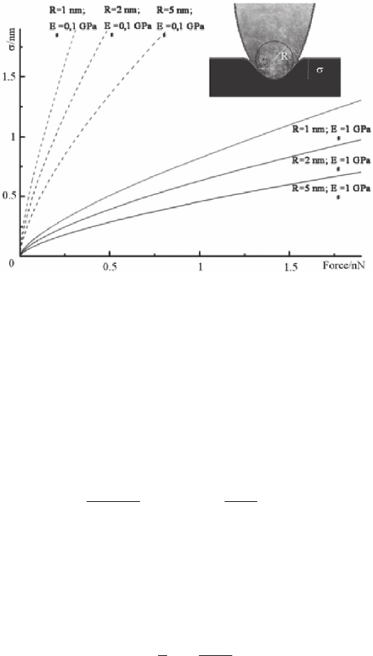
Figure 16–10. Parameter plot of the loading force F versus the penetration
depth σ for three different radii of curvature of the apex R and for two types
of differently stiff samples. A Young’s modulus of 0.1 GPa might refl ect a living
cell; 1 GPa could be ascribed to a protein structure. The plot shows that even
at a very low force, a sharp stylus dives right into the softer sample. It is there-
fore crucial to select the right kind of an apex radius for each application.
1036 M. Amrein
conformational change of the protein upon the higher load (Figure
16–11).
A convenient way to detect sample deformation upon too high a load
comes from comparison of images from trace and retrace (Hoh et al.,
1993; Müller et al., 1996; Schabert and Engel, 1994). Trace and retrace
refer to the line-by-line motion of the scanner. All commercial AFMs
allow two individual images to be acquired, one using the line traces
when the stylus moves from left to right and the other one using the
traces on the way back.
The actual load leading to high-resolution images might be even
smaller than expected from the force setting of the microscope. Yang
and co-workers (1996) proposed that short-range interactions with a
local asperity give rise to high-resolution contrast while longer-range
interactions with blunter parts of the tip help support the load of the
tip in contact with the sample. Muller et al. (1997) have argued that in
solution, the long-range force required for repulsion of the body of the
tip is electrostatic. They adjust the supporting electrolyte so that the
asperity just touches the sample lightly.
To obtain details of living cells and tissues by AFM, a meaningful
image is often obtained only after a loading force of a few nanonew-
tons has been applied. Such high loads lead to deformation of the cell
up to several hundred nanometers (Hoh and Schoenenberger, 1994).
The cell membrane is then pressed onto intracellular structures such
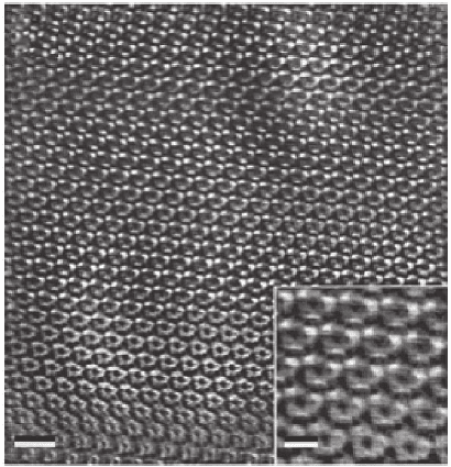
Figure 16–11. Force-dependent surface topography of bacteriorhodopsin
(scale bar represents 10 nm) demonstrating the effect of force variations on the
topography of the cytoplasmic purple membrane surface. The initial force of
300 pN (bottom of image) was decreased during the scan to 100 pN (top of
image). A conformational change is distinct: donut-shaped bacteriorhodopsin
trimers transform into units with three pronounced protrusions at their
periphery. Inset: noise reduced image at higher magnifi cation (scale bar rep-
resents 4 nm). (Courtesy of Müller and Büldt, 1995).

Chapter 16 Atomic Force Microscopy in the Life Sciences 1037
as the nucleus, cytoskeletal elements, and vesicles, which in conse-
quence become visible (Chang et al., 1993; Fritz et al., 1994; Hoh and
Schoenenberger, 1994). In these cases, the AFM images refl ect the local
plasticity of the living cells more than their true surface topography.
2.3.2 Forces between the Apex of the Stylus and the Sample
A van der Waals force F
vdW
is always present between the tip and
the sample. The main contribution to F
vdW
is the dispersion force,
caused by the dipole-induced dipole interaction and is present
between all kinds of materials. The Lifshitz theory, a combination of
quantum electrodynamics theory and spectroscopic data allows
the forces between two geometrically shaped surfaces to be calculated.
In the case of a fl at surface (representing the sample) and a sphere
(being used as an approximation for the apex of the stylus) F
vdW
is
(Israelachvili, 1991)
F
HR
d
vdW
a
=
−
6
2
where R is the radius of the tip (radius of the tip apex) and d is the
distance between apex and sample. H
a
represents the Hamaker con-
stant, which characterizes the interaction of the two surfaces (media)
across a third medium. For example, for two mica surfaces in water H
a
is 2.2 × 10
−20
J and for two silicon oxide surfaces in water H
a
is 8.3 × 10
−21
J
(Israelachvili, 1991). For hydrocarbons in water, H
a
lies between (0.2 − 1)
× 10
−20
J (Butt, 1992). The van der Waals force between particles is
always attractive in air and attractive for most situations in an aqueous
solution.
When imaging in aqueous solution, additional interactions between
the apex of the stylus and the sample need to be taken into account.
Many of the commonly used supports and probes as well as most bio-
logical samples are charged in an aqueous environment. This is because
they usually carry weak acidic and basic functional groups. They dis-
sociate in an aqueous solution, according to their equilibrium con-
stants. The net charge density of a surface in water depends on the
density of the functional groups, their pK values, and the pH of the
buffer solution.
The DLVO (Derjaguin, Landau, Verwey, Overbeek) theory quantita-
tively describes the total force between charged interfaces in aqueous
solution. It considers the electrostatic double-layer interaction caused
by surface charges and the van der Waals forces and neglects entropic
or steric contributions. Unlike the van der Waals interaction, the electri-
cal double-layer repulsion depends on the sign and magnitude of the
surface charge density, the ion concentration, and the pH. A charged
surface attracts counterions in the water. At the solid–liquid interface,
a charge cloud on the order of molecular dimensions is created as a
transition region. In this so-called electrical double layer (EDL) the
counterions balance the charge of the surface. The density of the
charges surrounding the surface falls off exponentially with distance
z from the surface (Debye–Hückel approximation):
ψ = ψ
0
e
−z/λ
D
1038 M. Amrein
ψ
0
represents the potential at the surface. The Debye length λ
D
is the
thickness of the EDL:
λ
εε
D
e
=
∑
0
22
kT
ecq
i
i
i
where ε
0
represents the vacuum permittivity, ε
e
the dielectric permit-
tivity of the electrolyte, k the Boltzmann constant, T the absolute tem-
perature, e the unit charge, and c
i
the concentration and q
i
the ionic
charge of the ith component of the liquid. Note the strong dependence
of the double layer thickness on the valence of the ions.
If the tip and the sample are approaching each other, the electrical
double layers of the two interfaces become perturbed when they begin
to overlap (Figure 16–12). This results in a force that is known as the
double layer force F
el
. F
el
decreases exponentially with distance d
between the two surfaces. For a stylus with an apex radius of curvature
of R and a planar sample (at a surface potential <50 mV) (Butt, 1992):
F
R
e
d
el
D
D
=
−
4
12
0
πσσλ
εε
λ
where σ
1
and σ
2
represent the surface charge density of the stylus and
the specimen, respectively, ε
0
is the vacuum permittivity, ε
e
the dielec-
tric permittivity of the electrolyte, and d the distance between the two
surfaces. This equation is a simplifi cation of any real situation. At a
distance much below λ
D
, it is necessary to resort to numerical solutions
for which there are no simple expressions.
In addition, when the two charged surfaces approach each other, the
local ion concentration also changes. This means a shift in the equilibrium
conditions of the charged groups with the ions in solution. Hence, the ion-
izable functional groups of the surface may become neutralized for fi nite
dissociation constants, according to the new equilibrium conditions, and
the surface charge density is decreased. This phenomenon is called charge
regulation and causes a less strong repulsive force for surfaces charged
with similar sign than would occur without charge regulation. F
el
can even
become attractive at very small distances (Israelachvili, 1991).
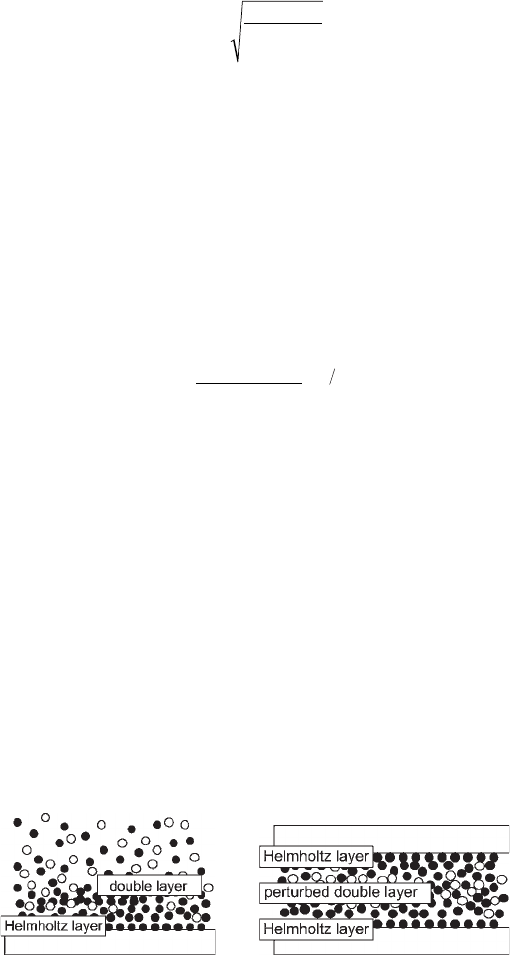
Figure 16–12. Specifi c interaction of ions at solid–liquid interfaces. The sur-
faces are negatively charged. (Left) The ions produce an interfacial region of
excess solute concentration, the electrical double layer, which consists of the
Debye layer and the counterions bound at the surface (Helmholtz layer).
(Right) Two negatively charged surfaces at very small separation. The ion
clouds of the electrical double layer overlap and cause a repulsive force
(Amrein and Müller, 1999). (From Mueller et al., 1997a, reprinted with
permission.)
Chapter 16 Atomic Force Microscopy in the Life Sciences 1039
To evaluate the overall force that is relevant for the interaction
between the stylus and the sample, the electrical double-layer force and
the van der Waals force are summed up to the total DLVO force (F
DLVO
)
(Figure 16–13).
F
R
e
HR
d
d
DLVO
Da
D
=+
−
−
4
6
12
0
2
πσσλ
εε
λ
For high-resolution imaging, the electrical double-layer repulsion
may have to be reduced such that the stylus can effectively come in
physical contact with the sample rather than “riding” on the electrical
double layer. This can be achieved by increasing the (bivalent) ion
concentration (Butt 1991, 1992; Butt et al., 1995; Ducker et al., 1991).
There are a number of interactions that need to be considered in
addition to the above-mentioned DLVO force, including steric, hydro-
phobic, and hydrophilic interactions.
When the microscopy is performed in air, there is often a water
bridge occurring between stylus and sample. This is because under
ambient conditions, most surfaces are covered by a thin water layer.
The resulting meniscus force may be quite strong (e.g., in the order of
10
−7
N) and may pull the tip effectively onto the sample. This will result
in poor resolution and may even cause damage to the sample and
stylus. It is notable that the van der Waals interaction in air is usually
about an order of magnitude stronger than in an aqueous environment.
The detrimental effects occurring in air through these forces may par-
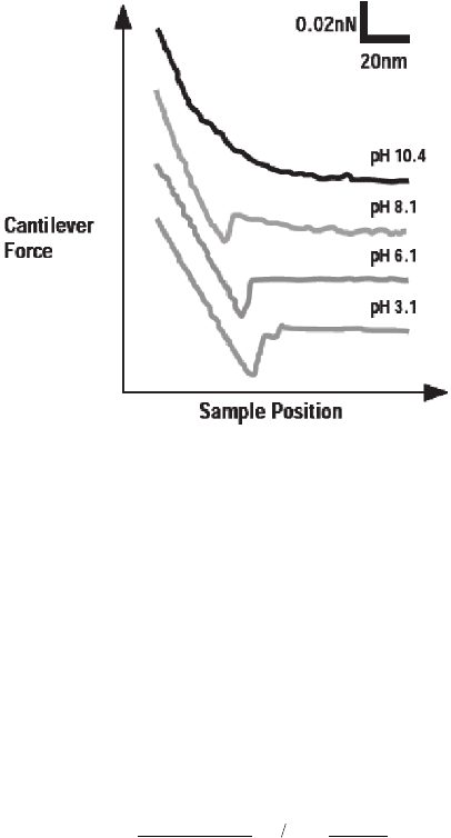
Figure 16–13. Force versus distance curves showing the DVLO force between
a silicon nitride cantilever and a mica surface under varying pH conditions
and at fi xed ion concentration. Mica is naturally negatively charged at neutral
pH, less charged at low pH, and increasingly charged at higher pH. At low
surface charge, the van der Waals attraction dominates and causes the tip to
snap onto the sample. At higher charge, the van der Waals attraction becomes
increasingly screened by the repulsive electrical double layer repulsion. (From
Butt, 1992, reprinted with permission).
