Gasch R., Twele J. (Eds.) Wind Power Plants: Fundamentals, Design, Construction and Operation
Подождите немного. Документ загружается.

432 13.1 Grid-connected wind turbines
m
4
s
m
6
s
m
8
s
m
12
s
m
v10
s
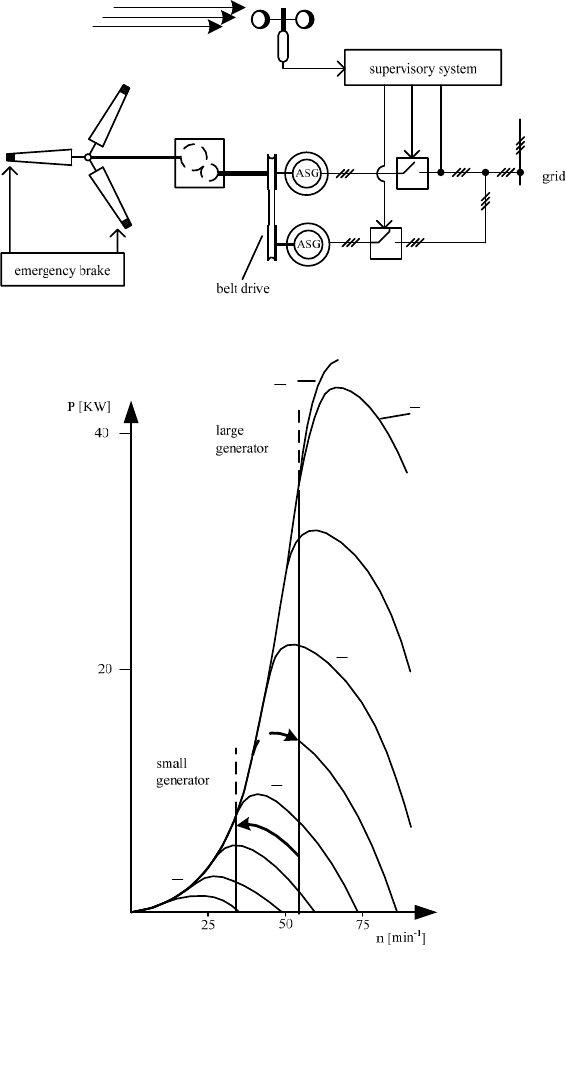
Fig. 13-2 Danish concept: Direct coupling of the asynchronous generator to the grid, nearly con-
stant speed (e.g. Vestas 15/55); tip spoiler as emergency brake min
-1
13 Concepts of electricity generation by wind turbines 433
For large wind turbines (P > 600 kW) many companies have abandoned the tip
spoiler in favour of pitching the entire blade. NEG Micon used tip spoilers, acti-
vated by centrifugal forces, up to a turbine size of D = 64 m, P = 1500 kW. Fig.
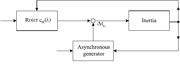
13-3 shows the simplified block diagram for wind turbines of the Danish concept
which operate entirely in the passive mode.
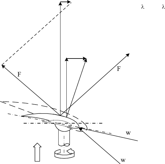
Fig. 13-4 shows the aerodynamic forces of lift and drag as well as the circum-
ferential force and the thrust in the section at half of the blade (r = 0,5 R, uniform
airfoil profile) of a small stall-controlled wind turbine designed for an optimum tip
speed ratio of 5.6. The vectors are shown for the design wind speed of 7.5 m/s and
for storm, i.e. a wind speed of 30 m/s.
From the direction of the relative velocities w
d
resp. w
s
relative to the profile
chord it is apparent that the angle of attack increases for storm so much that the
flow separates and the drag F
D.s
becomes correspondingly high. Thus, there is only
a moderate circumferential force F
tang.s
. The rotor “refuses” to exceed the maxi-
mum power P
max
of the generator.
The stall effect can be used to hold the power more or less constant during
strong winds (v
Wind
> v
rated
). The required blade design will then deviate slightly
from the ideal configuration of Betz-Schmitz. Usually, it suffices to mount the
ideal blade with a slightly “wrong” blade twist angle, differing by a few degrees,
to achieve a sufficiently constant power until cut-out.
The first generation of commercial stall-controlled wind turbines had power
ratings of less than 50 kW and a control system which was limited in its actions to
starting up, switching over between the generators and shutting down the wind
turbine as a function of the wind speed and power.
For larger wind turbines the control system has to operate more subtly since the
starting (short-circuit) current of an asynchronous motor-generator at the very first
moment before the squirrel-cage rotor starts to rotate reaches 6 to 8 times the rated
current, cf. section 11.2.1. Therefore, the machine is started in star connection be-
fore switching to delta connection which uses the full power. This reduces the cur-
rents in the wires significantly (by 1/1.73). If operation is always started with the
small generator, which has a rating of approx. 25% of the full rated power, the
start-up currents exceed the rated current of the big generator only slightly, for
which the electrical system was designed.
:
:
:
wind
v
grid
f
R
M
A
M
Fig. 13-3 Simplified block diagram of a wind turbine with an asynchronous generator at grid
connected operation (Danish concept)
434 13.1 Grid-connected wind turbines
thrust (T)
tangential force (tang)
drag (D)
lift (L)
W
V
:
tang.s
F
tang.d
F
T.d
F
L.d
F
T.s
F
d
s
velocities
L.s
stall (s)
design point (d)
D.s
d
= 5.6,
d.local
= 2.8
v
d
= 7.5 m/s
r = 1.05 m = 0.5 R
v
s
= 30 m/s
Profile FX 63-137
Re = 360000
Fig. 13-4 Forces at the blade section 0.5 R at the design point (index d) and with control by stall
effect during storm (index s)
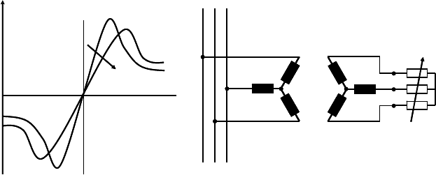
Stall-controlled wind turbines of more than 250 kW use more complex supervi-
sory and control systems. Not withstanding the passive limitations of power and
rotational speed by the stall-effect itself, more complicated control procedures are
required for switching under load.
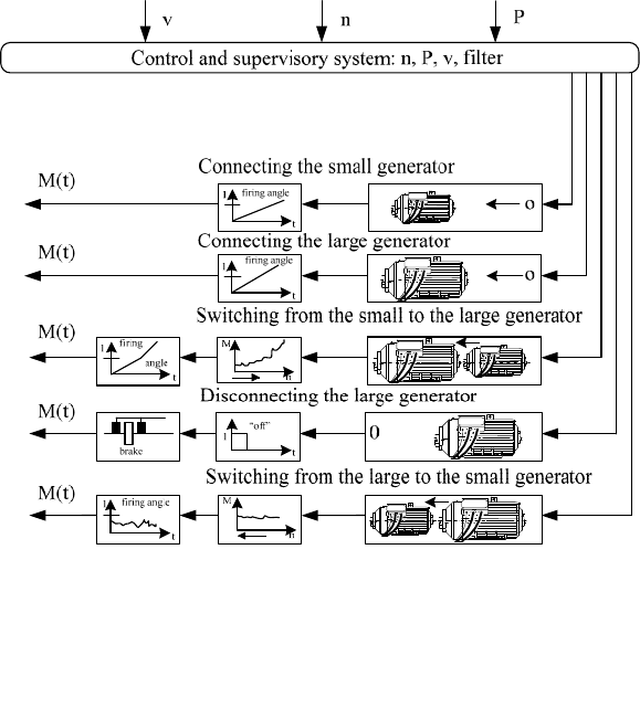
In particular, the smooth transition with a large power demands control of the
phase angle using thyristors. The transfer of power is built up gradually by
manipulation of the firing angle. That way, large in-rush currents are avoided. The
critical moments during switching over between the two generator speeds (see Fig.
13-2) can be controlled as well by operating the generator above its pull-out point
under a given constant load torque with a small firing angle of the thyristor. Fig.
13-5 shows the tasks of a typical control and supervisory system of a medium-
sized stall-controlled wind turbine (approx. 300 kW).
The turbines of Danish concept are very simple and robust, there are nonethe-
less three problems which led to further research and development.
To begin with, the grid operators dislike the reactive power consumption of the
asynchronous machine, sometimes a penalty has to be paid for it. Therefore, for
large stall-controlled wind turbines the reactive power compensation is done (in
13 Concepts of electricity generation by wind turbines 435
part) by capacitor banks. Certainly, it would be better to have controllable reactive
power as is the case for synchronous machines.
Secondly, there are high structural loads and power fluctuations because the
blades cannot be pitched in the strong wind range above the rated wind speed.
This was shown already in Fig. 6-17 for the thrust coefficient c
T
. Pitching the
blade by 20° towards feather reduces the idling tip speed ratio from 13.5 to 4.5,
and the corresponding thrust coefficient drops from 1.25 to approximately zero!
The third and most obvious disadvantage of stall-controlled wind turbines run-
ning at constant rotational speeds is shown in Fig. 13-2: the wind turbine works
with optimum aerodynamics only for two rotational speeds in the normal wind
range (at 5 and 8 m/s).
By contrast, an ideal variable-speed wind turbine would always run with the
design tip speed ratio thanks to a wind speed dependent control until the rated
generator power is reached, i.e. the rotational speed n has to be adapted to the
wind speed v(t).
Fig. 13-5 Control and supervisory system of a wind turbine with stall control (approx. 300 kW)
436 13.1 Grid-connected wind turbines
13.1.2 Directly grid-connected asynchronous generator with
dynamic slip control
The rigid coupling of the asynchronous generator (induction generator) to the grid
frequency causes high structural load during gusts and high winds, especially for
large asynchronous generators which operate with a very small slip s < 0.02 in or-
der to reduce power losses. If during gusts a larger slip is allowed briefly, the
structure is relieved and the power output is smoothened without permanent nega-
tive consequences for the efficiency.
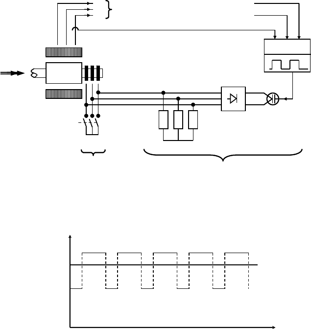
This concept can be performed using a slip-ring asynchronous generator. It has
a three-phase winding in the rotor, instead of the squirrel-cage, and, therefore, it is
possible to connect variable resistances into the rotor circuit. The increased resis-
tance in the rotor circuit leads to more slip, Fig. 13-6, as already discussed in
chapter 11, Fig. 11-25.
The block diagram of such a dynamic slip control is given in Fig. 13-7. For
normal winds the bridge at the slip rings is short-circuited mechanically. Thus, the
resistors are shorted out. There is normal generator operation with a moderate slip.
For strong winds the mechanical bridge is opened and the additional resistances in
the rotor circuit increase the slip, which can now be manipulated.
If the IGBT switch behind the rectifier is open the additional resistances are
fully added to the internal resistance of the windings in the rotor circuit, this pro-
duces a large slip. If the IGBT switch is closed the additional resistors are without
effect, as for the mechanically closed bridge.
The controller will use a clock in the kHz range to prescribe the fraction of time
for which the additional resistors are in the control circuits. Thus the mean resis-
tance R
m
can be adjusted to values between R
i
and R
i
+ R
add
, see Fig. 13-8.
:
sync
Motor Generator
Torque
R
Stator Rotor
R
:
sync
Motor Generator
Torque
R
Stator Rotor
R
Fig. 13-6 Influencing the generator characteristic by additional variable resistances in the rotor
circuit of an asynchronous machine
13 Concepts of electricity generation by wind turbines 437
If there is a steep increase in the torque resp. the current due to a wind gust the
controller will temporarily allow more slip. Afterwards it will return swiftly to the
more rigid coupling to the grid frequency (only R
i
).
This type of dynamic slip control has the disadvantage that during gusts power
has to be passed through the slip ring. However, it is advantageous that the resis-
tors which turn the power into heat may be located on top of the nacelle where the
heat dissipation is not an issue. Other types of dynamic slip control are described
in [5]. If now a blade pitching system is added to this type of control the work is
shared as follows:
- The short-term response to gusts is provided by the slip control.
- The adaption to changes in the mean wind speed is performed by the blade
pitching system (e.g. Vestas and other manufacturers).
Rotor
IGBT
switch
to grid
:
:
grid
I
Stator
:
L1
L2
L3
Controller
Rectifier
Additional resistances
Bridge
if P < P
rated
closed
„normal“
for strong winds: P | P
rated
bridge open
Rotor
IGBT
switch
to grid
:
:
grid
I
Stator
:
L1
L2
L3
Controller
Rectifier
Additional resistances
Bridge
if P < P
rated
closed
„normal“
for strong winds: P | P
rated
bridge open
Fig. 13-7 Block diagram of the dynamic slip control by additional variable resistances in the ro-
tor circuit of an asynchronous machine
t
Resistance
R
i
R
i
+R
add
R
m
t
Resistance
R
i
R
i
+R
add
R
m
Fig. 13-8 Slip manipulation through clocked switching of the additional resistance R
add
438 13.1 Grid-connected wind turbines
13.1.3 Variable-speed wind turbine with converter and direct
voltage intermediate circuit
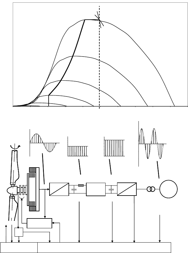
The schematic view of this wind turbine concept is given in Fig. 13-9. No gearbox
is required due to the direct-drive multi-pole synchronous generator of a large
diameter.
0,0
0,2
0,4
0,6
0,8
1,0
1,2
Rotational speed
P/P
2 m/s
4 m/s
6 m/s
8 m/s
10 m/s
12 m/s
14 m/s
16 m/s
max
n
max
n
min
.
.
.
.
.
.
.
0,0
0,2
0,4
0,6
0,8
1,0
1,2
Rotational speed
P/P
2 m/s
4 m/s
6 m/s
8 m/s
10 m/s
12 m/s
14 m/s
16 m/s
max
n
max
n
min
.
.
.
.
.
.
.
Grid informations
f
Grid
, voltage,
phases
Pitch control Electronical controller
Step-up
converter
Grid
///
Excitation
J
:
I
DC
U
DC
~
=
~
=
DC1
DC2
///
50 Hz
Transformer
J
u
DC1
(t)
u
DC2
(t)
u
Grid
(t)
u
Gen
(t)
Grid informations
f
Grid
, voltage,
phases
Pitch control Electronical controller
Step-up
converter
Grid
///
Excitation
J
:
I
DC
U
DC
~
=
~
=
DC1
DC2
///
50 Hz
Transformer
J
u
DC1
(t)
u
DC2
(t)
u
Grid
(t)
u
Gen
(t)
Fig. 13-9 Concept of a synchronous generator with AC-DC-AC converter
13 Concepts of electricity generation by wind turbines 439
At point DC1 of the converter the three-phase current of variable frequency has
been converted into direct current. For a low rotational speed the generator does
not reach the output voltage of 400 V despite full excitation. Therefore, the step-
up converter increases the voltage level (from DC1 to DC2 in Fig. 13-9). After
that the direct current of 400 V is turned into three-phase current of 50 (or 60) Hz
which is fed into the grid via the transformer.
Moreover, the DC intermediate circuit delivers information about the momen-
tary power (current I
DC
times voltage U
DC
) which, together with the rotational
speed, provides the control with the essentials of the operating state: the aim of the
generator control in the normal wind range is to follow the optimum trajectory of
“torque is proportional to :
2
“, cf. section 12.4.
The blade pitching system is inactive until the rated wind speed of 12 m/s is
exceeded. For stronger winds it limits the rotational speed with a certain flexibility
to the set value.
Since in the strong wind range the generator is operated with a (nearly) fixed
torque, cf. section 12.4, the power output is approximately constant.
The mechanical implementation of this wind turbine concept (E-40, E-66, etc.
by ENERCON) is impressively simple, cf. Fig. 3-30. The turbine is nearly “oil-
free” because there are electrical drives for the blade pitching system as well as for
the yaw system of the nacelle. The supply of reactive power can vary freely
between inductive and capacitive: there is no problem of reactive power consump-
tion as in the case of asynchronous machines.
Scaling the wind turbine up to rotor diameters of more than 100 m leads to an
impressive weight of the nacelle (approx. 500 t for the E-112). Wind turbines us-
ing a gearbox have a significantly smaller weight, cf. chapter 3.
13.1.4 Variable-speed wind turbine with doubly-feeding asynchro-
nous generator and converter in the rotor circuit
With dynamic slip control, section 13.1.2, the asynchronous machine is less rig-
idly coupled to the grid (s = 0.02 to 0.2). However, it requires the more complex
slip ring rotor instead of the squirrel-cage rotor. Since one percent slip equals one
percent power loss in the rotor, it is reasonable to allow high values of slip only
for brief intervals of time.
If the power, that was exported from the rotor, is not converted into heat, but is in-
stead fed into the grid via an AC-DC-AC converter the problem of heat dissipation
is avoided. And the efficiency of the generator is improved. However, the latter is
of little interest in the range of strong winds.
440 13.1 Grid-connected wind turbines
AS-rotor
Filter
~
=
DC
~
=
Transformer
P
Rotor
To the grid
///
P
Stator,
, f
Grid
f
Rotor
Stator
M
R
, n
///
AS-rotor
Filter
~
=
DC
~
=
Transformer
P
Rotor
To the grid
///
P
Stator,
, f
Grid
f
Rotor
Stator
M
R
, n
///
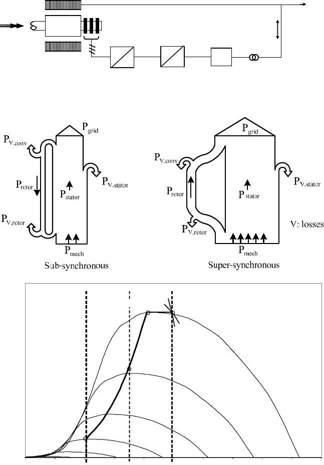
Fig. 13-10 Wind turbine with asynchronous generator and converter in the rotor circuit
0,0
0,2
0,4
0,6
0,8
1,0
1,2
Rotational speed
P/P
2 m/s
4 m/s
6 m/s
8 m/s
10 m/s
12 m/s
14 m/s
16 m/s
max
n
sync
sub- super-
synchronous
.
.
.
.
.
.
.
0,0
0,2
0,4
0,6
0,8
1,0
1,2
Rotational speed
P/P
2 m/s
4 m/s
6 m/s
8 m/s
10 m/s
12 m/s
14 m/s
16 m/s
max
n
sync
sub- super-
synchronous
.
.
.
.
.
.
.
.
.
.
.
.
.
.
Fig. 13-11 Operation of a doubly-feeding asynchronous generator with converter in the rotor
circuit below and above the synchronous speed (see Fig. 13-10),
Top: power flow; Bottom: relative power versus rotational speed
13 Concepts of electricity generation by wind turbines 441
This concept is performed using the so-called super-synchronous (i.e. above-
synchronous) converter cascade [1].
If the range of operation of the asynchronous generator below the synchronous
speed is to be improved as well, a part of the stator power will have to be fed into
the rotor with suitable values of frequency and voltage. This requires a certain
control effort from the power electronics [2, 3, 5]. Fig. 13-11 shows the power
flow in stator and rotor for operation below and above synchronous speed of the
machine.
In this configuration, the asynchronous generator can have a speed range as
large as that of the synchronous machine with a (full power) converter. However,
the converter in the rotor circuit has to cover only approx. 20% of the rated power.
Therefore, it is less expensive and also has smaller losses. The more complex con-
trol in the rotor circuit can also decide whether the asynchronous machine should
consume or supply reactive power in order to meet the present needs of the grid.
13.1.5 Power curves and power coefficients of three wind turbine
concepts– a small comparison
The Figs. 13-12 and 13-13 show for comparison the power curves P(v) and the to-
tal power coefficients c
P.tot
(v) of three different wind turbine types. The total
power coefficient includes rotor, gearbox, generator and converter efficiencies.
The data were taken from type approval measurements, reported in market surveys
[11, 15]. The power curves differ noticeably because the wind turbines have dif-
ferent rotor diameters:
- NORDEX N43, D = 43 m, P = 600 kW:
- Classical Danish concept with two fixed rotor speeds;
- asynchronous machine and stall control (section 13.1.1)
- ENERCON E-40/6.44, D = 44 m, P = 600 kW:
- Variable-speed synchronous machine with AC-DC-AC (full power)
- converter and pitch control (section 13.1.3)
- SÜDWIND S.46, D = 46 m, P = 750 kW:
- Variable-speed doubly-fed asynchronous machine with AC-DC-AC con-
verter in the rotor circuit and pitch control (section 13.1.4)
From the power curves it is only apparent that the wind turbines with larger
diameter deliver more power, except for the cut-in range where the curves inter-
sect at 5.5 m/s.
