Gasch R., Twele J. (Eds.) Wind Power Plants: Fundamentals, Design, Construction and Operation
Подождите немного. Документ загружается.

402 12.1 Methods to manipulate the drive drain
Within the individual fields of operation, e.g. zone 1, normal wind (4 to 12 m/s),
the control and the controller loops work autonomously. Nevertheless, the current
status has to be reported continuously to the supervisory system, since only this
system can decide if the set control values are still valid or whether it is necessary
to shift to a different mode of operation by a maneuver. A considerably simplified
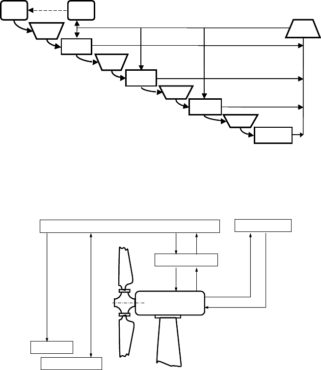
flow chart of the supervisory system is shown in Fig. 12-3.
In the hierarchy of systems, given in Fig. 12-4, the supervisory system is above
the control systems.
Start
Maschine
O.K.?
Stillstand
Gehe zu
Gehe zu
Start
in den
Betrieb I
Teillast
Betrieb II
Vollast
Trudel-
betrieb
Gehe
zurück zu
StopStart
Machine
O.K.?
Stand still
Go to
Go to
Start
Operation I
Part. load
Operation
II
Full load
Idling
Go
back to
StopStart
Maschine
O.K.?
Stillstand
Gehe zu
Gehe zu
Start
in den
Betrieb I
Teillast
Betrieb II
Vollast
Trudel-
betrieb
Gehe
zurück zu
StopStart
Machine
O.K.?
Stand still
Go to
Go to
Start
Operation I
Part. load
Operation
II
Full load
Idling
Go
back to
Stop
Fig. 12-3 Simplified flow chart of the supervisory system, variable-speed wind turbine
Monitoring
Supervisory System
Control Systems
Safety System
Remote Control
Monitoring
Supervisory System
Control Systems
Safety System
Remote Control
Fig. 12-4 Hierarchy of the systems
12 Supervisory and control systems for wind turbines 403
Phases
Supervisory system
Pitch control Yaw control Generator
excitation
Converter control
J ȕ
:
:
U
gen
U
DC
I
DC
v
wind
Anemometer
Speed Pitch
angle
Yaw
angle
External
information
u
grid
f
grid
J
Wind
Generator
=
~
=
~
:,M
T
DC
DC
I
U
AC
AC
Converter
Transformer
Direction
Phases
Supervisory system
Pitch control Yaw control Generator
excitation
Converter control
J ȕ
:
:
U
gen
U
DC
I
DC
v
wind
Anemometer
Speed Pitch
angle
Yaw
angle
External
information
u
grid
f
grid
J
Wind
Generator
=
~
=
~
:,M
T
DC
DC
I
U
AC
AC
Converter
Transformer
Phases
Supervisory system
Pitch control Yaw control Generator
excitation
Converter control
J ȕ
:
:
U
gen
U
DC
I
DC
v
wind
Anemometer
Speed Pitch
angle
Yaw
angle
External
information
u
grid
f
grid
J
Wind
Generator
=
~
=
~
:,M
T
DC
DC
I
U
AC
AC
Converter
Transformer
Direction
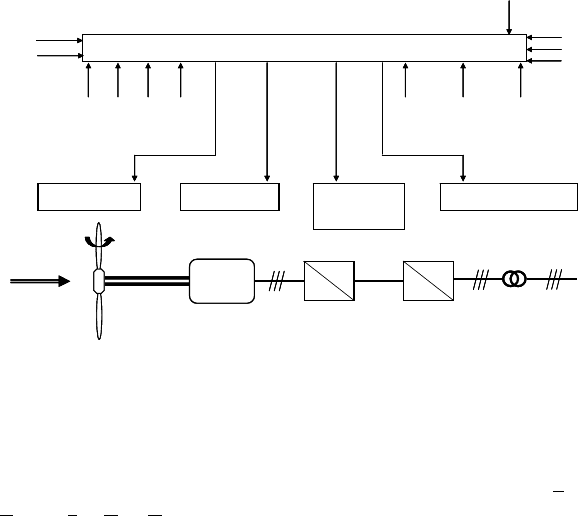
Fig. 12-5 Supervisory system - controllers - scheme of drive train with converter
Fig. 12-5 shows the most important controllers of a variable-speed wind turbine
and the necessary sensor information.
The supervisory system governs also the SCADA system (SCADA = Supervi-
sory Control and Data Acquisition) which consists of the monitoring and remote
control modules. The monitoring module collects operational data (e.g. perform-
ance data and faults, etc.) and delivers required information “outwards”, e.g. to the
wind farm management office. The data transfer is either continuous or upon
demand, e.g. via modem. The monitoring module cannot intervene in the turbine
operation, therefore “it has no responsibility”. The remote control serves e.g. to
turn the wind turbine on and off from the wind farm management office or to reset
the control after having checked and cleared a minor fault. For some machines,
even control parameters or operating modes (e.g. noise reduced operation) can be
set via the remote control.
The safety system has the responsibility for safe operation. It acts at once and
directly if severe malfunctions occur, e.g.
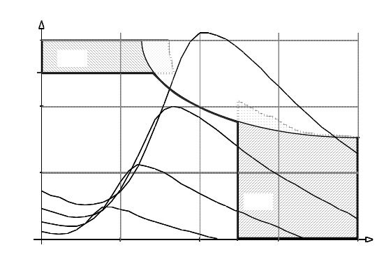
- Excessive rotational speed (overspeed), Fig. 12-6 or
- Excessive power or torque,
- Differences among the pitch angles of the blades
- Excessive vibrations (unbalance, icing on the blades)
- Manual emergency shut-down, etc.
The safety system must assure that the wind turbine at no time damages or de-
stroys itself. If a malfunction occurs it has to shut down the wind turbine fast and
reliably and disengage it.
Therefore, this system has to be simple and robust (preferably hardware-based),
and redundant in the most important components (e.g. two independent braking
systems) and be of fail-safe design. In case of failures in the electronics or hydraulics
404 12.1 Methods to manipulate the drive drain
the system has to bring the turbine into a safe state automatically and without use
of external energy (e.g. braking to standstill). This has to be assured anytime, dur-
ing any operating state or maneuver.
n
[Nm]
100 200 300 4000
50
100
1
50
4 m/s
6 m/s
10 m/s
8 m/s
P
max
M
max
n
max
Speed n in rpm
Torque M in Nm
n
[Nm]
100 200 300 4000
50
100
1
50
4 m/s
6 m/s
10 m/s
8 m/s
P
max
M
max
n
max
Speed n in rpm
Torque M in Nm
Fig. 12-6 Operating range limits for rotational speed, torque and power of a small wind turbine
D = 4 m (see Figs. 6-8 and 6-9)
12.1 Methods to manipulate the drive drain
Basically, the drive train can be influenced either through aerodynamics at the ro-
tor side, or by load manipulation, i.e. at the generator side (mechanical load side).
The wind turbine produces torque and thrust depending on the wind speed and
the angle of attack of the blade sections, cf. chapters 5 and 6. The angle of attack
itself depends on the rotational speed, the pitch angle and also on the yaw angle
between rotor axis and wind. The driving torque feeds the mechanical load. If the
driving torque is larger than the load torque the positive torque difference acceler-
ates the drive train, Fig. 12-7.
For a quantitative consideration of the control processes the inertia of the drive
train (and rotor) has to be considered, for larger wind turbines also the torsional-
vibrations behavior. The build-up of aerodynamic forces at the blades (Wagner-
Küssner’ functions) is usually so rapid, that the blade performance characteristics,
which were derived with the assumption of stationary behavior, can be used - see
annex II of this chapter.

12 Supervisory and control systems for wind turbines 405
Turbine
M = M (, v, )
( ) )
Driving
torque M
Blade pitch J
-M
L
+
Wind
v
(t)
T = T
Load torque
-
M
Thrust T
ǻM
Angular
speed
ȍ
Inertia Ĭ
Wind turbine with…
low tip speed ratio | high tip speed ratio
v
Yaw angle ȕ
Rotor-Wind
ȍ
, v,
ȍ
)
³
4
'
': dt
M
Turbine
M = M (, v, )
( ) )
Driving
torque M
Blade pitch J
-M
L
+
Wind
v
(t)
T = T
Load torque
-
M
Thrust T
ǻM
Angular
speed
ȍ
Inertia Ĭ
Wind turbine with…
low tip speed ratio | high tip speed ratio
v
Yaw angle ȕ
Rotor-Wind
ȍ
, v,
ȍ
)
³
4
'
': dt
M
Fig. 12-7. Controlling the drive train of a wind turbine via aerodynamics and electrical load
12.1.1 Aerodynamic manipulation measures
The following are simple methods to reduce the power extraction of the rotor dur-
ing strong winds:
- Turning the rotor out of the wind (Western mill),
- Holding the rotational speed constant in order to provoke flow separation
at the blades during strong winds,
- Deploying spoilers or brake flaps.
A more elegant method is the pitching of the blades which will be discussed later.
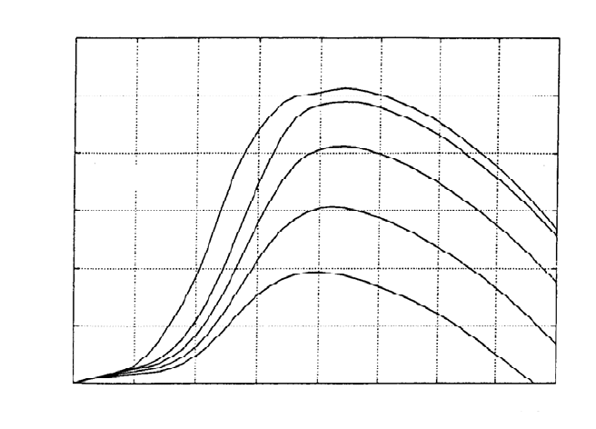
Fig. 12-8 shows the effects of turning the rotor out of the wind (i.e. producing
oblique flow) on the power characteristics of a small wind turbine with a high de-
sign tip speed ratio for strong winds. This is similar to the principle of the Western
mill. With increasingly oblique flow, the maximum of the power curve decreases,
but the corresponding rotational speed remains nearly constant.
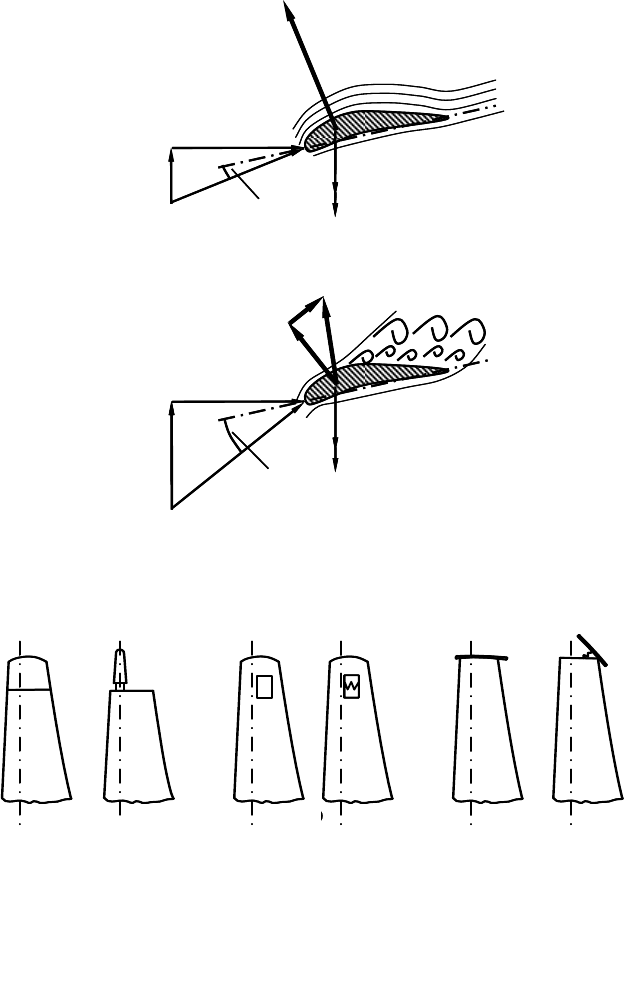
If the rotational speed is kept constant for strong winds, the circumferential com-
ponent in the velocity triangles does not change, Fig. 12-9. This can be used to
limit aerodynamically the power extraction of the wind turbine, as already discov-
ered in the 1950s by Johannes Juul, the ingenious inventor of the “Danish con-
cept”. The angle of attack
D
A
increases with stronger winds so much that the flow
separates (stall effect). Thus, the drag grows strongly and rotates the resulting
force R to point more downwind, Fig. 12-9. With a sophisticated blade design it is
possible to keep its circumferential component in the strong wind zone nearly con-
stant – and therefore the power as well since the rotational speed is already fixed.
The “Danish concept” was turned into practice by Juul using an induction (i.e.
asynchronous) generator which has its rotational speed more or less rigidly tied to
the three-phase grid frequency (50 or 60 Hz). This turns out to be a load control
utilizing cleverly the effect of flow separation.
406 12.1 Methods to manipulate the drive drain
n in rpm
0 50 100 150 200 250 300 350 400
6
5
4
3
2
1
0
P in kW
0°
20°
30°
50°
40°
v = 10 m/s
n in rpm
0 50 100 150 200 250 300 350 400
6
5
4
3
2
1
0
P in kW
0°
20°
30°
50°
40°
v = 10 m/s
n in rpm
0 50 100 150 200 250 300 350 400
6
5
4
3
2
1
0
P in kW
0°
20°
30°
50°
40°
v = 10 m/s
Fig. 12-8 Effect of turning the rotor out of the wind on the power characteristics of a turbine
with a high tip speed ratio (angle between rotor and wind, see fig. 12-19 and 12-1)
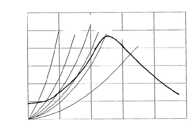
Flaps and spoilers are aerodynamic brakes which protect against overspeed or
serve as a simple means to limit and control power. They are activated by aero-
dynamic or centrifugal forces or are forced by a hydraulic control.
The braking torque M
fl
from a flap areas A
fl
can be easily estimated given the
assumption that they are located at the outer radius R, and using the simplification
that relative velocity equals circumferential speed
:
R. The braking torque M
fl
of
the flaps is then obtained by equating it to the driving torque M
R
of the rotor,
M
R
= M
fl
, since our goal is to assure that the rotor does not speed up to load-free
idling
c
M
(Ȝ) A
R
v
2
R ȡ/2 = c
D.fl
A
fl
(:
R)
2
R
U
/2 , (12.1)
where A
R
is the rotor swept area resp. A
fl
the flap area. The drag coefficient c
D.fl
is mostly equal to that of a rectangular plate and is in the range between 1.2 to 2.0
depending on the aspect ratio. c
M
(Ȝ) is the torque moment coefficient of the rotor.
Equation (12.1) may be transformed into the dimensionless equation
c
M
(Ȝ) = c
M.fl
(Ȝ) . (12.2)
12 Supervisory and control systems for wind turbines 407
D
A.stall
u = const
v
2.stall
c
u = const
v
2.opt
c
:
D
A.opt
:
R
L
D
Normal wind
Strong wind
L
R
|
D
A.stall
u = const
v
2.stall
c
u = const
v
2.opt
c
:
D
A.opt
:
R
L
D
Normal wind
Strong wind
L
R
|
Fig. 12-9 Triangles of velocity at design point and under strong wind conditions: flow separa-
tion (stall effect) due to constant rotational speed and resulting reduction of lift and increase of
drag
a) b) c)a) b) c)
Fig. 12-10 Different types of braking flaps a) turnable blade tip, b) braking flap in the blade sur-
face, c) fold-out end disk
The flap torque moment coefficient c
M.fl
(Ȝ) is
c
M.fl
= c
D.fl
O
2
A
fl
/ A
R
Ł f · O
2
. (12.3)
The factor f is determined by the ratio of flap area to rotor area.
408 12.1 Methods to manipulate the drive drain
0 2 4 6 8 Ȝ 10
0.12
0.1
0.08
0.06
0.04
0.02
0
0
c
kl
, c
M
c
M
1/500
1/250
1/200
1/150
1/100
f = 1/50
0 2 4 6 8 Ȝ 10
0.12
0.1
0.08
0.06
0.04
0.02
0
0
c
kl
, c
M
c
M
1/500
1/250
1/200
1/150
1/100
f = 1/50
Fig. 12-11 Operating points on c
M
(
O
-curve of the rotor depending on the flap size;
parameter f = c
D.flap
· A
flap
/A
rotor
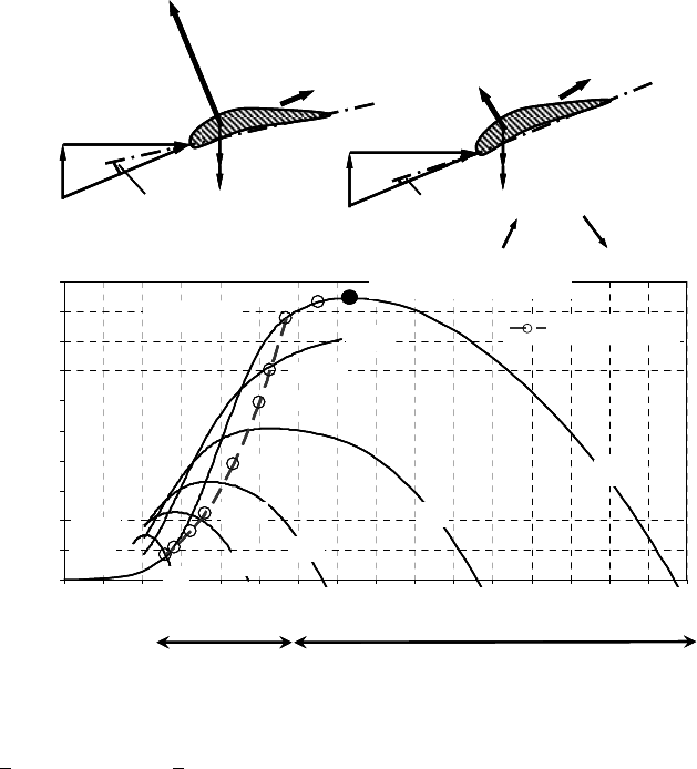
After plotting the curve c
M.fl
(
O
) =
O
2
f into the c
M
-O diagram, Fig. 12-11, the in-
tersection of this curve and c
M
(
O
) gives the operating point of the system ‘wind
turbine with deployed flaps. Turbines with a high tip speed ratio require only
small flap areas: for a wind turbine with a design tip speed ratio of
O
D
= 7, the
idling tip speed ratio would be reduced from
O
idle
= 13 to approximately 6.5, pro-
vided that the area of the deployed flaps is 1/500 of the rotor area. In contrast to
that, turbines with a low tip speed ratio require very large flap areas: a spoiler
brake is not suitable for this.
The most elegant and accurate method of aerodynamically influencing the rotor
is provided by a blade pitching system. There are two alternatives to be distin-
guished:
- Reducing the angle of attack
D
A
(pitching to feather, i.e. nose into
the wind, resp. trailing edge out of the wind) by increasing the blade
pitch angle
J
, Fig. 12-12, and
- Increasing the angle of attack
D
A
(pitch to stall, i.e. nose out of the
wind, resp. trailing edge into the wind) by reducing the blade pitch
angle
J
, Figs. 12-13.
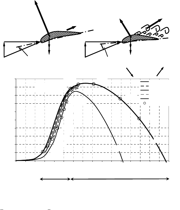
If at constant wind speed, Fig. 12-12 top, the pitch angle is increased, the angle of
attack at a blade section is reduced from the point of optimum flow conditions to
smaller angles of attack. Therefore, the lift is reduced - and consequently the
power output since the driving circumferential component of the lift, which wants
to accelerate the rotor, gets smaller. In Fig. 12-12, bottom, the influence of the
blade pitch angle on the power coefficient curve c
P
(
O
) is shown. The rotor char-
12 Supervisory and control systems for wind turbines 409
acteristics of a wind turbine with a high design tip speed ratio for various pitch
angles are given in the Figs. 6-15 to 6-17.
Pitch control systems which operate with a reduction of the angle of attack
(pitch to feather) to smaller values have a good accuracy and produce a smoothly
running rotor since for all occurring angles the flow remains attached to the blade.
The disadvantage is that in the range od strong winds the pitch angle will require
relatively large changes, see Fig. 12-14.
u = ˖r
v
2
c
D
A.D
:
dL
dD
u = ˖r
v
2
c
D
A
< D
A.D
:
dL
dD
Pitch to feather:
J => D
A
Normal operation, zone 1
0
0,05
0,1
0,15
0,2
0,25
0,3
0,35
0,4
0,45
0,5
012345678910111213141516
Tip speed ratio
OO
Power coefficient c
P
Operating points
Zone 2
Zone 1
Ȗ
= 5
o
Ȗ
= 0
o
10
o
15
o
25
o
20
o
10 m/s
4- 9 m/s (
Ȝ
=
Ȝ
opt
)
25 m/s
V
R
= 11,4 m/s
13 m/s
12,3 m/s
18 m/s
23 m/s
20 m/s
15 m/s
.
.
.
.
.
.
.
.
.
.
.
.
u = ˖r
v
2
c
D
A.D
:
dL
dD
u = ˖r
v
2
c
D
A
< D
A.D
:
dL
dD
Pitch to feather:
J => D
A
Normal operation, zone 1
0
0,05
0,1
0,15
0,2
0,25
0,3
0,35
0,4
0,45
0,5
012345678910111213141516
Tip speed ratio
O
O
Power coefficient c
P
Operating points
Zone 2
Zone 1
Ȗ
= 5
o
Ȗ
= 0
o
10
o
15
o
25
o
20
o
10 m/s
4- 9 m/s (
Ȝ
=
Ȝ
opt
)
25 m/s
V
R
= 11,4 m/s
13 m/s
12,3 m/s
18 m/s
23 m/s
20 m/s
15 m/s
u = ˖r
v
2
c
D
A.D
:
dL
dD
u = ˖r
v
2
c
D
A
< D
A.D
:
dL
dD
Pitch to feather:
J => D
A
Normal operation, zone 1
0
0,05
0,1
0,15
0,2
0,25
0,3
0,35
0,4
0,45
0,5
012345678910111213141516
Tip speed ratio
O
O
Power coefficient c
P
Operating points
Zone 2
Zone 1
Ȗ
= 5
o
Ȗ
= 0
o
10
o
15
o
25
o
20
o
10 m/s
4- 9 m/s (
Ȝ
=
Ȝ
opt
)
25 m/s
V
R
= 11,4 m/s
13 m/s
12,3 m/s
18 m/s
23 m/s
20 m/s
15 m/s
.
.
.
.
.
.
.
.
.
.
.
.
Fig. 12-12 Control by pitching to feather, top: reduction of angle of attack D
A
by increasing the
pitch angle
J
; bottom: corresponding power characteristic c
P
(
O
) for blade angle
J
= 0° in zone 1
(v <
11,4 m/s) and 0° <
J
< 25° for zone 2 (11,4 m/s < v < 25 m/s), see fig. 12-2
410 12.1 Methods to manipulate the drive drain
u
v
2
c
D
A.D
:
dL
dD
u
v
2
c
D
A
> D
A.D
:
dL
Pitch to stall:
dD
dL < dL
D
dD>dD
D
J => D
A
0
0,05
0,1
0,15
0,2
0,25
0,3
0,35
0,4
0,45
0,5
012345678910111213141516
Schnelllaufzahl [-]
aerodyn. Leistungsbeiwert Cp [-]
0
- 1
- 2
- 3
- 4
Betriebspunkte
10 m/s
5 m/s
8 m/s
6 m/s
13,7 m/s
v
nenn
= 11,4 m/s
13 m/s
12,3 m/s
18 m/s
23 m/s
20 m/s
15 m/s
Ȗ
= 0
o
Ȗ
= - 4
o
Zone 2 Zone 1
o
o
o
o
o
Operating points
Tip speed ratio
v
R
=
Power coefficient c
P
Normal operation, zone 1
.
.
.
.
.
.
.
.
.
.
u
v
2
c
D
A.D
:
dL
dD
u
v
2
c
D
A
> D
A.D
:
dL
Pitch to stall:
dD
dL < dL
D
dD>dD
D
J => D
A
0
0,05
0,1
0,15
0,2
0,25
0,3
0,35
0,4
0,45
0,5
012345678910111213141516
Schnelllaufzahl [-]
aerodyn. Leistungsbeiwert Cp [-]
0
- 1
- 2
- 3
- 4
Betriebspunkte
10 m/s
5 m/s
8 m/s
6 m/s
13,7 m/s
v
nenn
= 11,4 m/s
13 m/s
12,3 m/s
18 m/s
23 m/s
20 m/s
15 m/s
Ȗ
= 0
o
Ȗ
= - 4
o
Zone 2 Zone 1
o
o
o
o
o
Operating points
Tip speed ratio
v
R
=
Power coefficient c
P
Normal operation, zone 1
u
v
2
c
D
A.D
:
dL
dD
u
v
2
c
D
A
> D
A.D
:
dL
Pitch to stall:
dD
dL < dL
D
dD>dD
D
J => D
A
0
0,05
0,1
0,15
0,2
0,25
0,3
0,35
0,4
0,45
0,5
012345678910111213141516
Schnelllaufzahl [-]
aerodyn. Leistungsbeiwert Cp [-]
0
- 1
- 2
- 3
- 4
Betriebspunkte
10 m/s
5 m/s
8 m/s
6 m/s
13,7 m/s
v
nenn
= 11,4 m/s
13 m/s
12,3 m/s
18 m/s
23 m/s
20 m/s
15 m/s
Ȗ
= 0
o
Ȗ
= - 4
o
Zone 2 Zone 1
o
o
o
o
o
Operating points
Tip speed ratio
v
R
=
Power coefficient c
P
Normal operation, zone 1
.
.
.
.
.
.
.
.
.
.
Fig. 12-13 Active-stall control, top: increase of angle of attack
D
A
(stall effect) by reducing the
pitch angle
J
; bottom: corresponding power characteristic c
P
(
O
) for blade angle
J
= 0° in zone 1
(v <
11,4 m/s) and -4° <
J
< 0° for zone 2 (11,4 m/s < v < 25 m/s)
Increasing the angle of attack (active stall, nose out of the wind) leads to a reduc-
tion of the power output as well, since the flow will separate from the blade,
which reduces the lift (a little) and increases the drag significantly, Fig. 12-13.
Provoking flow separation requires only small pitch angle changes and even
achieving a controlled rotor standstill is easy. But the thrust remains quite large for
this type of pitch control.
Fig. 12-14 compares the required pitch angle for constant power control in the
range of strong winds (11.4 to 25 m/s). Obviously, the stall-controlled wind tur-
bine requires only very small changes of the pitch angle to keep the power output,
which was originally slightly rippled, really constant.
The summary of the different ways to influence the rotor by blade pitching in
Table 12.1 gives an overview of the possibilities for wind turbine rotor operation.
Practical examples exist for each field in this table.
12 Supervisory and control systems for wind turbines 411
-5
0
5
10
15
20
25
4 6 8 1012141618202224
Windgeschwindigkeit [m/s]
Blattwinkel [°]
Pitchen in Fahnenstellung
Pitchen in den Abriss (Active-Stall)
Wind speed
Pitch angle [rr]
Pitch to feather
Pitch to stall (Active stall)
A
c
t
i
ve
s
t
a
l
l
P
i
t
c
h
t
o
f
e
a
t
h
e
r
-5
0
5
10
15
20
25
4 6 8 1012141618202224
Windgeschwindigkeit [m/s]
Blattwinkel [°]
Pitchen in Fahnenstellung
Pitchen in den Abriss (Active-Stall)
Wind speed
Pitch angle [rr]
Pitch to feather
Pitch to stall (Active stall)
A
c
t
i
ve
s
t
a
l
l
P
i
t
c
h
t
o
f
e
a
t
h
e
r
Fig. 12-14 Blade angle pitching to feather or to active stall in order to limit the power to rated
power P
R
for strong winds (v > v
R
= 11.4 m/s )
Table 12.1 Overview of possibilities for wind turbine rotor operation
Blade angle pitching
none To feather To stall
constant
e.g. wind turbines
of the classical
“Danish concept “
e.g. early MW wind
turbines
„active stall“
wind turbines
Rotor speed
variable
e.g. battery chargers
modern variable-
speed wind turbines
with A.C.-D.C.-A.C.
converter
At present not a
common wind
turbine concept
12.1.2 Drive train manipulation using the load
In chapter 10 on wind pump systems we already discussed how the differences in
the speed-torque characteristics of piston pumps and centrifugal pumps influence
the behavior of the total system. Moreover, from chapter 11 we know several
methods of drive train manipulation through the generator. They are briefly sum-
marized here:
