Gasch R., Twele J. (Eds.) Wind Power Plants: Fundamentals, Design, Construction and Operation
Подождите немного. Документ загружается.

392 11.2 Three-phase machines
11
f,U
11
f,U
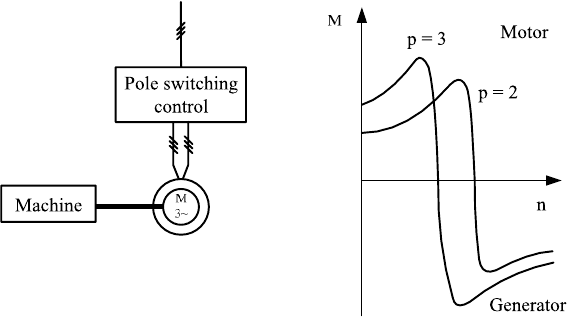
Fig. 11-26 Pole switchable induction machine, torque versus speed
If additional resistance is introduced to the rotor circuit via slip rings which
increases R´
2
, the characteristic becomes more flat. Consequently a change of the
load produces a larger change of the speed, i.e. the slip increases.
This effect is used for the dynamic slip control, see Fig. 13-7 in section 13.11.2.
A short-term increase of the rotor speed (and the slip) are allowed by increased
R´
2
, so that during strong wind gusts energy can be stored as kinetic energy in the
rotor. This relieves the structure, but causes (short-term) higher losses. If the grid
voltage U
G
increases, the magnitude of the pull-out torque is changed, but not its
position on the speed axis.
The possibility to change the synchronous speed of the induction machine by
switching the number of pole pairs was already mentioned. Fig. 11-26 shows the
practical consequences.
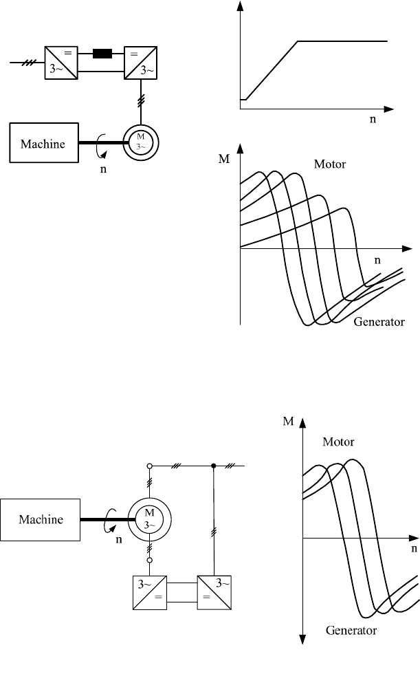
The speed of the induction (asynchronous) machine can be manipulated in a sig-
nificantly larger range if the rotor frequency can be set independent of the grid
frequency. Today, this is achieved using converters. The grid voltage is rectified
and fed into an intermediate DC circuit. This intermediate circuit then feeds a
three-phase inverter which makes it possible to supply a wide range of frequencies
and voltages. If this is used to feed the stator of a machine with a squirrel-cage
rotor, its speed will be variable over a wide range, Fig. 11-27.
In slip-ring rotor machines, the rotor can be fed so that the speed can be varied
by manipulating the rotating field of the rotor [6], Fig. 11-28. This type of
machine is called doubly-fed induction machine with variable-speed operation
this is used in many wind turbines of the MW class, section 13.1.4. We will deal with
this machine and the converter technology in the next section.
11 Wind turbines for electricity generation - basics
393
2
U
1, 1
fU
2
2
f
U
Fig. 11-27 Speed control of a squirrel-cage rotor induction machine by a frequency converter in
the stator circuit; block diagram, voltage and torque
11
f,U
22
f,U
0U
2
Fig. 11-28 Speed control of a slip ring rotor induction machine by a frequency converter in the
rotor circuit, block diagram, torque
394 11.3 Power electronic components of wind turbines - converters
11.3 Power electronic components of wind turbines - converters
Power electronics liberates the electricity generating wind turbines from the rigid
(synchronous generator) or nearly rigid (induction generator) coupling to the grid
frequency of 50 (or 60) Hz. Rectifier, inverter and converter (AC-DC-AC con-
verter) are simple “current valves” with the characteristics described below.
The diode is the simplest semi-conductor element. Only the positive half-wave
of an alternating voltage is allowed to pass current through. Current flow is possi-
ble only in one direction, table 11.1. for negative voltage the diode blocks the flow
of current. The diode is a passive circuit element and has no control input.
The thyristor has similar properties, but the start of the conduction in the posi-
tive half-wave can be triggered by a firing pulse. Once switched on, the thyristor is
reset only by the next zero crossing of the voltage. This limitation no longer exists
for the gate turn-off thyristor (GTO) which can be switched on and off within the
positive half wave, clocked with up to several hundred Hertz.
Power transistors allow even more manipulation. They are flow-control valves
which can be opened and closed nearly arbitrarily in the conducting range.
The
triggering frequencies reach up to several kilohertz (IGBT). It is possible to con-
vert alternating voltage into direct voltage and to generate from this another alter-
nating voltage of nearly any frequency. The same applies to the currents.
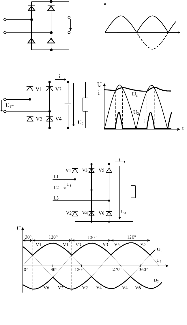
In order to use both half waves of an AC source, diodes can be connected to
form a rectifier bridge, see Fig. 11-29. the bridge contains two diodes in series on
each side and has the AC source feeding into the diagonal branch. Fig. 11-31
shows the extension of this configuration to three-phase inputs.
Rectifiers feed from an alternating or three-phase circuit of any frequency into
a DC circuit. The most simple imaginable rectifier consists of four diodes to feed
into a direct current circuit (bridge rectifier, Fig. 11-29). At any time the current
flows through one diode of the upper and lower bridge section. For the positive
half-wave these are the valves V1 and V4, for the negative half-wave V2 and V3.
Therefore, each diode passes current for 180°. The changing of the conduction
from one section to another is called commutation. The voltage is now rectified,
but it is still quite rippled that for most applications it has to be smoothened by a
capacitor. In that case the current flow time in the diodes is reduced, Fig. 11-30.
The larger the capacitor and the smaller the load the smaller the ripple.
If the bridge rectifier is extended by another section the three-phase bridge is
obtained in B6U connection, Fig. 11-31. The ripple of the voltage is even smaller
with this circuit, compared to the simple bridge rectifier. The current flows as well
through one diode of the upper and lower bridge section at a time, but now only
for 120°.
Using controllable valves, the magnitude of the voltage in the intermediate circuit
can be influenced actively through the delay angle. For a half-controlled bridge
type B6H , e.g. the diodes V1, V3 and V5 are replaced by thyristors.
11 Wind turbines for electricity generation - basics
395
V1 V3
u
V2 V4
~
+
-
t
u
V1, V4 V2, V3
V1 V3
u
V2 V4
~
+
-
t
u
V1, V4 V2, V3
V1 V3
u
V2 V4
~
+
-
t
u
V1, V4 V2, V3
Fig. 11-29 Diode bridge rectifier, single phase
G
C
L
R
Fig. 11-30 Rectifier with smoothing capacitor C
G
and load R
L
; voltage u
2
without smoothing and
voltage u
d
and current i after smoothing [8, modified]
M
L
R
Fig. 11-31 Three-phase current rectifier (B6U arrangement); voltage after rectification [8]
396 11.3 Power electronic components of wind turbines - converters
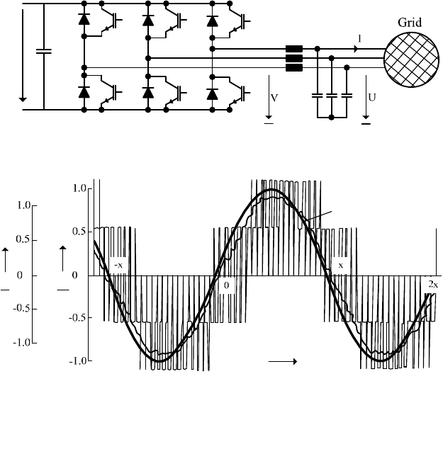
Inverters feed from a direct current grid or intermediate circuit into an AC circuit
or a three-phase grid. Again, a bridge connection of six semiconductor valves is
used, Fig. 11-32. By suitable turning on and off of the valves the intermediate cir-
cuit voltage is passed via a throttle (inductor) to the AC side. Since the current in
the inductor cannot make jumps, the AC side shows more or less sinusoidal curves
for current and voltage. Instead of the power transistors in Fig. 11-32, GTOs or
thyristors can be used here. Due to the then lower switching frequencies the devia-
tion from the sinusoidal shape is then larger, and higher harmonics are produced,
which are not wanted in the grid. Therefore, one will choose circuits which generate
less higher harmonics.
Step-up or step-down converter: If the voltage levels of the grid differs too
much, a direct feeding via a rectifier or inverter is not possible. In this case the
voltage level is adapted on the DC side using a direct current chopper, often called
step-up (booster) or step-down (buck) converter.
DC
U
U
X
1
T
2
T
3
T
4
T
5
T
6
T
1
1
ˆ
i
i
1
ˆ
u
u
t
Z
1
i
1
v
1
u
Fig. 11-32 Top: three-phase A.C. converter connected to the grid via six IGBTs with integrated
free-wheeling diodes [9]; bottom: voltage and current and pulse width modulation [9]
11 Wind turbines for electricity generation - basics
397
C
T
L
1
i
Load
U
i
t
1
i
Steering impulse
U
2
U
1
U
1
U
2
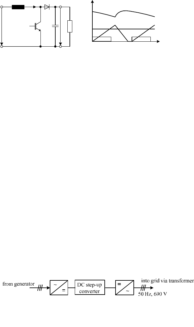
Fig. 11-33 Step-up converter (D.C. boosting unit)
The basic configuration of a step-up converter is shown in Fig. 11-33. The direct
voltage source is applied to a series connection of inductor, diode and load where
a power transistor is in parallel to diode and load. When the transistor is conduct-
ing current flows through inductor and transistor.
If the transistor is then shut off, so that it blocks the flow of current, the induc-
tor, which cannot allow abrupt changes of current, will continue the current, which
is now forced through the diode and the load. If a voltage larger than U
1
is needed
to force the current through the load the inductor will provide the extra voltage.
By a suitable choice of the switching moments the magnitude of the direct voltage
at the load is adjusted.
Converter: Most of today’s MW class wind turbines have in the normal wind
range (approx. 4 to 12 m/s) a wind speed-dependent rotor speed and therefore
operate always with
O
opt
at the design point of the turbine’s rotor. Then, the voltage
supplied by the synchronous or induction generator has neither a frequency of 50
(or 60) Hz nor the common voltage level of 690 or 400 Volts. Therefore, the elec-
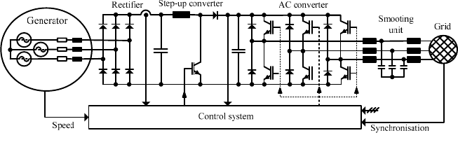
trical power has to be conditioned by an AC-DC-AC converter, Fig. 11-34.
A converter consists of a rectifier and an inverter. If required, there is an addi-
tional step-up or step-down converter. A converter is able to transfer energy of any
voltage and frequency from one grid to another grid of different voltage and fre-
quency. In addition, any desired reactive power can be fed into both grids.
Fig. 11-35 shows the basic configuration of such a converter. Grid 1 consists of
a synchronous machine. The frequency corresponds to the rotational speed of the
synchronous machine. The voltage is determined by the rotational speed as well
but it is variable within certain limits by setting the excitation of the synchronous
machine. The energy supplied by the synchronous machine is fed into a D.C.
intermediate circuit via a passive rectifier (RF) in a B6 bridge connection.
Fig. 11-34 AC-DC-AC conversion for a wind turbine
398 11.3 Power electronic components of wind turbines - converters
ZK
I
ZK
U
Grid
I
Fig. 11-35 Speed variable synchronous generator with AC-DC-AC conversion to the grid [9]
A step-up converter is integrated into the intermediate circuit. Thus energy pro-
vided at low rotational speeds low feed-in voltage levels can be used. Via the
IGBT inverter and the power chokes produced energy is fed at constant frequency
and voltage into the grid.
Multi-pole direct-drive annular synchronous generators are often switched for
variable-speed operation to a six-phase mode. Then the rectifier in Fig. 11-35
needs twelve diodes. The advantage of this arrangement is obvious: the direct
voltage has fewer harmonics, it is smoother than for a three-phase arrangement. A
more detailed discussion of application of power electronics and converter tech-
nologies is found in chapter 13.
References
[1] Nürnberg, W.: Die Prüfung elektrischer Maschinen (Testing electrical machines),
Springer Verlag, 1965
[2] Taegen, F.: Einführung in die Theorie der elektrischen Maschinen (Introduction to the
theory of electrical machines); Vol. I and II, Vieweg + Sohn Braunschweig
[3] Gerber/Hanitsch: Elektrische Maschinen (Electrical machines), Verlag Berliner
Union, Stuttgart 1980
[4] Philippow, E. (Ed.): Taschenbuch Elektrotechnik (Electrical Engineering Handbook),
Vol. 1, 2 and 5, Carl Hanser Verlag München, Wien
[5] Beitz, W., Küttner, K.-H. (Hrsg.): Dubbel, Taschenbuch für den Maschinenbau
(Handbook of Mechanical Engineering), Springer-Verlag Berlin, Heidelberg, New
York, 2002
[6] Heumann, K.: Grundlagen der Leistungselektronik (Basics on Power Electronics),
Teubner Studienbücher Stuttgart, 6th revised and extended edition, 1996
[7] Handbuch der Physik (Handbook on Physics), Vol. XVII, Verlag von Julius Springer,
Berlin 1926
[8] Fachkunde Elektrotechnik (Knowledge on Electrotechnics), Europa-Lehrmittel (Euro-
pean teaching aids), Haan-Gruiten, 22. Auflage 2000
[9] Heier, S.: Windkraftanlagen (Wind energy Converters), B.G. Teubner GmbH, Stuttgart/
Lepzig/Wiesbaden, 3rd revised and enhanced edition, 2003
[10] Fischer, R.: Elektrische Maschinen (Electrical machines), Carl Hanser Verlag,
München 1979
11 Wind turbines for electricity generation - basics
399
[11] Weh, H.: Elektrische Netzwerke und Maschinen in Matritzendarstellung (Electrical
networks and machines representd by matrices), Hochschultaschenbücherverlag,
Mannheim 1968
[12] Pfaff, G.: Regelung elektrischer Antriebe (Control of electrical drives), R. Oldenbourg
Verlag, München, Wien
[13] Fuest, K., Döring, P.: Elektrische Maschinen und Antriebe (Electrical machines and
drives), 6. Auflage, Vieweg-Verlag, Wiesbaden, 2004
[14] Quaschning, V.: Regenerative Energiesysteme(Renewable energy systems), 4th edition,
Hanser-Verlag, München, 2006
[15] Kremser, A.: Elektrische Maschinen und Antriebe (Electrical machines and drives),
2nd edition, Teubner-Verlag, Wiesbaden, 2004
[16] Quaschning, V.: Understanding renewable energy systems, 1st edition, Earthscan,
London, 2005
[17] Stiebler, M.: Wind energy systems for electric power generation, Springer-Verlag
Berlin, 2008
R. Gasch and J. Twele (eds.), Wind Power Plants: Fundamentals, Design, Construction 400
and Operation, DOI 10.1007/978-3-642-22938-1_12, © Springer-Verlag Berlin Heidelberg 2012
12 Supervisory and control systems for wind
turbines
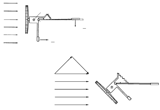
The Western mill was the first wind turbine which operated completely automatic,
“without a human supervisor”. But the tasks of the control system and the supervi-
sory system were strongly interwoven. The main vane which adjusts the rotor to
the wind direction is in fact a simple “all-in-one” control system: it is sensor to
register the deviation between the wind direction and the rotor axis, and at the
same time it is the actuator producing the forces for the correction of the deviation
from the demand value, Fig. 12-1. Together with the transverse vane it controls
the turbine in the entire operating range from standstill to storm protection: For
very strong winds the spring extends and the rotor is turned to increase the angle
between rotor axis and wind direction. Rotational speed, power extraction and
thrust are reduced, see also Fig. 12-7 (yaw angle ȕ), and annex I of this chapter. In
this annex additional examples of simple mechanical control systems for small
wind turbines are presented.
Storm position
Pivot vane
Pivot tower
)(
2
0
2
D
U
DTrans
cAv
0
D
Main vane
Lost
Component
Active
Component
)(
2
0
2
D
U
LMain
cAv
Storm position
Pivot vane
Pivot tower
)(
2
0
2
D
U
DTrans
cAv
0
D
Main vane
Lost
Component
Active
Component
)(
2
0
2
D
U
LMain
cAv
Fig. 12-1 Two-vane control of a western mill: Normal operation and power control by turning
the rotor out of the wind for strong winds
12 Supervisory and control systems for wind turbines 401
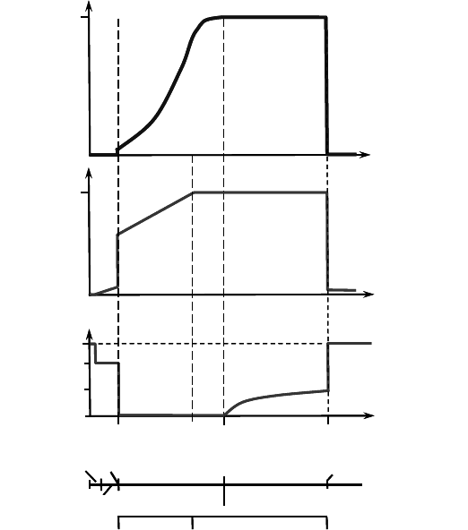
Stand still Start Partial load Full load Shut off
Variable n
R
s 10%
Speed
ElectricaL Power
P
R
Pitch angle
Wind
v
cut-in
v
R
v
cut-out
Rot. speed
85
o
65
o
25
o
0
o
Zone 1 Zone 2
4m/s
11 - 13m/s
20-25m/s
n
R
˨
=
˨
opt
˨ป˨
opt
˨
<
˨
opt
Idling Pitch const. Pitch variable Idling / Stop
Stand still Start Partial load Full load Shut off
Variable n
R
s 10%
Speed
ElectricaL Power
P
R
Pitch angle
Wind
v
cut-in
v
R
v
cut-out
Rot. speed
85
o
65
o
25
o
0
o
Zone 1 Zone 2
4m/s
11 - 13m/s
20-25m/s
n
R
˨
=
˨
opt
˨ป˨
opt
˨
<
˨
opt
Idling Pitch const. Pitch variable Idling / Stop
Fig. 12-2 Operating ranges and control of a variable-speed wind turbine with power control by
blade pitching
For today’s wind turbines of larger rotor diameters the range of functions of the
machine supervision is far more complex, e.g.: Before a grid-connected wind tur-
bine is started the following has to be checked:
- Is the oil pressure in the hydraulic systems ok?
- Are the actuators working all right?
- Is there enough wind and is it possible to supply power?
- Is there any voltage in the grid, is it possible to feed in?
- And so on.
All these checks are tasks of the supervisory system which also initiates the neces-
sary changes and maneuvers. These are for example:
- The transition from low-speed idling to grid connection in normal opera-
tion, zone 1,
- The transition from normal operation, zone 1, to strong wind operation,
zone 2,
- And so on, cf. Fig. 12-2.