Gasch R., Twele J. (Eds.) Wind Power Plants: Fundamentals, Design, Construction and Operation
Подождите немного. Документ загружается.

442 13.1 Grid-connected wind turbines
0
100
200
300
400
500
600
700
800
02468101214161820
Wind speed in m/s
Power in kW
Enercon E-40 / 6.44
Nordex N43
SÜDWIND S.46
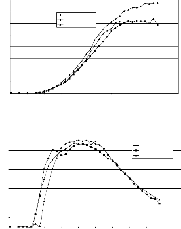
Fig. 13-12 Power curves P(v) of three different wind turbines
0,00
0,05
0,10
0,15
0,20
0,25
0,30
0,35
0,40
0,45
0,50
0 2 4 6 8 101214161820
Wind speed in m/s
Power coefficient c
P.tot
Enercon E-40 / 6.44
Nordex N43
SÜDWIND S.46
0.50
0.45
0.40
0.35
0.30
0.25
0.20
0.15
0.10
0.05
0.00
0,00
0,05
0,10
0,15
0,20
0,25
0,30
0,35
0,40
0,45
0,50
0 2 4 6 8 101214161820
Wind speed in m/s
Power coefficient c
P.tot
Enercon E-40 / 6.44
Nordex N43
SÜDWIND S.46
0.50
0.45
0.40
0.35
0.30
0.25
0.20
0.15
0.10
0.05
0.00
Fig. 13-13 Power coefficients c
P,tot
(v) of three different wind turbines
The dimensionless total power coefficients c
P.tot
reveal more. We compare first the
wind turbine of the Danish concept by NORDEX (two fixed rotor speeds) with the
ENERCON turbine which operates with variable rotor speed. For the range close
to the cut-in wind speed (3 m/s) the curves of c
P.tot
are nearly identical. Then the
NORDEX turbine shows two local optima which correspond to the design wind
speed of the “small” resp. “large” asynchronous generator. The first maximum of
13 Concepts of electricity generation by wind turbines 443
0.40 at a wind speed of approx. 5 m/s is significantly higher than the value of 0.35
for the variable-speed machine E-40. The full power conversion of the E-40
reduces its partial load efficiency significantly (at 10% of the rated power).
But for higher wind speeds the power coefficient of the E-40 which was de-
signed for variable speed is always slightly better than for the N43. At their rated
wind speed of 12 m/s the power is limited at both turbines. The N43 uses the stall
effect, the E-40 a blade pitching system. The curves of c
P.tot
are nearly identical in
this range. Since the control of the E-40 keeps the power output constant above
12 m/s there are no values shown for higher wind speeds.
The variable-speed wind turbine of SÜDWIND with a doubly-feeding asyn-
chronous generator and a converter in the rotor circuit cuts in only at 3.5 m/s,
which is barely visible in the power curve P(v). Up to a wind speed of approx.
6 m/s the curve of c
P.tot
is significantly below the curves of the N43 and E-40. In
the range between 6 and 9.5 m/s it is slightly above the values of the E-40. Both
reach a maximum efficiency of c
P.tot
= 0.45. Since the control limits the power in
the strong wind range above the rated wind speed the differences are negligible.
In general, it can be stated that despite the differences in the three wind turbine
concepts the c
P.tot
curves are astonishingly similar, except for differences in cut-in
wind speeds. The maximum power coefficient of the “primitive” Danish wind tur-
bine is only 2 percentage points below that of the wind turbines with a blade pitch-
ing system and variable rotational speed.
Thus, the relevant advantages of the modern variable-speed concepts are not
found in their efficiency, but in
- The reduction of power fluctuations during gusts,
- Significant relief for the structure in the strong wind range,
- The flexibility in adjusting the reactive power,
- The adaptation of the blade tip speed to local conditions “by pressing of a
button”, etc.
In summary: we gain increased flexibility with regard to the actual on-site condi-
tions.
13.2 Wind turbines for stand-alone operation
The most common stand-alone applications of wind turbines are the battery
charger and the wind pump. Stand-alone wind turbines eke out a niche existence
in Western Europe due to the omnipresent electrical grid. But they are of great
practical importance in the rest of the world. In Mongolia, e.g., the nomads oper-
ate thousands of battery chargers providing electricity for light and television.
444 13.2 Wind turbines for stand-alone operation
13.2.1 Battery chargers
Battery chargers have small power ratings. Typical values range from a few watts
to approx. 1.5 kW. This implies small rotor diameters (0.5 to 3.0 m), and relatively
high rotor speeds. The gearbox which is usually necessary between generator and
rotor is not needed here. Directly driven synchronous generators with a medium or
large number of poles (8 to 20 poles) are used.
For the selection of the aerodynamic profiles the low Reynolds numbers of the
flow around the blades have to be taken into account (Re = w c/
Q
< 100 000). Suit-
able profiles for this range are found in catalogues of aerodynamic profiles for
model airplanes (e.g. [4] in chapter 5 of this book).
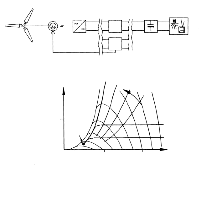
In order to determine the stationary operating behaviour, the familiar equivalent
circuit diagram of the AC synchronous machine is extended to include the load
and the rectifier (RF). Fig. 13-14b shows the resulting load curves. Below the
threshold speed, the generator voltage is lower than the sum of the voltage pro-
vided by battery charger and rectifier. Hence, there is no power output. Above the
threshold speed, there is a steep increase in power transfer, similar to the power
curve of the synchronous machine with a resistive load, see section 11.1, Fig.
11-9.
For a battery charger with a constant load, two types of operation can be distin-
guished. For low wind speeds, the battery provides the largest part of the required
power. The wind turbine operates at its power optimum (A) if it is a well designed
machine. For high wind speeds or small loads, the energy output of the wind tur-
bine exceeds the demand of the load, and has to be limited (B), therefore.
For a generator with an excitation winding, this can be achieved by adjusting
the excitation current so that the critical battery voltage is reached, but not ex-
ceeded. Fig. 13-14b shows that the power consumption is then limited, and that
the wind turbine gradually transitions to idling for higher wind speeds. If the rotor
is designed with a high tip speed ratio, limiting measures for the rotational speed
are required, e.g. by tilting, see Fig.12-19 in chapter 12.
Small battery chargers which use permanent magnets for the excitation have no
need for control of the charging current. In this case, the charging power is simply
limited by the value of the generator inductance (Fig. 11-9) or by an additional in-
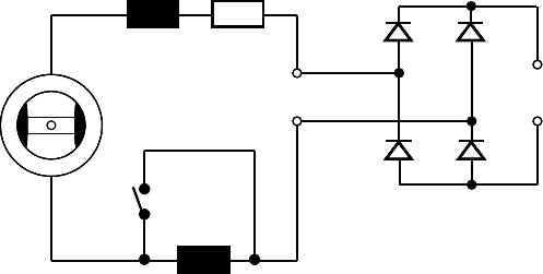
ductance connected in series, Fig. 13-15. For these components, the impedance
(X
Z
= :L
add
) increases with the frequency. In this way the battery charging cur-
rent is limited. This arrangement is shown in Fig. 13-15. If the battery storage is
large in relation to the installed generator capacity, an overcharging of the battery
is hardly possible.
In order to make better use of the advantages of excitation with permanent
magnets (good efficiency and low wear), devices from power electronics have to
be incorporated. Due to the constant excitation of the synchronous generator, the
generated voltage is proportional to the rotational speed.
13 Concepts of electricity generation by wind turbines 445
For high speeds, this voltage exceeds the rated charging voltage of the battery sub-
stantially. A step-down converter [4] is used to convert this high DC voltage to the
lower voltage level needed for the battery. Generator and battery voltage are then
decoupled, and the battery charging current can be adjusted to reasonable values
in accordance with the available power and the needs of the battery
RF step down converter consumer
Battery DC grid
storage
Field controller
CO 2
CO 1
or
P [W]
500
600 n [rpm]
B
B
I
ex
; T
o
increases
A
A: P
load
> P
R
Operation with constant
excitation close to the
turbine optimum power
B: P
load
< P
R
Limiting the power input when the battery is
full
CO1: Reduction of the exciting current (I
ex
)
CO2: Reduction of operating time (T
o
)
Charging
begins
a)
b)
RF step down converter consumer
Battery DC grid
storage
Field controller
CO 2
CO 1
or
P [W]
500
600 n [rpm]
B
B
I
ex
; T
o
increases
A
A: P
load
> P
R
Operation with constant
excitation close to the
turbine optimum power
B: P
load
< P
R
Limiting the power input when the battery is
full
CO1: Reduction of the exciting current (I
ex
)
CO2: Reduction of operating time (T
o
)
Charging
begins
a)
b)
Fig. 13-14 Battery charger, a) Block diagram; CO 1 = Controller for a generator with a field
winding excitation, CO 2 = Controller for a permanent-excited generator, b) Load curves of a
battery charger
446 13.2 Wind turbines for stand-alone operation
L
add
Thermo
switch
L
i
R
i
N S
+
~
=
RF
SC
L
add
Thermo
switch
L
i
R
i
N S
+
N S
+
~
=
RF
SC
Fig. 13-15 Battery charger with a thermo element to switch in an additional inductance at high
power levels; synchronous generator with excitation by permanent magnets
13.2.2 Resistive heaters with synchronous generators
Resistive heaters can be used to convert electric energy into thermal energy, for
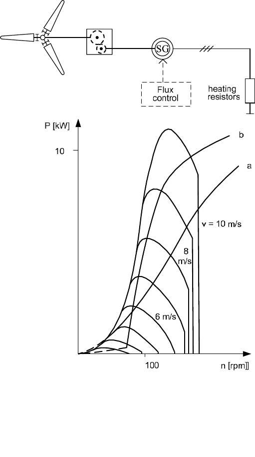
instance to make hot water. The block diagram in Fig. 13-16 shows the rather
simple layout of such a system. It consists of a wind turbine rotor with only a sim-
ple speed limitation, of a synchronous generator (SG) with gearbox, and of the
corresponding resistors. How well the optimum load curve of the wind turbine is
matched can be influenced through the excitation and the load resistors.
For a machine with constant excitation, the relationships derived in chapter 11
for the alternator remain valid (cf. Fig. 11-9). For low rotational speeds the load
curve is almost a parabola. After reaching the rated torque, the torque decreases,
but power, voltage and current continue to rise, albeit more slowly. The power
output of the wind turbine is well utilized in a wide range, Fig. 13-16, curve a.
It is often observed that wind turbines, which drive a generator, that has a per-
manent magnetic field, require wind speeds to be quite high, before they start turn-
ing. The culprit behind this is the “magnetic latching”, i.e. the rotor appears to be
locked into a rest position and needs torque to break loose. This possible short-
coming can be dealt with during the design of the generator.
The demand for quickly increasing electrical power is another detriment to
start-up at low wind speeds. This can be remedied by initially disconnecting the
load.
Self-excited synchronous machines do not have this problem, since excitation
only starts above a minimum rotational speed. Their load curve is steeper since the
excitation current is caused by the stator voltage which increases with the rota-
13 Concepts of electricity generation by wind turbines 447
tional speed. The exact curve is somewhat influenced by the selected controller
type. It will, however, always be quite similar to the curve b in Fig. 13-16.
Fig. 13-16 Wind turbine for heating, speed control by centrifugal pitch, block diagram and load
curves: a) generator with permanent magnetic field, b) self-excited generator
448 13.2 Wind turbines for stand-alone operation
13.2.3 Wind pump system with electrical power transmission
Wind pump systems with electrical power transmission have some advantages
compared to systems with direct mechanical coupling, but a lower wind pump ef-
ficiency has to be accepted. However, a more suitable site for the wind turbine can
now be chosen because it is possible that well and turbine are at separate loca-
tions. Moreover, for deep well pumps (multi-stage centrifugal pumps) electrical
power transmission is more suitable than mechanical power transmission.
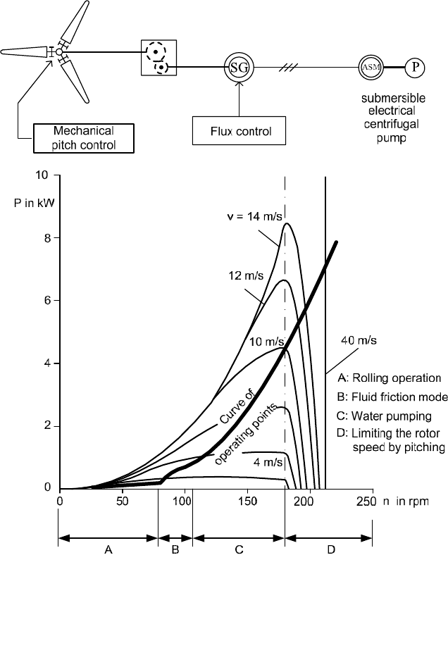
A distinction is usually made between systems with variable speed
(Fig. 13-17), and systems where the wind turbines operate at a more or less con-
stant speed (Fig. 13-18). In variable speed systems, the blade pitch limits the speed
during strong winds. In order to determine the operational behaviour, the equiva-
lent circuit diagram of the synchronous machine is used and extended by the
equivalent circuit diagram of the stationary asynchronous motor (ASM),
Fig. 11-22.
In this diagram the asynchronous motor appears as a resistive-inductive load.
The diagram leads us to the behaviour of a synchronous machine in a stand-alone
operation. However, it should be noted, that the parameters which represent the
asynchronous motor are in part a function of the rotational speed.
Fig. 13-17 shows the load curve of a wind pumping system operating at vari-
able speeds with a self-excited synchronous generator. Four ranges of operation
can be distinguished:
A Low-speed idling of the rotor, power consumption
determined by the friction in the bearings and gearbox, etc.
B Generator delivers voltage: pump acts as fluid friction dynamometer since
the rotational speed is not sufficient to overcome the geodetic head
C Water pumping: operation of the wind pump close to optimal wind
turbine power output
D Speed and power limitation: by a centrifugal pitch control
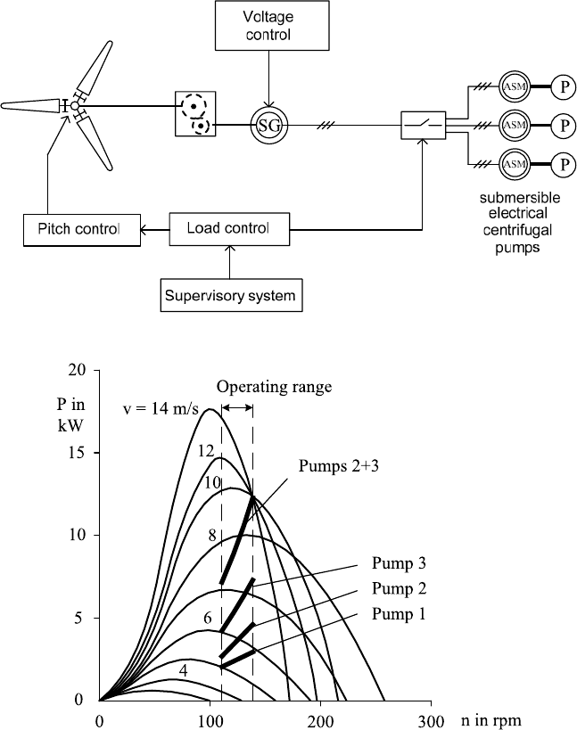
Fig. 13-18 shows a wind pumping system with electrical power transmission that
operates in a very narrow range of speeds. The pitch-controlled wind turbine
MAN-Aeroman was basically designed for grid-connected operation. As the speed
range is very narrow, the electrical machine and the centrifugal pump always work
close to their rated operating points. The layout of the system is, therefore, com-
paratively easy, but the engineering and control effort is substantial.
When the wind speed changes, pumps are switched on or off in order to adapt
to the current supply of energy. Above 10 m/s, the fast pitch control leads to a
constant power output. As an alterative to pitch control, a stall control may be
used to limit the power. In that case, the wind turbine’s speed is limited by con-
necting a controllable heater, if the maximum allowed pump power would other-
wise be exceeded.
13 Concepts of electricity generation by wind turbines 449
Fig. 13-17 Wind pumping system operating with variable rotor speeds, a) Block diagram,
b) Load curve
450 13.2 Wind turbines for stand-alone operation
Fig. 13-18 Wind pumping system operating at nearly constant rotor speed by switching the
pumps, a) Block diagram, b) Load curve
13 Concepts of electricity generation by wind turbines 451
13.2.4 Stand-alone wind turbines for insular grids
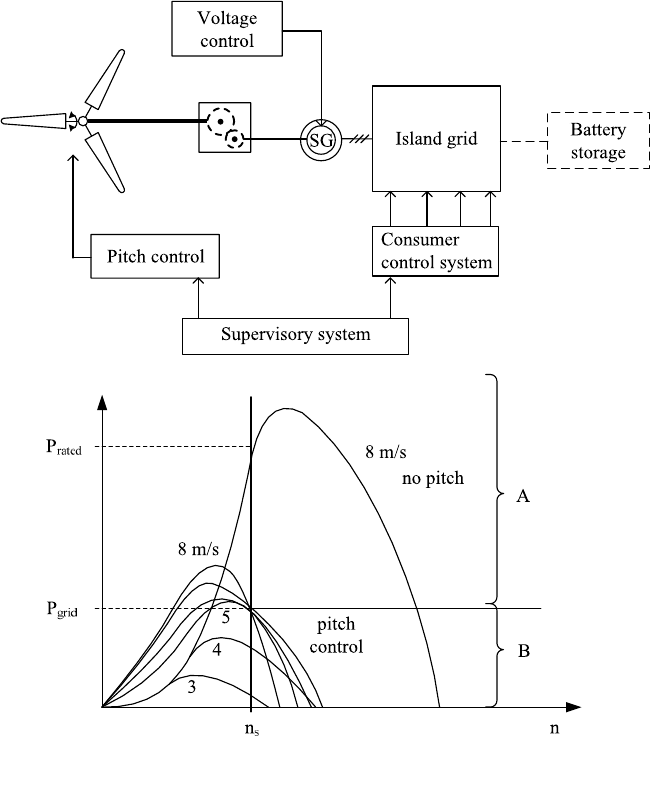
When feeding insular or local grids, a wind turbine supplies a fairly constant fre-
quency and voltage for isolated consumers, e.g. alpine huts, farms, or rural com-
munities in the Third World. In this application, the supply of both active and re-
active power is required, and voltage control is necessary. Therefore, synchronous
generators (SG) are suitable. A fairly stable frequency is achieved by switching
consumers on and off. A stall-controlled turbine combined with an adjustable
heater or a fast pitch control is used.
Fig. 13-19 Wind turbine with pitch control and consumer control system for stand-alone opera-
tion, a) Block diagram, b) Load curve
