Fitzgerald A.E. Electric Machinery
Подождите немного. Документ загружается.

116 CHAPTER 3
ElectromechanicaI-Energy-Conversion Principles
which act to squash or deform the rotor, play no significant role in the performance
of the motor and generally are not calculated.
To understand the behavior of rotating machinery, a simple physical picture is
quite useful. Associated with the rotor structure is a magnetic field (produced in
many machines by currents in windings on the rotor), and similarly with the stator;
one can picture them as a set of north and south magnetic poles associated with each
structure. Just as a compass needle tries to align with the earth's magnetic field, these
two sets of fields attempt to align, and torque is associated with their displacement
from alignment. Thus, in a motor, the stator magnetic field rotates ahead of that of
the rotor, pulling on it and performing work. The opposite is true for a generator, in
which the rotor does the work on the stator.
Various techniques have evolved to calculate the net forces of concern in the
electromechanical-energy-conversion process. The technique developed in this chap-
ter and used throughout the book is known as the
energy method
and is based on
the principle of
conservation of energy.
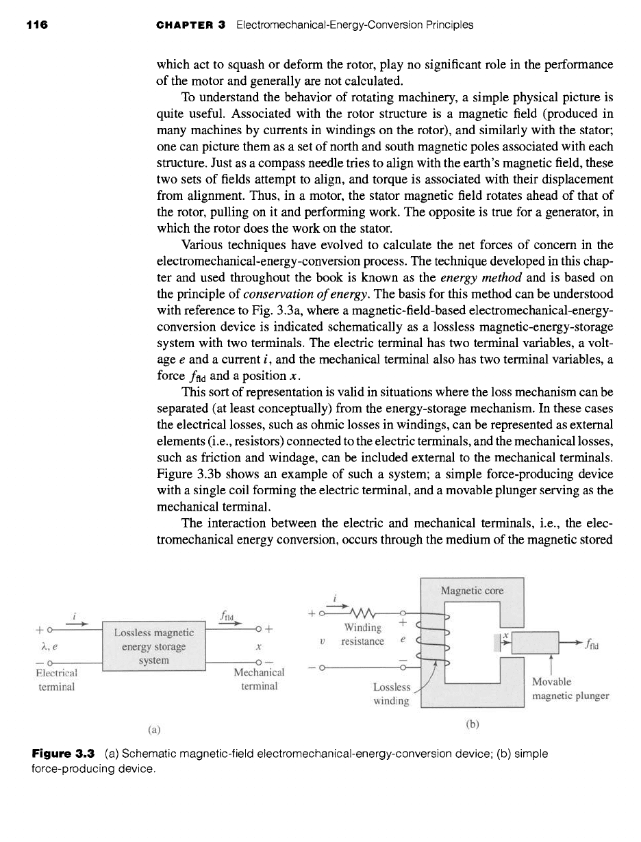
The basis for this method can be understood
with reference to Fig. 3.3a, where a magnetic-field-based electromechanical-energy-
conversion device is indicated schematically as a lossless magnetic-energy-storage
system with two terminals. The electric terminal has two terminal variables, a volt-
age e and a current i, and the mechanical terminal also has two terminal variables, a
force ffld and a position x.
This sort of representation is valid in situations where the loss mechanism can be
separated (at least conceptually) from the energy-storage mechanism. In these cases
the electrical losses, such as ohmic losses in windings, can be represented as external
elements (i.e., resistors) connected to the electric terminals, and the mechanical losses,
such as friction and windage, can be included external to the mechanical terminals.
Figure 3.3b shows an example of such a system; a simple force-producing device
with a single coil forming the electric terminal, and a movable plunger serving as the
mechanical terminal.
The interaction between the electric and mechanical terminals, i.e., the elec-
tromechanical energy conversion, occurs through the medium of the magnetic stored
i
ffld
-Jr- 0 /W~ , Ol-
+ + Winding
-1-(
v resistance e ¢
m m m C
Electrlca~ ~vtecnanical -- o o----
terminal terminal Lossless 1
winding
(a)
Magnetic cot
.......
.........
I \] Movable
..... ] magnetic plunger
(b)
Figure 3.3 (a) Schematic magnetic-field electromechanical-energy-conversion device; (b) simple
force-producing device.
3.2 Energy Balance 117
energy. Since the energy-storage system is lossless, it is a simple matter to write that
the time rate of change of Wild, the stored energy in the magnetic field, is equal to the
electric power input (given by the product of the terminal voltage and current) less
the mechanical power output of the energy storage system (given by the product of
the mechanical force and the mechanical velocity)"
dWfld dx
= ei
- ffld~
(3.7)
dt dt
Recognizing that, from Eq. 1.27, the voltage at the terminals of our lossless
winding is given by the time-derivative of the winding flux linkages
d~,
e = (3.8)
dt
and multiplying Eq. 3.7 by
dt,
we get
dWnd = i d)~ -
fnd
dx
(3.9)
As shown in Section 3.4, Eq. 3.9 permits us to solve for the force simply as a
function of the flux ~. and the mechanical terminal position x. Note that this result
comes about as a consequence of our assumption that it is possible to separate the
losses out of the physical problem, resulting in a lossless energy-storage system, as
in Fig. 3.3a.
Equations 3.7 and 3.9 form the basis for the energy method. This technique is quite
powerful in its ability to calculate forces and torques in complex electromechanical-
energy-conversion systems. The reader should recognize that this power comes at the
expense of a detailed picture of the force-producing mechanism. The forces them-
selves are produced by such well-known physical phenomena as the Lorentz force on
current carrying elements, described by Eq. 3.6, and the interaction of the magnetic
fields with the dipoles in the magnetic material.
3.2 ENERGY BALANCE
The principle of conservation of energy states that energy is neither created nor
destroyed; it is merely changed in form. For example, a golf ball leaves the tee with a
certain amount of kinetic energy; this energy is eventually dissipated as heat due to air
friction or rolling friction by the time the ball comes to rest on the fairway. Similarly,
the kinetic energy of a hammer is eventually dissipated as heat as a nail is driven into
a piece of wood. For isolated systems with clearly identifiable boundaries, this fact
permits us to keep track of energy in a simple fashion: the net flow of energy into the
system across its boundary is equal to the sum of the time rate of change of energy
stored in the system.
This result, which is a statement of the first law of thermodynamics, is quite
general. We apply it in this chapter to electromechanical systems whose predominant
energy-storage mechanism is in magnetic fields. In such systems, one can account for

118 CHAPTER 3
ElectromechanicaI-Energy-Conversion Principles
energy transfer as
(Energy input~ fMechanical )/Increase in energy~ fEnergy ~
from electric] - ~energy + ~stored in magnetic) + ~convertedJ
sources / \output \field \into heat /
(3.10)
Equation 3.10 is written so that the electric and mechanical energy terms have positive
values for motor action. The equation applies equally well to generator action: these
terms then simply have negative values. In either case, the sign of the heat generation
term is such that heat generation within the system results in a flow of thermal energy
out of the system.
In the systems which we consider here, the conversion of energy into heat occurs
by such mechanisms as ohmic heating due to current flow in the windings of the
electric terminals and mechanical friction due to the motion of the system compo-
nents forming the mechanical terminals. As discussed in Section 3.1, it is generally
possible to mathematically separate these loss mechanisms from the energy-storage
mechanism. In such cases, the device can be represented as a lossless magnetic-
energy-storage system with electric and mechanical terminals, as shown in Fig. 3.3a.
The loss mechanisms can then be represented by external elements connected to
these terminals, resistances to the electric terminals, and mechanical dampers to the
mechanical terminals. Figure 3.3a can be readily generalized to situations with any
number of electric or mechanical terminals. For this type of system, the magnetic
field serves as the coupling medium between the electric and mechanical terminals.
The ability to identify a lossless-energy-storage system is the essence of the
energy method. It is important to recognize that this is done mathematically as part
of the modeling process. It is not possible, of course, to take the resistance out of
windings or the friction out of bearings. Instead we are making use of the fact that a
model in which this is done is a valid representation of the physical system.
For the lossless magnetic-energy-storage system of Fig. 3.3a, rearranging Eq. 3.9
in the form of Eq. 3.10 gives
d
Welec --
d
Wmech -~-
d
Wil d (3.11)
where
dWelec = i d~. = differential electric energy input
d
Wmech "-- ffld
dx =
differential mechanical energy output
d Wfld
= differential change in magnetic stored energy
From Eq. 3.8, we can write
dWelec "-
ei dt
(3.12)
Here e is the voltage induced in the electric terminals by the changing magnetic stored
energy. It is through this reaction voltage that the external electric circuit supplies
power to the coupling magnetic field and hence to the mechanical output terminals.
Thus the basic energy-conversion process is one involving the coupling field and its
action and reaction on the electric and mechanical systems.
3.3 Energy in Singly-Excited Magnetic Field Systems 119
Combining Eqs. 3.11 and 3.12 results in
dWelec --
ei dt
= dWmech d-
dWfld
(3.13)
Equation 3.13, together with Faraday's law for induced voltage (Eq. 1.27), form
the basis for the energy method; the following sections illustrate its use in the analysis
of electromechanical-energy-conversion devices.
3.3 ENERGY IN SINGLY-EXCITED MAGNETIC
FIELD SYSTEMS
In Chapters 1 and 2 we were concerned primarily with fixed-geometry magnetic
circuits such as those used for transformers and inductors. Energy in those devices is
stored in the leakage fields and to some extent in the core itself. However, the stored
energy does not enter directly into the transformation process. In this chapter we are
dealing with energy-conversion systems; the magnetic circuits have air gaps between
the stationary and moving members in which considerable energy is stored in the
magnetic field. This field acts as the energy-conversion medium, and its energy is the
reservoir between the electric and mechanical systems.
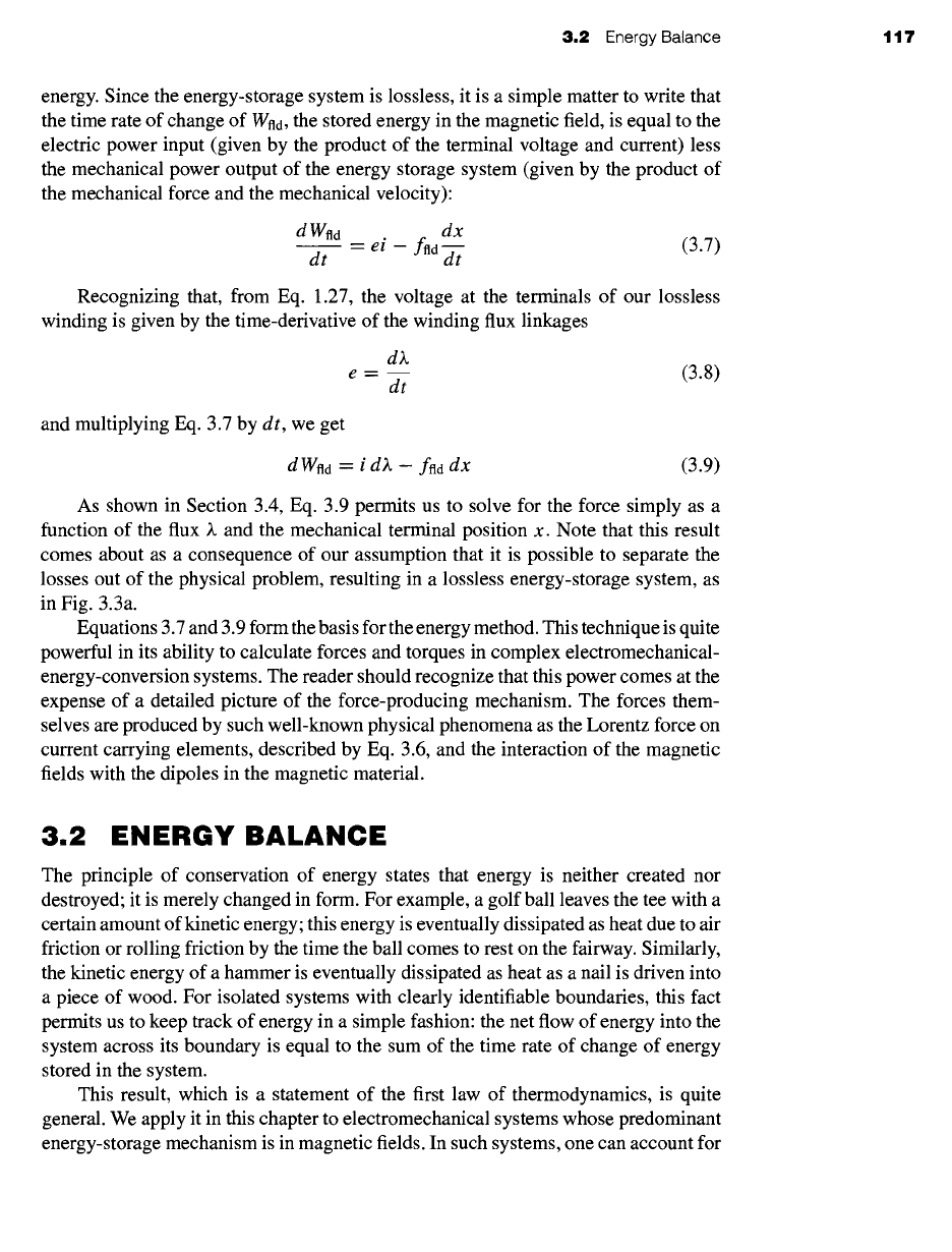
Consider the electromagnetic relay shown schematically in Fig. 3.4. The resis-
tance of the excitation coil is shown as an external resistance R, and the mechanical
terminal variables are shown as a force
fnd
produced by the magnetic field directed
from the relay to the external mechanical system and a displacement x; mechanical
losses can be included as external elements connected to the mechanical terminal.
Similarly, the moving armature is shown as being massless; its mass represents me-
chanical energy storage and can be included as an external mass connected to the
mechanical terminal. As a result, the magnetic core and armature constitute a lossless
magnetic-energy-storage system, as is represented schematically in Fig. 3.3a.
This relay structure is essentially the same as the magnetic structures analyzed in
Chapter 1. In Chapter 1 we saw that the magnetic circuit of Fig. 3.4 can be described by
an inductance L which is a function of the geometry of the magnetic structure and the
+
v(
R i
ii] x ~1
"-I
,.~ Mechanical
ffld source
-- t
Electrical
source
~, e
m
Lossless
coil
Magnetic core
~ Massless
magnetic
armature
Figure
3.4 Schematic of an electromagnetic relay.
120 CHAPTER 3
ElectromechanicaI-Energy-Conversion Principles
permeability of the magnetic material. Electromechanical-energy-conversion devices
contain air gaps in their magnetic circuits to separate the moving parts. As discussed in
Section 1.1, in most such cases the reluctance of the air gap is much larger than that of
the magnetic material. Thus the predominant energy storage occurs in the air gap, and
the properties of the magnetic circuit are determined by the dimensions of the air gap.
Because of the simplicity of the resulting relations, magnetic nonlinearity and
core losses are often neglected in the analysis of practical devices. The final results
of such approximate analyses can, if necessary, be corrected for the effects of these
neglected factors by semi-empirical methods. Consequently, analyses are carried out
under the assumption that the flux and mmf are directly proportional for the entire
magnetic circuit. Thus the flux linkages ~. and current i are considered to be linearly
related by an inductance which depends solely on the geometry and hence on the
armature position x.
~. = L(x)i
(3.14)
where the explicit dependence of L on x has been indicated.
Since the magnetic force ftd has been defined as acting from the relay upon the
external mechanical system and
d Wmech
is defined as the mechanical energy output
of the relay, we can write
dWmech = ftd
dx
(3.15)
Thus, using Eq. 3.15 and the substitution dWelec = i d~., we can write Eq. 3.11 as
dWfld = i d)~ - ftd dx
(3.16)
Since the magnetic energy storage system is lossless, it is a
conservative system
and the value of Wild is uniquely specified by the values of Z and x; ~. and x are thus
referred to as
state variables
since their values uniquely determine the state of the
system.
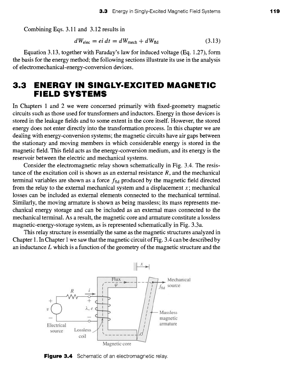
From this discussion we see that Wild, being uniquely determined by the values
of ~ and
x, is the same regardless of how )~ and x are brought to their final values.
Consider Fig. 3.5, in which two separate paths are shown over which Eq. 3.16 can be
integrated to find Wild at the point (~.0, x0). Path 1 is the general case and is difficult to
~'o
Wnd (Z.O, %)
2b
-2a Xo
Figure 3.5
Integration paths
for ~ld.
3.3 Energy in Singly-Excited Magnetic Field Systems 121
integrate unless both i and fnd are known explicitly as a function of)~ and x. However,
because the integration of Eq. 3.16 is path independent, path 2 gives the same result
and is much easier to integrate. From Eq. 3.16
Wnd(Xo, xo) = f dWnd + f dWnd
(3.17)
path 2a path 2b
Notice that on path 2a, d)~ = 0 and
ffld "--
0 (since ~. = 0 and there can be no magnetic
force in the absence of magnetic fields). Thus from Eq. 3.16, d Wfld = 0 on path 2a.
On path 2b, dx = 0, and, thus, from Eq. 3.16, Eq. 3.17 reduces to the integral of i d)~
over path 2b (for which x = x0).
fO L°
Wfld()~0, X0) =
i(~, x0) d~ (3.18)
For a linear system in which )~ is proportional to i, as in Eq. 3.14, Eq. 3.18 gives
j~o ;~ ~o x U 1 ~2
Wfld(~,,
X) --
i(X', x) dU = L(x) dU = 2 L(x) (3.19)
It can be shown that the magnetic stored energy can also be expressed in terms of
the energy density of the magnetic field integrated over the volume V of the magnetic
field. In this case
(J0")
Wild
:
H. dB' dV (3.20)
For soft magnetic material of constant permeability (B =/zH), this reduces to
/, (")
Wild= ~ dV (3.21)
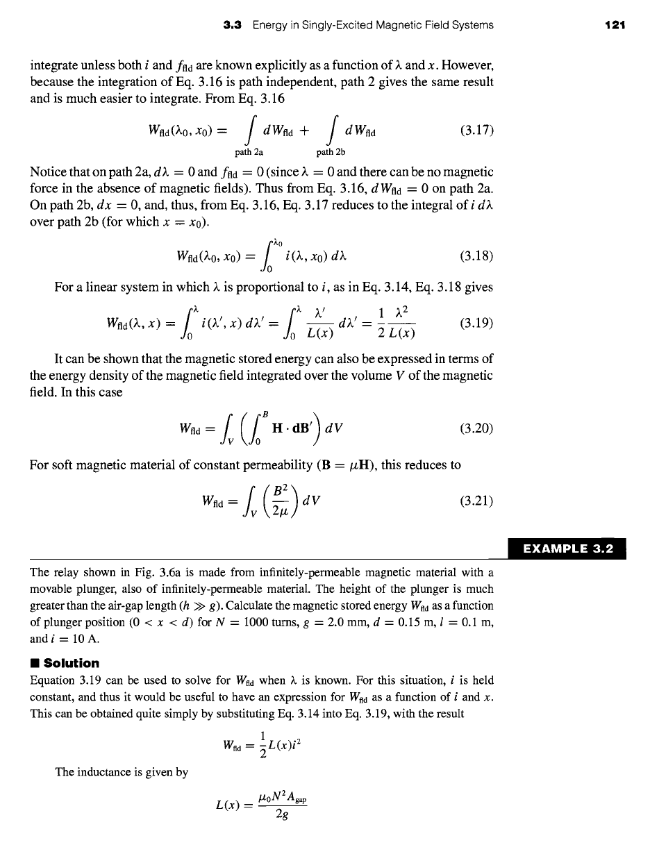
The relay shown in Fig. 3.6a is made from infinitely-permeable magnetic material with a
movable plunger, also of infinitely-permeable material. The height of the plunger is much
greater than the air-gap length (h >> g). Calculate the magnetic stored energy Wad as a function
of plunger position (0 < x < d) for N = 1000 turns, g = 2.0 mm, d = 0.15 m, l = 0.1 m,
and i = 10 A.
II Solution
Equation 3.19 can be used to solve for Wnd when ~. is known. For this situation, i is held
constant, and thus it would be useful to have an expression for Wnd as a function of i and x.
This can be obtained quite simply by substituting Eq. 3.14 into Eq. 3.19, with the result
1
Wftd = ~ L(x)i 2
The inductance is given by
L(x) =
/Zo N2 Agap
2g
EXAMPLE 3.2
122 CHAPTER 3
ElectromechanicaI-Energy-Conversion Principles
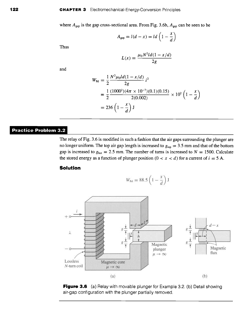
where Agap is the gap cross-sectional area. From Fig. 3.6b, Agap can be seen to be
agap = l(d - x) = ld (1- d)
Thus
and
L(x) = lz°N21d(1 - x/d)
2g
1 N2lzold(1 - x/d)
i2
w.. = ~
2g
1 (10002)(4n x 10-7)(0.1)(0.15) ( x)
2(0.002) x 102 1 -
= 236 (1- d) J
)ractice Problem 3.:
The relay of Fig. 3.6 is modified in such a fashion that the air gaps surrounding the plunger are
no longer uniform. The top air gap length is increased to gtop -- 3.5 mm and that of the bottom
gap is increased to gbot
"-
2.5 mm. The number of turns is increased to N = 1500. Calculate
the stored energy as a function of plunger position (0 < x < d) for a current of i = 5 A.
Solution
(x)
Wnd=88.5 1--~ J
J
i
+~
Lossless
N-turn coil
(a) (b)
Figure 3.6 (a) Relay with movable plunger for Example 3.2. (b) Detail showing
air-gap configuration with the plunger partially removed.
3.4 Determination of Magnetic Force and Torque from Energy 123
In this section we have seen the relationship between the magnetic stored energy
and the electric and mechanical terminal variables for a system which can be repre-
sented in terms of a lossless-magnetic-energy-storage element. If we had chosen for
our example a device with a rotating mechanical terminal instead of a linearly dis-
placing one, the results would have been identical except that force would be replaced
by torque and linear displacement by angular displacement. In Section 3.4 we see
how knowledge of the magnetic stored energy permits us to solve for the mechanical
force and torque.
3.4 DETERMINATION OF MAGNETIC FORCE
AND TORQUE FROM ENERGY
As discussed in Section 3.3, for a lossless magnetic-energy-storage system, the mag-
netic stored energy
Wild
is a state function, determined uniquely by the values of
the independent state variables ~. and x. This can be shown explicitly by rewriting
Eq. 3.16 in the form
dWfld(~,, x) =
i d)~
- ffld
dx
(3.22)
For any state function of two independent variables, e.g., F(Xl, x2), the total
differential of F with respect to the two state variables X l and x2 can be written
OF dxl + ~ dx2 (3.23)
dF(xl, x2) = ~ x2 x,
It is extremely important to recognize that the partial derivatives in Eq. 3.23 are each
taken by holding the opposite state variable constant.
Equation 3.23 is valid for any state function F and hence it is certainly valid for
Wnd; thus
0 Wild 0 Wild
dWfld(~., x) -- d~. + dx (3.24)
8~. x dx
Since k and x are independent variables, Eqs. 3.22 and 3.24 must be equal for all
values of d~ and dx, and so
i .__
own~(Z,x)
(3.25)
where the partial derivative is taken while holding x constant and
0 Wfld(/~, X)
fro = -- (3.26)
Ox z
in this case holding )~ constant while taking the partial derivative.
This is the result we have been seeking. Once we know
Wild as
a function of )~
and x, Eq. 3.25 can be used to solve for i (~., x). More importantly, Eq. 3.26 can be
used to solve for the mechanical force ffld (~, x). It cannot be overemphasized that the
partial derivative of Eq. 3.26 is taken while holding the flux linkages ~. constant. This
124 CHAPTER 3
ElectromechanicaI-Energy-Conversion Principles
is easily done provided W~d is a known function of ~. and x. Note that this is purely
a mathematical requirement and has nothing to do with whether Z is held constant
when operating the actual device.
The force ffld is determined from Eq. 3.26 directly in terms of the electrical state
variable ~.. If we then want to express the force as a function of i, we can do so by
substituting the appropriate expression for ~. as a function of i into the expression for
fna that is obtained by using Eq. 3.26.
For linear magnetic systems for which ~. =
L(x)i,
the energy is expressed by
Eq. 3.19 and the force can be found by direct substitution in Eq. 3.26
Ofl)~2~
_ ~.2
dL(x)
\)
ffld --
Ox -2 L(x) ;~
2L(x) 2
dx
(3.27)
If desired, the force can now be expressed in directly in terms of the current i simply
by substitution of ~. --
L(x)i
i 2 dL(x)
f~d = 2 dx
(3.28)
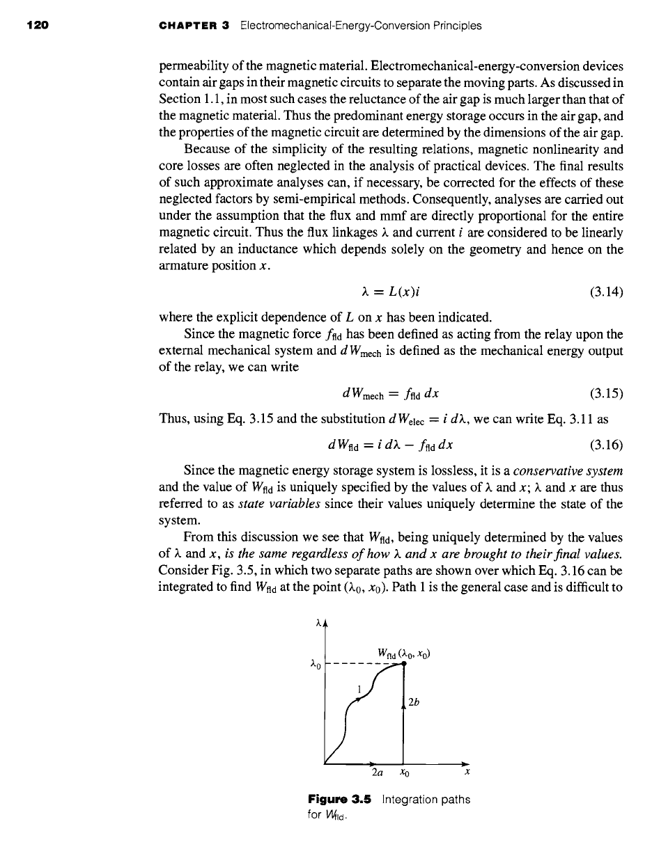
"XAMPLE 3.,
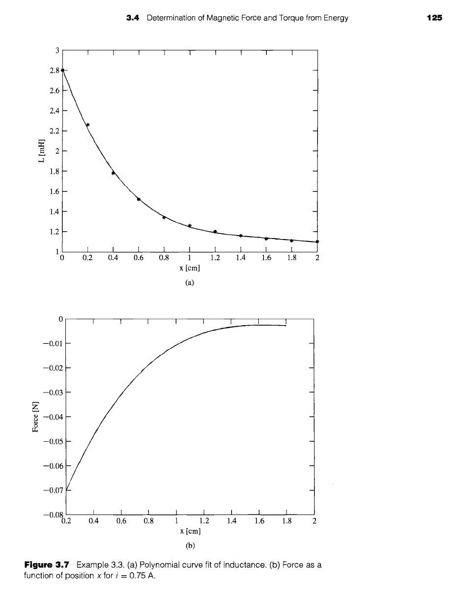
Table 3.1 contains data from an experiment in which the inductance of a solenoid was measured
as a function of position x, where x = 0 corresponds to the solenoid being fully retracted.
Table 3.1
Data for Example
3.3.
.|ll
x [cm] 0 0.2 0.4 0.6 0.8 1.0 1.2 1.4 1.6 1.8 2.0
L [mH] 2.8 2.26 1.78 1.52 1.34 1.26 1.20 1.16 1.13 1.11 1.10
Plot the solenoid force as a function of position for a current of 0.75 A over the range 0.2 <
x < 1.8 cm.
D
II
Solution
The solution is most easily obtained using MATLABJ First, a fourth-order polynomial fit of
the inductance as a function of x is obtained using the MATLAB function
polyfit.
The result is
of the form
L(x)
- a(1)x 4 + a(2)x 3 + a(3)x 2 + a(4)x + a(5)
Figure 3.7a shows a plot of the data points along with the results of the polynomial fit.
Once this fit has been obtained, it is a straight forward matter to calculate the force from
Eq. 3.28.
i 2 dL(x) i 2
f,d = 2 dx
= 2 (4a(1)x3 + 3a(2)x2 + 2a(3)x + a(4))
This force is plotted in Figure 3.7b. Note that the force is negative, which means that it is acting
in such a direction as to pull the solenoid inwards towards x = 0.
t MATLAB is a registered trademark of The MathWorks, Inc.
3.4 Determination of Magnetic Force and Torque from Energy 125
2.8
2.6
2.4
2.2
1.8
1.6
1.4
1.2
I I I I I I I I I
1 I I I I I I I I I
0 0.2 0.4 0.6 0.8 1 1.2 1.4 1.6 1.8 2
x [cm]
(a)
0
-0.01
-0.02
-0.03
z
--0.04
--0.05
--0.06
--0.07
--0.08
0.2 0.4 0.6 0.8 1 1.2 1.4 1.6 1.8 2
X [cm]
(b)
Figure 3.7 Example 3.3. (a) Polynomial curve fit of inductance. (b) Force as a
function of position x for i = 0.75 A.