Fitzgerald A.E. Electric Machinery
Подождите немного. Документ загружается.

136 CHAPTER 3 ElectromechanicaI-Energy-Conversion Principles
Tnd can now be calculated as
4zr x 10-7(7860)2(1.8 x 10⁻²)(2.5 x 10 -2 -+-0.5(3 x 10⁻³))
T~a
=
4(3 x 10 -3)
= 3.09 N- m
(a) Write an expression for the inductance of the magnetic circuit of Fig. 3.12 as a function
of 0. (b) Using this expression, derive an expression for the torque acting on the rotor as a
function of the winding current i and the rotor angle 0.
Solution
L(O) =
i 2 dL(O)
Tnd = 2 dO
#oN2h(r] +
0.5g)0
2g
i2 ( txoN2h(rl + O.5g) )
=
3.6 MULTIPLY-EXCITED MAGNETIC
FIELD SYSTEMS
Many electromechanical devices have multiple electrical terminals. In measurement
systems it is often desirable to obtain torques proportional to two electric signals; a
meter which determines power as the product of voltage and current is one example.
Similarly, most electromechanical-energy-conversion devices consist of multiply-
excited magnetic field systems.
Analysis of these systems follows directly from the techniques discussed in
previous sections. This section illustrates these techniques based on a system with two
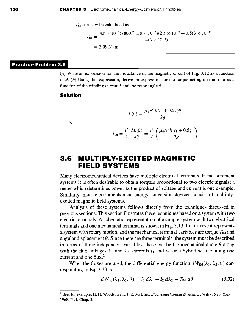
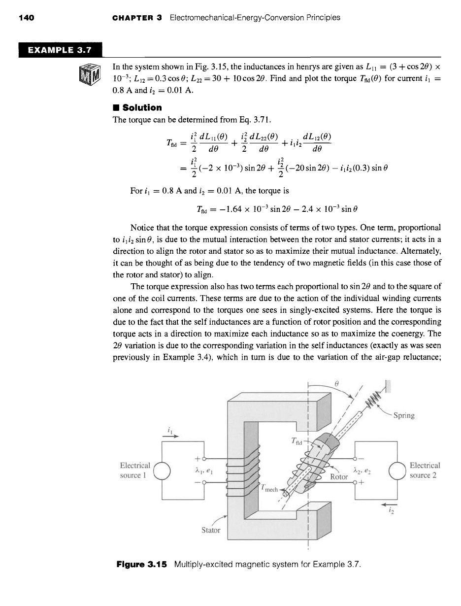
electric terminals. A schematic representation of a simple system with two electrical
terminals and one mechanical terminal is shown in Fig. 3.13. In this case it represents
a system with rotary motion, and the mechanical terminal variables are torque Tnd and
angular displacement 0. Since there are three terminals, the system must be described
in terms of three independent variables; these can be the mechanical angle 0 along
with the flux linkages X1 and X2, currents i l and i2, or a hybrid set including one
current and one flux. 2
When the fluxes are used, the differential energy function dWnd(~.l, X2, 0) cor-
responding to Eq. 3.29 is
dWnd(~.], X2, O) = il dX1 + i2 dX2 - Tfla dO
(3.52)
2 See, for example, H. H. Woodson and J. R. Melcher,
Electromechanical Dynamics,
Wiley, New York,
1968, Pt. I, Chap. 3.
3.6 Multiply-Excited Magnetic Field Systems 137
il..~
v
4-o
mo
i2
v
4-o
~.2
~o
Electric
terminals
iiiiii~~i.~ili~iiiii!i
Tfld
o+
0
o--
Mechanical
terminal
Figure 3.13 Multiply-excited magnetic energy
storage system.
and in direct analogy to the previous development for a singly-excited system
and
il
--
O Wfld()~l, ~'2, 0)
X2,0
i2 "-"
O Wfld(~.l, ~.2, 0)
0/~.2
~.l,0
(3.53)
(3.54)
0 Wfld(~l, ~.2,
0) I (3.55)
Tfld
= -- O0 ),1.),2
Note that in each of these equations,
the partial derivative with respect to each inde-
pendent variable must be taken holding the other two independent variables constant.
The energy Wild can be found by integrating Eq. 3.52. As in the singly-excited
case, this is most conveniently done by holding ~,1 and ~,2 fixed at zero and integrating
first over 0; under these conditions, Tnd is zero, and thus this integral is zero. One can
then integrate over ,k2 (while holding
~1
zero) and finally over ~.1. Thus
f
~,2 0
Wfld(~'lo, ~'20, 00) "- i2(~.1 "- 0, ~'2, 0 "- 00) d~.2
dO
f
~.l o
4- il (~,1, ~,2 = ~,20, 0 -'- 00)
d~,l
(3.56)
a0
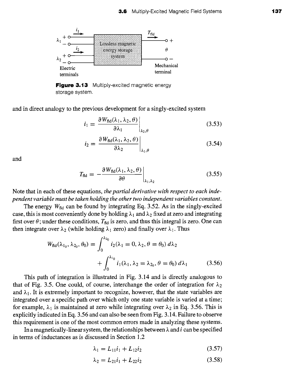
This path of integration is illustrated in Fig. 3.14 and is directly analogous to
that of Fig. 3.5. One could, of course, interchange the order of integration for
~.2
and ~.1. It is extremely important to recognize, however, that the state variables are
integrated over a specific path over which only one state variable is varied at a time;
for example,
~.1
is maintained at zero while integrating
over ~2
in Eq. 3.56. This is
explicitly indicated in Eq. 3.56 and can also be seen from Fig. 3.14. Failure to observe
this requirement is one of the most common errors made in analyzing these systems.
In a magnetically-linear system, the relationships between)~ and i can be specified
in terms of inductances as is discussed in Section 1.2
)~1 =
Lllil
+
L12i2
(3.57)
~.2 = L21il
-{- L22i2
(3.58)
138 CHAPTER 3 ElectromechanicaI-Energy-Conversion Principles
~.l 0
/
\
\
\
\
\
\
\
t Wfld(~" 1 O, ~'2 O, 00)
~.2 o
iiiiii I
k~
Figure 3.14
Integration path to
obtain ~ld(Z.10, Z.2o, eo).
where
Ll2
= L21
(3.59)
Here the inductances are, in general, functions of angular position 0.
These equations can be inverted to obtain expressions for the i's as a function of
the 0's
where
L22kl -- L12~.2
il -- (3.60)
D
--L21~.l + Lll~.2
i2 =
(3.61)
D
D = LllL22 -- L12L21
(3.62)
The energy for this linear system can be found from Eq. 3.56
f
Z2o
L ll (00)k2
Wfld(klo, k2o, 00) =
D(Oo)
dke
J0
f
;~'o (L22(00)~.1 - L12(00)~.2o)
+
dkl
,Io D(Oo)
1 1
= 2D(Oo--------~L,,(O0)~.2o -F 2D(Oo----~L22(O0)~.2o
LI2(00)
--
~klo~,2o
D(Oo)
(3.63)
where the dependence of the inductances and the determinant
D(O)
on the angular
displacement 0 has been explicitly indicated.
In Section 3.5, the coenergy function was defined to permit determination of
force and torque directly in terms of the current for a single-winding system. A
3,6
Multiply-Excited Magnetic Field Systems t39
similar coenergy function can be defined in the case of systems with two windings as
W~d(il, i2, 0) = ~.lil + ~.2i2 -- Wild (3.64)
It is a state function of the two terminal currents and the mechanical displacement.
Its differential, following substitution of Eq. 3.52, is given by
dWfld(il,
i2, 0) "- ~.1
dil + ~.2 di2 +
Tfld
dO (3.65)
From Eq. 3.65 we see that
~,2 -"
O W~d(il, i2, 0)
Oil
O W~d(il, i2, 0)
0i2
i2,0
il ,O
(3.66)
(3.67)
For such a linear system, the torque can be found either from the energy of
Eq. 3.63 using Eq. 3.55 or from the coenergy of Eq. 3.70 using Eq. 3.68. It is at
this point that the utility of the coenergy function becomes apparent. The energy
expression of Eq. 3.63 is a complex function of displacement, and its derivative is
even more so. Alternatively, the coenergy function is a relatively simple function of
displacement, and from its derivative a straightforward expression for torque can be
determined as a function of the winding currents il and i2 as
O W~d(il, i2, 0)
Tfld --
O0 il,i2
i 2 dLll(O) i 2 dLz2(O) dL12(O)
= --~ ~ + ili2~ (3.71)
2 dO 2 dO dO
O W~d(il, i2, 0)
O0
il,i2
Analogous to Eq. 3.56, the coenergy can be found as
f
t2 o
Whd(llo, 12 o,'
" " 00) = )',2(il "-- O, i2, 0 = 00)
di2
do
f
tl
+ ~.1 (il, i2 = i2o, 0 = 0o) dil
,1o
For the linear system of Eqs. 3.57 to 3.59
, . 1 1
W~d(tl, i2, 0) = -gLll(O)i 2 + -gL22(O)i 2 + L12(0)ili2
z
z,
(3.70)
Systems with more than two electrical terminals are handled in analogous fashion.
As with the two-terminal-pair system above, the use of a coenergy function of the
terminal currents greatly simplifies the determination of torque or force.
(3.68)
(3.69)
Tfld
Most significantly, the torque can now be determined directly in terms of the
currents as
140 CHAPTER 3 ElectromechanicaI-Energy-Conversion Principles
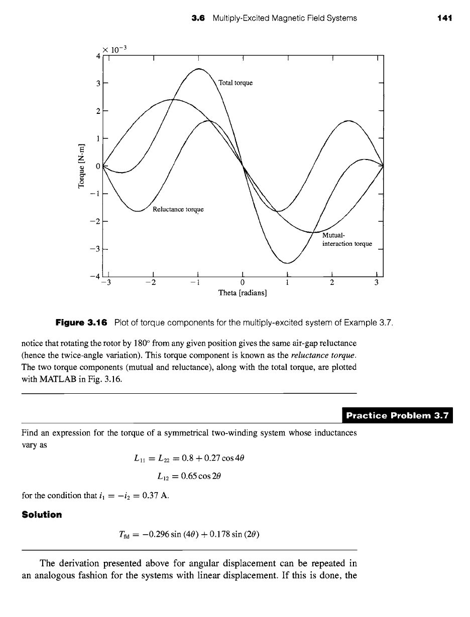
In the system shown in Fig. 3.15, the inductances in henrys are given as Lll = (3 + cos 20) x
10 -3. L12 =0.3cos0" L22 = 30 + 10cos20. Find and plot the torque Tnd(0) for current il =
0.8 A and i2 = 0.01 A.
II Solution
The torque can be determined from Eq. 3.71.
i 2 dLll(O) i 2 dL22(O) + ili2dL12(O)
T.~
-2 dO 42 dO d------~
2. i 2
= t--" (-2 x 10⁻³) sin20 + _--(-20sin20)-
ili2(0.3)sinO
2
2
For i l = 0.8 A and i2 = 0.01 A, the torque is
Tnd = -- 1.64 x 10 -3 sin 20 -- 2.4 x 10 -3 sin 0
Notice that the torque expression consists of terms of two types. One term, proportional
to
i]i2
sin 0, is due to the mutual interaction between the rotor and stator currents; it acts in a
direction to align the rotor and stator so as to maximize their mutual inductance. Alternately,
it can be thought of as being due to the tendency of two magnetic fields (in this case those of
the rotor and stator) to align.
The torque expression also has two terms each proportional to sin 20 and to the square of
one of the coil currents. These terms are due to the action of the individual winding currents
alone and correspond to the torques one sees in singly-excited systems. Here the torque is
due to the fact that the self inductances are a function of rotor position and the corresponding
torque acts in a direction to maximize each inductance so as to maximize the coenergy. The
20 variation is due to the corresponding variation in the self inductances (exactly as was seen
previously in Example 3.4), which in turn is due to the variation of the air-gap reluctance;
i, ¢
+ --
Electrical ~.l, el ' _~ ~.2, e2 ~'~
source 1 t
~.
i2
Stator
..............
..................... I
:i;
I
........................... i
Electrical
source 2
Figure 3.15 Multiply-excited magnetic system for Example 3.7.
3.6 Multiply-Excited Magnetic Field Systems 141
X
10 -3
41 '
I I I I I I /
t
3 Total torque
2
z
~ o
2 -
Mutual-
interaction torque
3 -
-4 i,, i i
-3 -2 -1 0 1 2 3
Theta [radians]
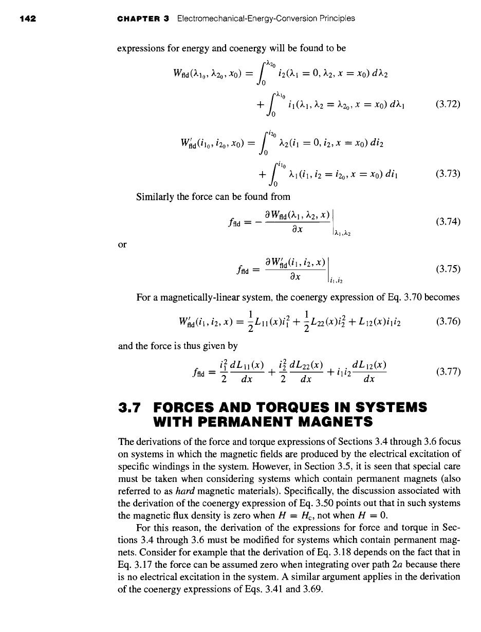
Figure 3.16 Plot of torque components for the multiply-excited system of Example 3.7.
notice that rotating the rotor by 180 ° from any given position gives the same air-gap reluctance
(hence the twice-angle variation). This torque component is known as the
reluctance torque.
The two torque components (mutual and reluctance), along with the total torque, are plotted
with MATLAB in Fig. 3.16.
)ractice Problem 3.
Find an expression for the torque of a symmetrical two-winding system whose inductances
vary as
Lll
-'-
L22 = 0.8 + 0.27 cos 40
L12 = 0.65 cos 20
for the condition that il = -i2 "- 0.37 A.
Solution
Tnd = --0.296 sin (40) + 0.178 sin (20)
The derivation presented above for angular displacement can be repeated in
an analogous fashion for the systems with linear displacement. If this is done, the
142 CHAPTER 3
ElectromechanicaI-Energy-Conversion Principles
expressions for energy and coenergy will be found to be
f
~-2 0
Wfld(/~.lo, ~'2o, XO) =
i2(~.1 = O, ~.2, x = Xo) d~.2
dO
f
~.l 0
-~- i1(~.1, ~.2 -- ~'2o, X = XO)d~.l
dO
(3.72)
or
f
l2
W~d(ilo,
i2o, Xo) = ~.2(il = O, i2, x = Xo)
di2
do
f
ll
+ ~.1(il, i2 = i2o,X
=xo) dil
dO
Similarly the force can be found from
O Wfld()~l, ~2, X)
ffld --
OX
~]
,)~2
(3.73)
ffld -"
(3.74)
O W~d(i l , i2, x)
8x
il,i2
(3.75)
For a magnetically-linear system, the coenergy expression of Eq. 3.70 becomes
1 1
W~d(il,iz, x) = -~Lll(X)i 2 + -~Lzz(x)i 2 + Llz(x)i,i2
and the force is thus given by
iZdLll(x)
fttd = "~ dx
(3.76)
i 2 dL22(x) dLl2(X)
I + i l i2 ~ (3.77)
2 dx dx
3.7
FORCES AND TORQUES IN SYSTEMS
WITH PERMANENT MAGNETS
The derivations of the force and torque expressions of Sections 3.4 through 3.6 focus
on systems in which the magnetic fields are produced by the electrical excitation of
specific windings in the system. However, in Section 3.5, it is seen that special care
must be taken when considering systems which contain permanent magnets (also
referred to as
hard
magnetic materials). Specifically, the discussion associated with
the derivation of the coenergy expression of Eq. 3.50 points out that in such systems
the magnetic flux density is zero when H = Hc, not when H = 0.
For this reason, the derivation of the expressions for force and torque in Sec-
tions 3.4 through 3.6 must be modified for systems which contain permanent mag-
nets. Consider for example that the derivation of Eq. 3.18 depends on the fact that in
Eq. 3.17 the force can be assumed zero when integrating over path 2a because there
is no electrical excitation in the system. A similar argument applies in the derivation
of the coenergy expressions of Eqs. 3.41 and 3.69.
3,7 Forces and Torques in Systems with Permanent Magnets 143
In systems with permanent magnets, these derivations must be carefully revisited.
In some cases, such systems have no windings at all, their magnetic fields are due
solely to the presence of permanent-magnet material, and it is not possible to base a
derivation purely upon winding fluxes and currents. In other cases, magnetic fields
may be produced by a combination of permanent magnets and windings.
A modification of the techniques presented in the previous sections can be used
in systems which contain permanent magnets. Although the derivation presented
here applies specifically to systems in which the magnet appears as an element of a
magnetic circuit with a uniform internal field, it can be generalized to more complex
situations; in the most general case, the field theory expressions for energy (Eq. 3.20)
and coenergy (Eq. 3.50) can be used.
The essence of this technique is to consider the system as having an additional
fictitious winding
acting upon the same portion of the magnetic circuit as does the
permanent magnet. Under normal operating conditions, the fictitious winding carries
zero current. Its function is simply that of a mathematical "crutch" which can be used
to accomplish the required analysis. The current in this winding can be adjusted to
zero-out the magnetic fields produced by the permanent magnet in order to achieve
the "zero-force" starting point for the analyses such as that leading from Eq. 3.17 to
Eq. 3.18.
For the purpose of calculating the energy and coenergy of the system, this winding
is treated as any other winding, with its own set of current and flux linkages. As a result,
energy and coenergy expressions can be obtained as a function of all the winding flux
linkages or currents, including those of the fictitious winding. Since under normal
operating conditions the current in this winding will be set equal to zero, it is useful
to derive the expression for the force from the system coenergy since the winding
currents are explicitly expressed in this representation.
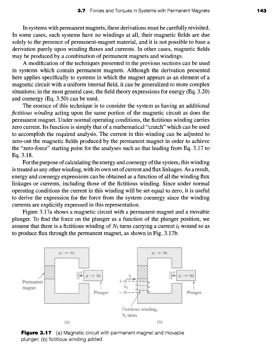
Figure 3.17a shows a magnetic circuit with a permanent magnet and a movable
plunger. To find the force on the plunger as a function of the plunger position, we
assume that there is a fictitious winding of Nf turns carrying a current if wound so as
to produce flux through the permanent magnet, as shown in Fig. 3.17b.
/
Permanent
magnet
1
ii!iii!iii!iii!ii•ii!!ii!iiii!ii•i•ii!•ii!ii•!iii!ii!iiiii•iii!ii•!iiiiii}i!••!•i•!!iii•ii•iii•}i•!}i•i!i!!i!•iii!i•i}••ii•!•!!ii••!•!•iii!•••i!••!!ii!•i••iii!•i•••ii }~iiiiii!i!iiiiiiiiiiiiiiiiiiiiiiiiiiiiiiiiiiii i er
~i~i~i~J:!~i~i~i~i~i~i~i~i~i:~iJ~:i~i~i~i:~.i~i~!~i~!~i~:!~:i~!~!~!~:!~:~i:~!~i~!~:!,~i~i~i~i~J~i~i~i~i:i:!~i~U
(a)
C~, i!ili~iiiiii!i!iiii!i!;!i!iiiiii!i!iiiiii~i!iiiiii!iiii!i~i!ii!iii~i
--
c Plunger
Fictitious winding,
Nf tums
(b)
Figure
3.17 (a) Magnetic circuit with permanent magnet and movable
plunger; (b) fictitious winding added.
144 CHAPTER 3
ElectromechanicaI-Energy-Conversion Principles
For this single-winding system we can write the expression for the differential
in coenergy from Eq. 3.37 as
dW~d(if, x) = ~.f dif + ffld dx
(3.78)
where the subscript 'f' indicates the fictitious winding. Corresponding to Eq. 3.40,
the force in this system can be written as
ffld = 0
W~d(if0x--
O, x) I if
(3.79)
where the partial derivative is taken while holding if constant, and the resultant expres-
sion is then evaluated at if = 0, which is equivalent to setting if--0 in the expression
for W~o before taking the derivative. As we have seen, holding if constant for the
derivative in Eq. 3.79 is a requirement of the energy method; it must be set to zero
to properly calculate the force due to the magnet alone so as not to include a force
component from current in the fictitious winding.
To calculate the coenergy W~d(if, x) in this system, it is necessary to integrate
Eq. 3.78. Since W~d is a state function of if and x, we are free to choose any integration
path we wish. Figure 3.18 illustrates a path over which this integration is particularly
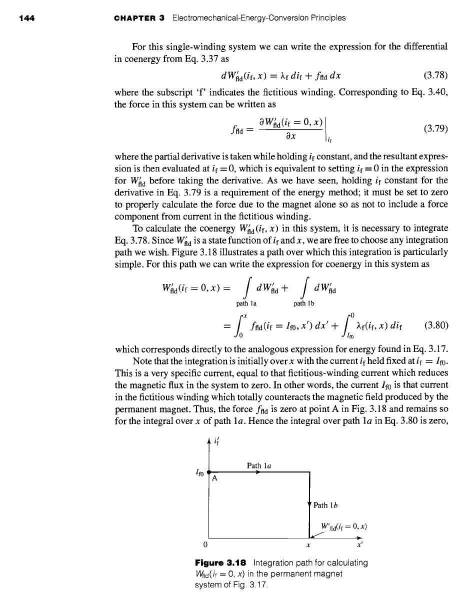
simple. For this path we can write the expression for coenergy in this system as
W~d(if -- O, x) = f dW~d+ / dW~d
path 1 a path 1 b
/0 x
-- ffld(if
= Ifo, X') dx' +
~,f(if,
x) dif
(3.80)
which corresponds directly to the analogous expression for energy found in Eq. 3.17.
Note that the integration is initially over x with the current
if
held fixed at
if ---- If0.
This is a very specific current, equal to that fictitious-winding current which reduces
the magnetic flux in the system to zero. In other words, the current If0 is that current
in the fictitious winding which totally counteracts the magnetic field produced by the
permanent magnet. Thus, the force
ffld
is zero at point A in Fig. 3.18 and remains so
for the integral over x of path la. Hence the integral over path la in Eq. 3.80 is zero,
Path la
Path 1 b
[
~W'fld (if = 0, X)
X X'
Figure
3.18 Integration path for calculating
Wild(if -- O, X)
in the permanent magnet
system of Fig. 3.17.
3.7
Forces and Torques in Systems with Permanent Magnets 145
and Eq. 3.80 reduces to
'
Whd(t f = 0, x) = ~.f(i~,
x)
di~
(3.81)
Note that Eq. 3.81 is perfectly general and does not require either the permanent
magnet or the magnetic material in the magnetic circuit to be linear. Once Eq. 3.81
has been evaluated, the force at a given plunger position x can be readily found from
Eq. 3.79. Note also that due to the presence of the permanent magnet, neither the
coenergy nor the force is zero when if is zero, as we would expect.
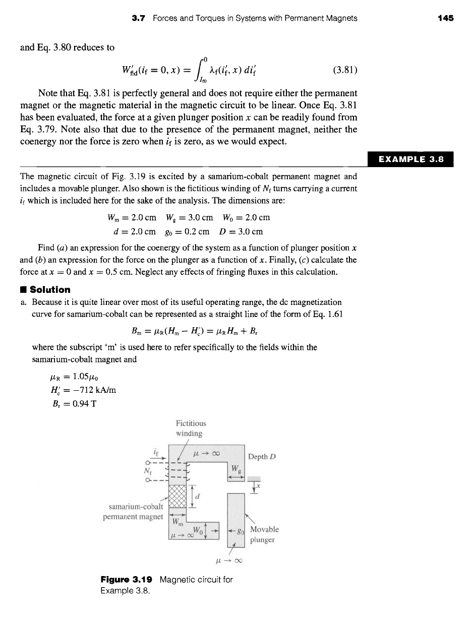
The magnetic circuit of Fig. 3.19 is excited by a samarium-cobalt permanent magnet and
includes a movable plunger. Also shown is the fictitious winding of Nf turns carrying a current
if which is included here for the sake of the analysis. The dimensions are:
Wm =
2.0 cm Wg = 3.0 cm W0 = 2.0 cm
d = 2.0 cm go = 0.2 cm D = 3.0 cm
Find (a) an expression for the coenergy of the system as a function of plunger position x
and (b) an expression for the force on the plunger as a function of x. Finally, (c) calculate the
force at x = 0 and x = 0.5 cm. Neglect any effects of fringing fluxes in this calculation.
II Solution
a. Because it is quite linear over most of its useful operating range, the dc magnetization
curve for samarium-cobalt can be represented as a straight line of the form of Eq. 1.61
B m = ttR(Hra- H~) = /L/,RH m -31-- Br
where the subscript 'm' is used here to refer specifically to the fields within the
samarium-cobalt magnet and
/ZR = 1.05/Z0
H e' = --712 kA/m
Br =0.94 T
/re
o-
samarium-col
permanent mag
Fictitious
winding
Depth D
\
Movable
I~S plunger
/
/z ----> oo
Figure
3.19 Magnetic circuit for
Example 3.8.