Fitzgerald A.E. Electric Machinery
Подождите немного. Документ загружается.

146 CHAPTER 3 ElectromechanicaI-Energy-Conversion Principles
Note from Fig. 1.19 that the DC magnetization curve for samarium-cobalt is not
completely linear; it bends slightly downward for low flux densities. Hence, in the
linearized
B-H
characteristic given above, the apparent coercivity H c' is somewhat larger
than the actual coercivity of samarium-cobalt.
From Eq. 1.5 we can write
Nfif =
Hind + Hgx + Hogo
where the subscript 'g' refers to the variable gap and the subscript '0' refers to the fixed
gap. Similarly from the continuity of flux condition, Eq. 1.3, we can write
BmWmD-- BgWgD = BoWoD
Recognizing that in the air gaps
Bg --/zoHg
and Bo
=/~oHo,
we can solve the above
equations for Bm:
Bm "--
~R(Nf/f-
H~d)
d+ + ,0
Finally we can solve for the flux linkages/~,f of the fictitious winding as
)~f = Nf W m D Bm =
NfWmD#R(Nfif- H~d)
x go
UR +W0)
d+Wm(.0)(V
Thus we see that the flux linkages
~f
will be zero when
if "-- Ifo --
Hcd/Nf =
-Brd/(#RNf)
and from Eq. 3.81 we can find the coenergy as
[ NfWmO#R(Nfi f - H~d)]
Wild(X)
-- d/Nf Ld T
Wm(~u~ooS-(-~ ~ ~w~o ~
dif
WmD(Brd) 2
2/ZR[d-~-Wm(~R)(~g'g "~- g0)]"0 W0
Note that the answer does not depend upon Nf or if which is as we would expect
since the fictitious winding does not actually exist in this system.
b. Once the coenergy has been found, the force can be found from Eq. 3.79 as
ffld ~" --
W2mD(Brd) 2
2#°Wg[d+Wm(UR)(~+ g°)] Wo
Notice that the force is negative, indicating that the force is acting in the direction to
decrease x, that is to pull the plunger in the direction which decreases the gap.
c. Finally, substitution into the force expression yields
-l15N atx =0cm
f,d= -85.8N atx=0.5cm
3.7 Forces and Torques in Systems with Permanent Magnets 147
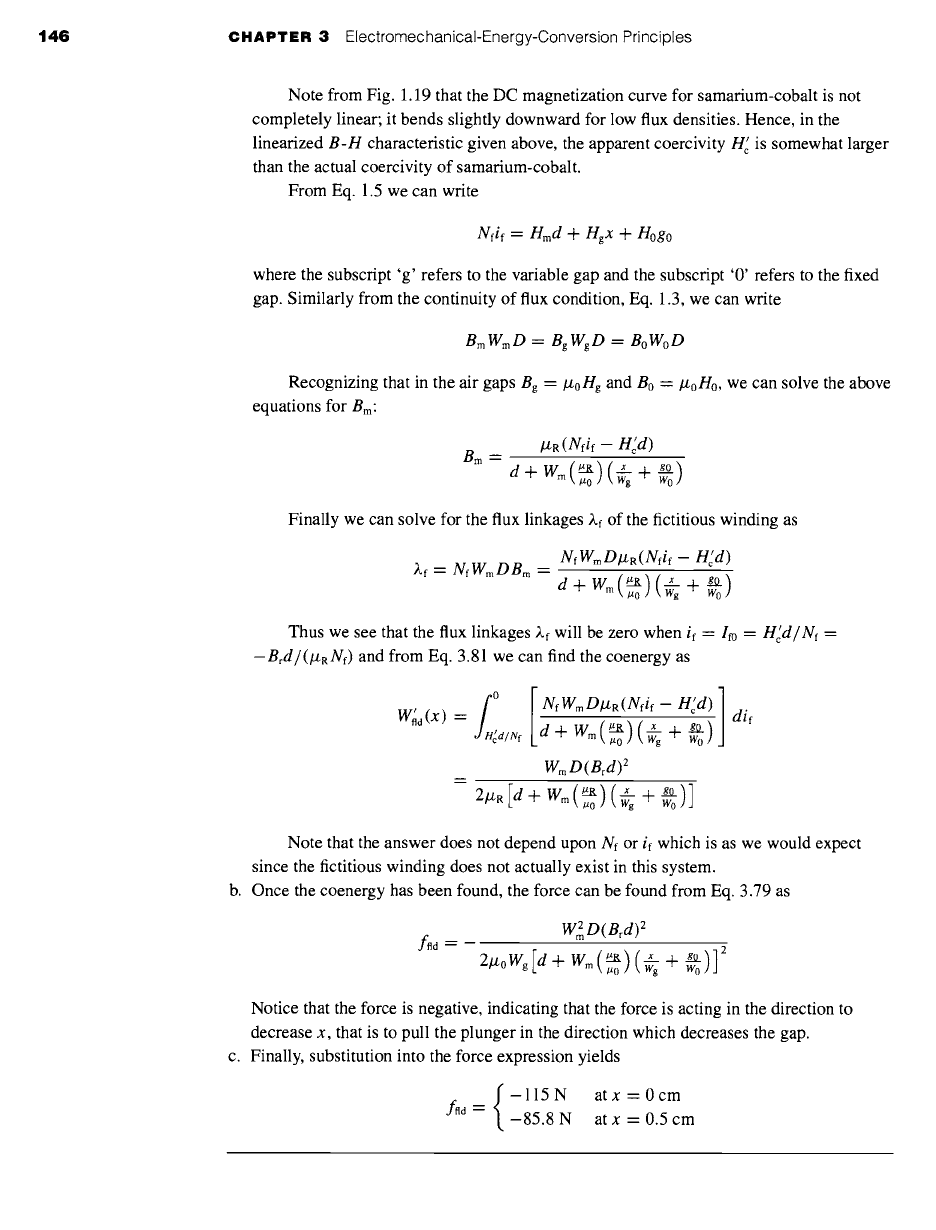
(a) Derive an expression for the coenergy in the magnetic circuit of Fig. 3.20 as a function of
the plunger position x. (b) Derive an expression for the x-directed force on the plunger and
evaluate it at x =
Wg/2.
Neglect any effects of fringing fluxes. The dimensions are:
Wm=2.0cm Wg=2.5cm D=3.0cm
d= 1.0cm g0=0.2cm
Solution
iii!ii!iiiiiiiii!iii!iiiiiiiiiiiiiiiiiiiiiiiiiiiiii ~iii '~iJii~iiii'~iiiiiiii~iiii!iiiiiii
~:~i~i~'~'~iii~i ~i ~J~ii~! ~!i~i~i,i ........
[~i~i~i~ii~jPi~ii~iii~:ii~iii2ii~ii2!ii!j~iF~iy~iii~:~iii!ii~ii~ii~:~ii!ii~!ii!i!~iii~iii~i~i~ Depth D
~~ x~~
samafium-cobalt~
magnet iiiiiiiii!iiiiiii!~iiiiii!i!iliiiiiiiiii! .....................................................................
iiii!!ii~iiiii~i~iii!ii~ii~iii!ii~i~iii~iiiiiiiiii!iiii~i~i~i~iiiiiiiiiiJ!iiiiii!!~ii~ii~iiii~iiiiiii~iiiiiiiii~iiiiiii~!i~i!iiiiii
Figure 3.20
Magnetic circuit for Practice
Problem 3.8.
WmD(Brd) 2
(Wg-x)
Ad ~ --
2 2
gW~DB r
~R (Wg-x) / ]
lzo(Wg - x)2 [l + (lzo ) ( wgwm "~ 2
Atx =
Wg/2,
fnd = --107 N.
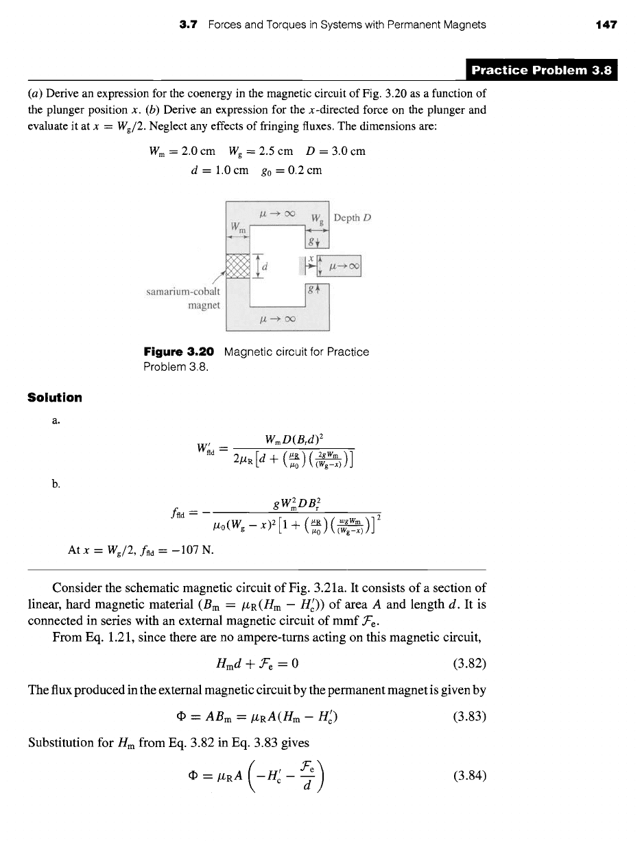
Consider the schematic magnetic circuit of Fig. 3.21 a. It consists of a section of
linear, hard magnetic material (Bm = krR(Hm -- Hc~)) of area A and length d. It is
connected in series with an external magnetic circuit of mmf f'e.
From Eq. 1.21, since there are no ampere-turns acting on this magnetic circuit,
Hmd
4- Ore = 0 (3.82)
The flux produced in the external magnetic circuit by the permanent magnet is given by
d~ = ABm
=/ZRA(Hm- Hc ~)
Substitution for Hm from Eq. 3.82 in Eq. 3.83 gives
~ =/ZRA (-Hcr - -~)
(3.83)
(3.84)
148 CHAPTER 3 ElectromechanicaI-Energy-Conversion Principles
Are
>
3_ +
Linear, hard
magnetic material
B m =/ZR(H m -1-
Hc')
(a)
Area A
(N/)equiv~~ d ~"- I ~~ii
Linear magnetic
material B --/ZRH
(b)
Figure
3.21 (a) Generic magnetic circuit containing a section of linear,
permanent-magnet material. (b) Generic magnetic circuit in which the
permanent-magnet material has been replaced by a section of linear
magnetic material and a fictitious winding.
Now consider the schematic magnetic circuit of Fig. 3.21b in which the lin-
ear, hard magnetic material of Fig. 3.21a has been replaced by soft, linear mag-
netic material of the same permeability (B = #RH) and of the same dimensions,
length d and area A. In addition, a winding carrying (Ni)equiv ampere-turns has been
included.
For this magnetic circuit, the flux can be shown to be given by
dp = iX R A ( ( N i ) equiv
.~'e )
d d (3.85)
Comparing Eqs. 3.84 and 3.85, we see that the same flux is produced in the external
magnetic circuit if the ampere-turns, (Ni)equiv, in the winding of Fig. 3.21b is equal
to
-ncd.
This is a useful result for analyzing magnetic-circuit structures which contain
linear, permanent-magnet materials whose
B-H
characteristic can be represented in
the form of Eq. 1.61. In such cases, replacing the permanent-magnet section with a
section of linear-magnetic material of the same permeability #R and geometry and
an equivalent winding of ampere-tums
(gi)equiv
--
-ncd
(3.86)
results in the same flux in the external magnetic circuit. As a result, both the lin-
ear permanent magnet and the combination of the linear magnetic material and the
winding are indistinguishable with regard to the production of magnetic fields in the
external magnetic circuit, and hence they produce identical forces. Thus, the analysis
of such systems may be simplified by this subsitution, as is shown in Example 3.9.
This technique is especially useful in the analysis of magnetic circuits containing both
a permanet magnetic and one or more windings.
EXAMPLE 3.9
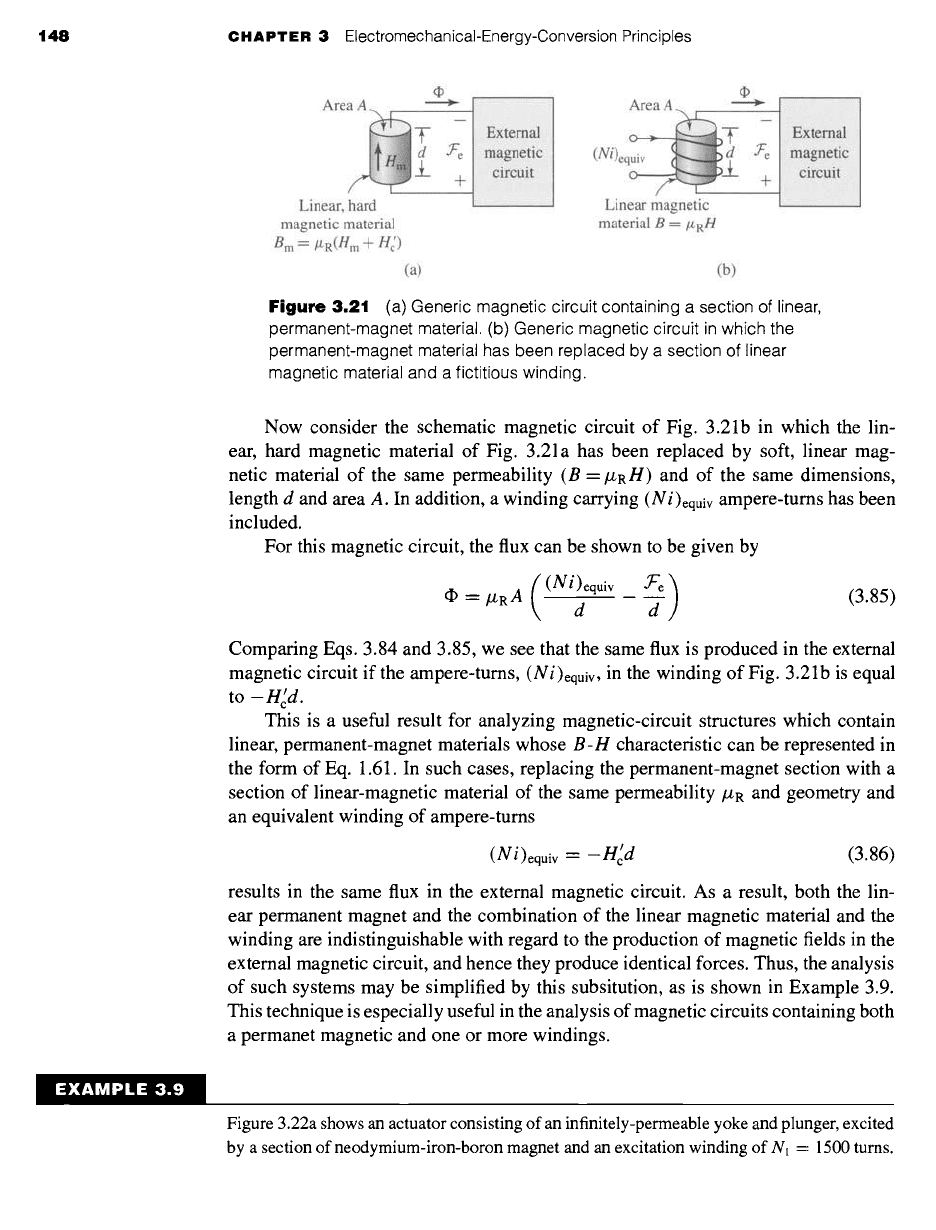
Figure 3.22a shows an actuator consisting of an infinitely-permeable yoke and plunger, excited
by a section of neodymium-iron-boron magnet and an excitation winding of Nl = 1500 turns.
3.7 Forces and Torques in Systems with Permanent Magnets 149
neodymium-iron-boron K
magnet
tu ns
Depth D
I
# ............................................................................................ unger
!!i!ii!iii!iiN.
(a)
+
(Ni)equiv (
+
Nlil (
)
0
(b)
R x
Rg o
Rm
Figure
3.22 (a) Actuator for Example 3.9. (b) Equivalent circuit for the actuator
with the permanent magnet replaced by linear material and an equivalent
winding carrying (Ni)equiv ampere-turns.
The dimensions are:
W=4.0cm Wl=4.5cm D=3.5cm
d=8mm g0=lmm
Find (a) the x-directed force on the plunger when the current in the excitation winding is
zero and x = 3 mm. (b) Calculate the current in the excitation winding required to reduce the
plunger force to zero.
II Solution
a. As discussed in Section 1.6, the dc-magnetization characteristic of neodymium-iron-
boron can be represented by a linear relationship of the form
B =/~R(H -- Hc r) = Br + ~RH
where/z R =
1.06/z0, H e' = -940 kA/m and Br = 1.25 T. As discussed in this section, we
can replace the magnet by a section of linear material of permeability/ZR and an
equivalent winding of ampere-turns
(Ni)equiv =-H~d
=-(-9.4 x 10⁵)(8
x 10 -3) --7520
ampere-turns
Based upon this substitution, the equivalent circuit for the system becomes that of
Fig. 3.22b. There are two sources of mmf in series with three reluctances: the variable
gap Rx, the fixed gap ~0, and the magnet Am.
'T~, x
~0
'~m --
Izo W~ D
go
lzo W D
d
lzR WD
150
CHAPTER 3 ElectromechanicaI-Energy-Conversion Principles
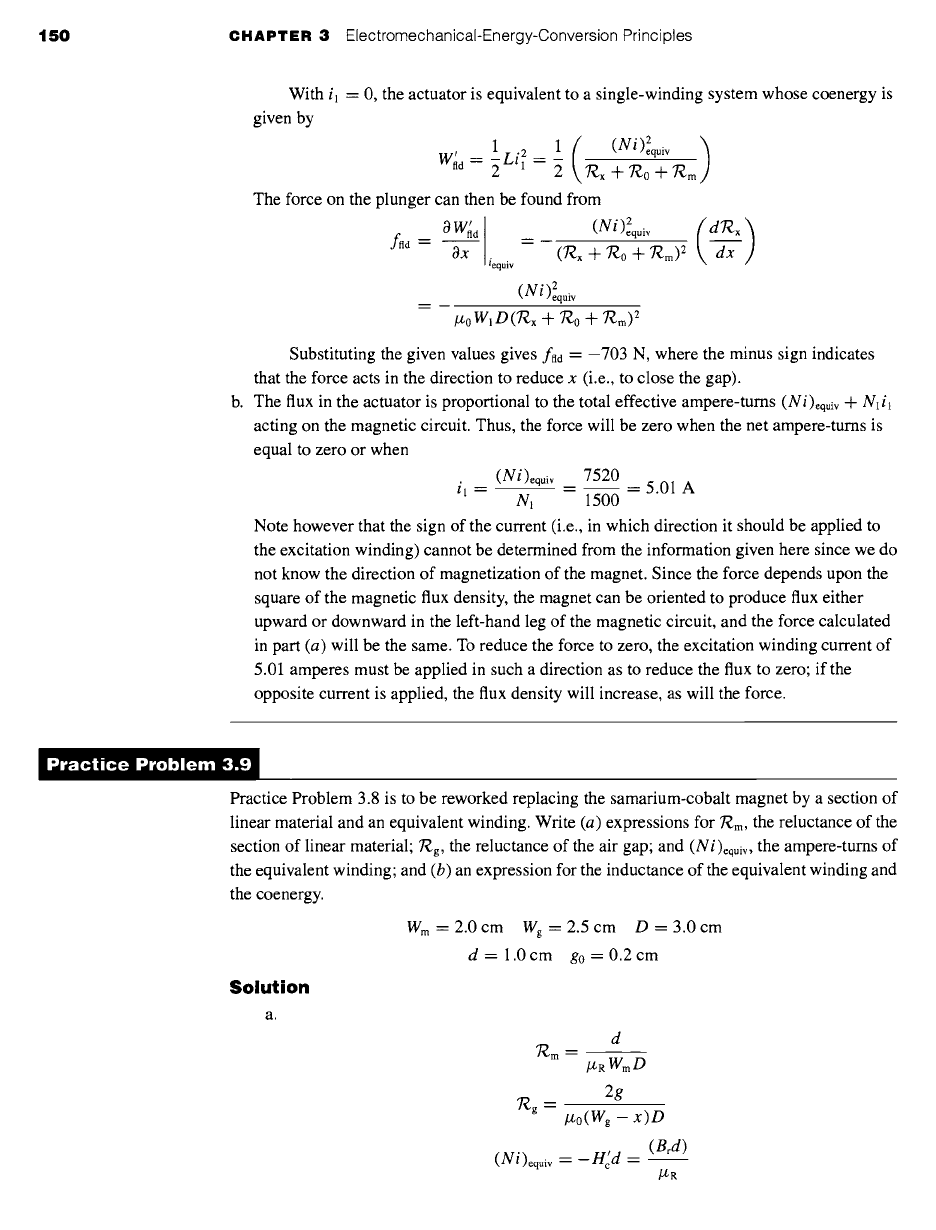
With
il = 0,
the actuator is equivalent to a single-winding system whose coenergy is
given by
( equiv )
1Li" 1 = 1 (Ni 2
Wild-" 2 2 nx --~- 7"~0 --]- 7"~m
The force on the plunger can then be found from
0 Wild
__
(Ni)eequiv
( dRx )
f"~ = T~ - -(TZx + 7Zo + 7Zm) ~ \
iequiv
• 2
( N t ) equiv
/z0Wl D(Te,,x + ~0 +
7"~'m) 2
Substituting the given values gives fnd = -703 N, where the minus sign indicates
that the force acts in the direction to reduce x (i.e., to close the gap).
b. The flux in the actuator is proportional to the total effective ampere-turns (Ni)equiv + N1 i l
acting on the magnetic circuit. Thus, the force will be zero when the net ampere-turns is
equal to zero or when
(Ni)equiv 7520
il = -- -- 5.01 A
Nl 1500
Note however that the sign of the current (i.e., in which direction it should be applied to
the excitation winding) cannot be determined from the information given here since we do
not know the direction of magnetization of the magnet. Since the force depends upon the
square of the magnetic flux density, the magnet can be oriented to produce flux either
upward or downward in the left-hand leg of the magnetic circuit, and the force calculated
in part (a) will be the same. To reduce the force to zero, the excitation winding current of
5.01 amperes must be applied in such a direction as to reduce the flux to zero; if the
opposite current is applied, the flux density will increase, as will the force.
D t
ractice Problem 3.,
Practice Problem 3.8 is to be reworked replacing the samarium-cobalt magnet by a section of
linear material and an equivalent winding. Write (a) expressions for 7"¢-m, the reluctance of the
section of linear material; 7?,.g, the reluctance of the air gap; and (Ni)equiv, the ampere-turns of
the equivalent winding; and (b) an expression for the inductance of the equivalent winding and
the coenergy.
Solution
Wm=2.0cm Wg=2.5cm D=3.0cm
d= 1.0cm g0=0.2cm
7~m
#RWmD
2g
n
'/'~g -- #0(Wg --
x)D
(Ni)equiv :
-H'd =
(Brd)
/ZR
3.8 Dynamic Equations 151
Wild m
Z
N 2
equiv
(~m -3 I- T~g)
Li{quiv (Brd) 2
WmD(Brd) 2
2 2# 2
(7"~ m -3 I- "~.g)
2]J~R [d --~- (/zo ) ( 2~gWm
(Wg-x)
Clearly the methods described in this chapter can be extended to handle situations
in which there are permanent magnets and multiple current-carrying windings. In
many devices of practical interest, the geometry is sufficiently complex, independent
of the number of windings and/or permanent magnets, that magnetic-circuit analysis is
not necessarily applicable, and analytical solutions can be expected to be inaccurate, if
they can be found at all. In these cases, numerical techniques, such as the finite-element
method discussed previously, can be employed. Using this method, the coenergy of
Eq. 3.48, or Eq. 3.50 if permanet magnets are involved, can be evaluated numerically
at constant winding currents and for varying values of displacement.
3.8 DYNAMIC EQUATIONS
We have derived expressions for the forces and torques produced in electromechanical-
energy-conversion devices as functions of electrical terminal variables and mechani-
cal displacement. These expressions were derived for conservative energy-conversion
systems for which it can be assumed that losses can be assigned to external electrical
and mechanical elements connected to the terminals of the energy-conversion system.
Such energy-conversion devices are intended to operate as a coupling means between
electric and mechanical systems. Hence, we are ultimately interested in the operation
of the complete electromechanical system and not just of the electromechanical-
energy-conversion system around which it is built.
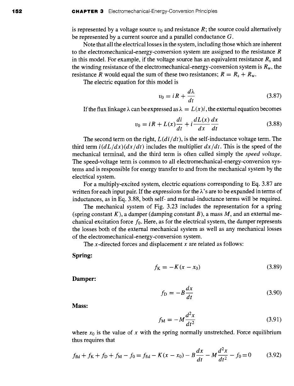
The model of a simple electromechancal system shown in Fig. 3.23 shows the ba-
sic system components, the details of which may vary from system to system. The sys-
tem shown consists of three parts: an external electric system, the electromechanical-
energy-conversion system, and an external mechanical system. The electric system
+ R
ffld
v
K
0
£
Figure 3.23 Model of a
singly-excited electromechanical system.
152 CHAPTER 3 ElectromechanicaI-Energy-Conversion Principles
is represented by a voltage source v0 and resistance R; the source could alternatively
be represented by a current source and a parallel conductance G.
Note that all the electrical losses in the system, including those which are inherent
to the electromechanical-energy-conversion system are assigned to the resistance R
in this model. For example, if the voltage source has an equivalent resistance Rs and
the winding resistance of the electromechanical-energy-conversion system is Rw, the
resistance R would equal the sum of these two resistances; R = Rs + Rw.
The electric equation for this model is
d)~
v0 = i R + (3.87)
dt
If the flux linkage ~. can be expressed as ~. = L (x)i, the external equation becomes
di dL(x) dx
vo = i R + L(x)-~ + i dx dt
(3.88)
The second term on the fight,
L(di/dt),
is the self-inductance voltage term. The
third term
i(dL/dx)(dx/dt)
includes the multiplier
dx/dt.
This is the speed of the
mechanical terminal, and the third term is often called simply the
speed voltage.
The speed-voltage term is common to all electromechanical-energy-conversion sys-
tems and is responsible for energy transfer to and from the mechanical system by the
electrical system.
For a multiply-excited system, electric equations corresponding to Eq. 3.87 are
written for each input pair. If the expressions for the )~'s are to be expanded in terms of
inductances, as in Eq. 3.88, both self- and mutual-inductance terms will be required.
The mechanical system of Fig. 3.23 includes the representation for a spring
(spring constant K), a damper (damping constant B), a mass M, and an external me-
chanical excitation force f0. Here, as for the electrical system, the damper represents
the losses both of the external mechanical system as well as any mechanical losses
of the electromechanical-energy-conversion system.
The x-directed forces and displacement x are related as follows:
Spring:
Damper:
Mass:
fK = -- K (x - Xo) (3.89)
dx
fD = -B-- (3.90)
dt
d2x
fM = -M dt-- ~
(3.91)
where x0 is the value of x with the spring normally unstretched. Force equilibrium
thus requires that
f.,~ + fK + fD + fM -- f0 = f.,~ -- K (x - xo) - B-- -
dx d2x
M - fo = 0 (3.92)
dt
3.8
Dynamic Equations 153
Combining Eqs. 3.88 and 3.92, the differential equations for the overall system
of Fig. 3.23 for arbitrary inputs
vo(t)
and
fo(t) are
thus
di dL(x)
vo(t) = i R + L(x)--~ + i dx
(3.93)
d2x dx
fo(t) = -M--r~at ~ - B d----t - K(x - xo) + ffld(X, i)
(3.94)
The functions L (x) and
ffld (X,
i) depend on the properties of the electromechanical-
energy-conversion system and are calculated as previously discussed.
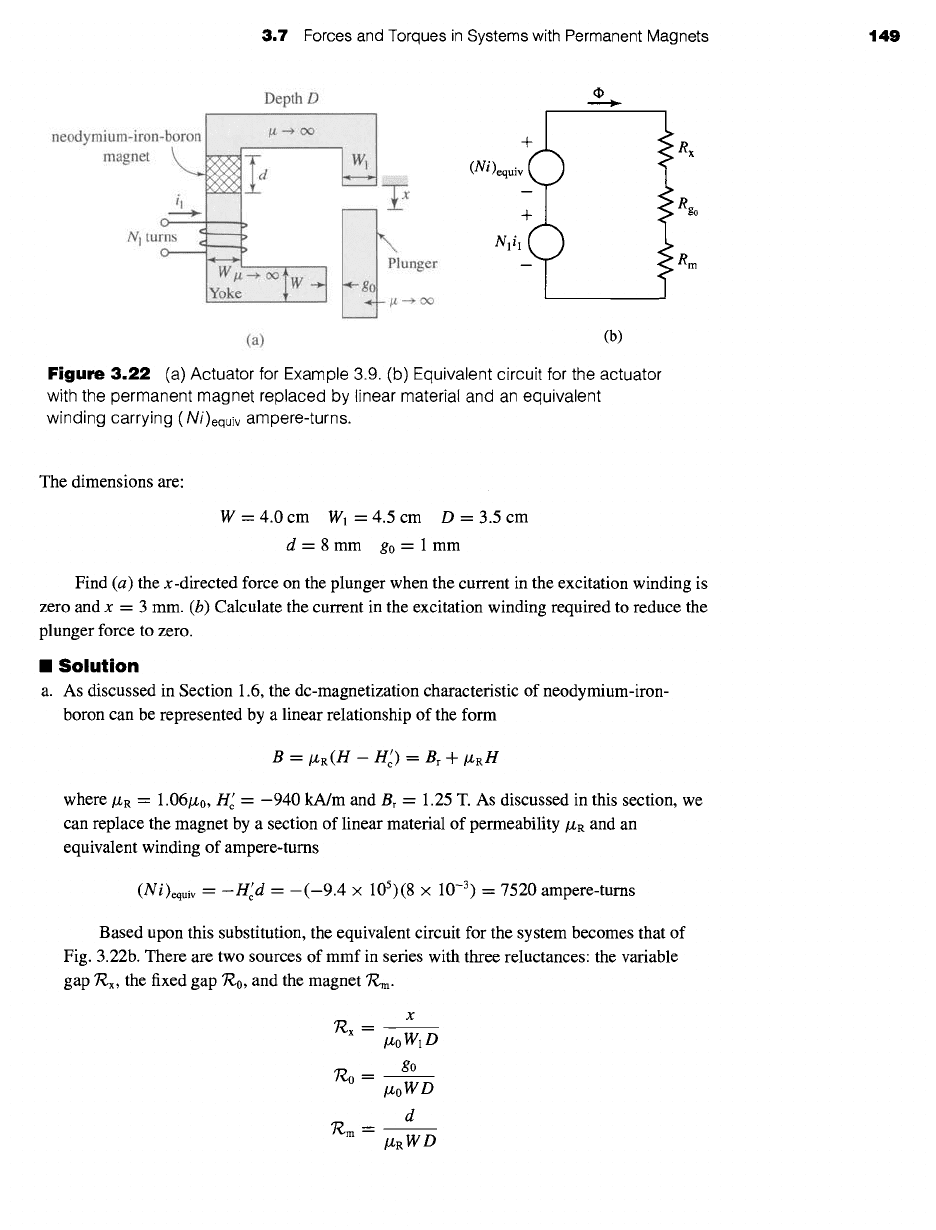
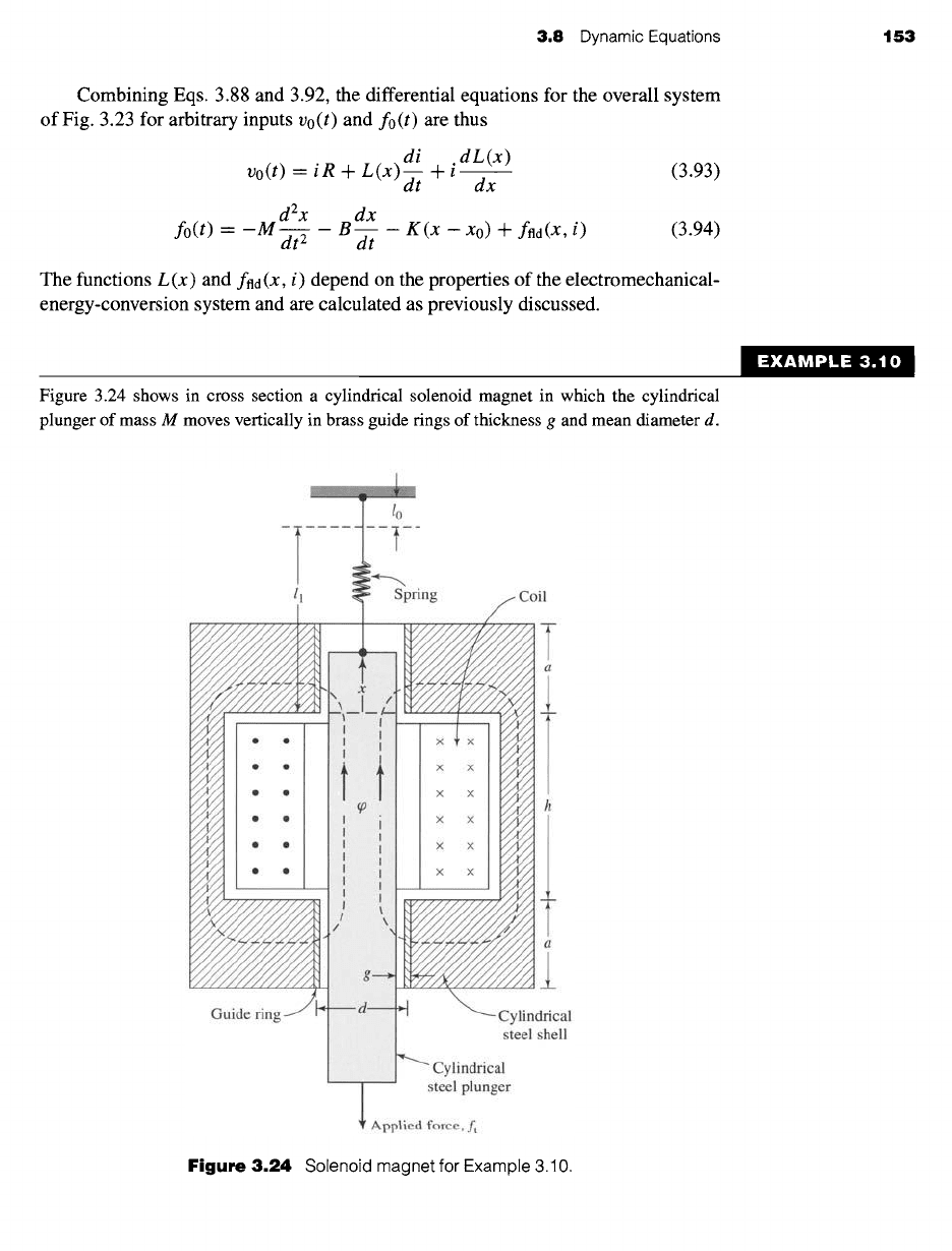
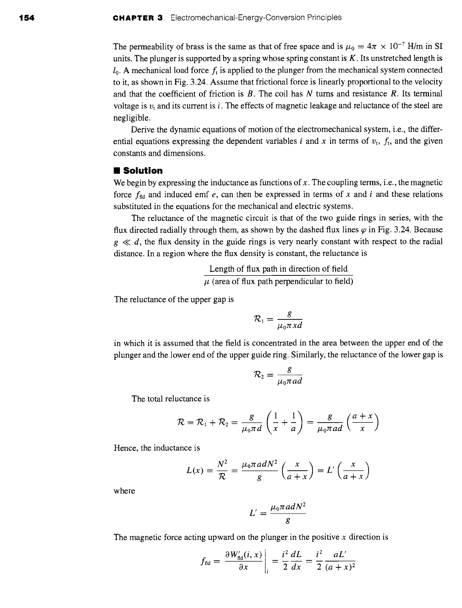
Figure 3.24 shows in cross section a cylindrical solenoid magnet in which the cylindrical
plunger of mass M moves vertically in brass guide rings of thickness g and mean diameter d.
EXAMPLE 3.10
Guide fin
--T ....
ll
I
pring
X X
Coil
/
--- Cylindrical
steel shell
iiiiiiiiiiiiiiiiiiii!iiiiiiiiiiiiiiiii!i]iii!
~ Cylindrical
steel plunger
Applied force, ft
Figure
3.24 Solenoid magnet for Example 3.10.
154 CHAPTER 3
ElectromechanicaI-Energy-Conversion Principles
The permeability of brass is the same as that of free space and is #0 = 47r x 10 -7 H/m in SI
units. The plunger is supported by a spring whose spring constant is K. Its unstretched length is
10. A mechanical load force ft is applied to the plunger from the mechanical system connected
to it, as shown in Fig. 3.24. Assume that frictional force is linearly proportional to the velocity
and that the coefficient of friction is B. The coil has N turns and resistance R. Its terminal
voltage is vt and its current is i. The effects of magnetic leakage and reluctance of the steel are
negligible.
Derive the dynamic equations of motion of the electromechanical system, i.e., the differ-
ential equations expressing the dependent variables i and x in terms of vt, ft, and the given
constants and dimensions.
II
Solution
We begin by expressing the inductance as functions of x. The coupling terms, i.e., the magnetic
force fad and induced emf e, can then be expressed in terms of x and i and these relations
substituted in the equations for the mechanical and electric systems.
The reluctance of the magnetic circuit is that of the two guide rings in series, with the
flux directed radially through them, as shown by the dashed flux lines q9 in Fig. 3.24. Because
g << d, the flux density in the guide rings is very nearly constant with respect to the radial
distance. In a region where the flux density is constant, the reluctance is
Length of flux path in direction of field
# (area of flux path perpendicular to field)
The reluctance of the upper gap is
g
7"~l-
lZozr xd
in which it is assumed that the field is concentrated in the area between the upper end of the
plunger and the lower end of the upper guide ring. Similarly, the reluctance of the lower gap is
7"~2 =
g
lzorr ad
The total reluctance is
Hence, the inductance is
where
N 2
L(x) - =
T¢
+ 1)_. (a+x)
lzozr d x a #oread x
g a+x a+x
L
/ ___
#o:rr ad N 2
The magnetic force acting upward on the plunger in the positive x direction is
Ad "-"
0W~d(i, X) I
= i2
dL i 2 aL'
a-----7--
i ~ ~ = ~
(a ¥-~)~
3.9
Analytical Techniques 155
The induced emf in the coil is
or
d di dL dx
e= t- ~(Li) = L + i
dx dt
e=L'( x ) di L'( ai ) dx
a+x d-t + (a+x) 2
dt
Substitution of the magnetic force in the differential equation of motion of the mechanical
l_L, ai 2
dx K (x - lo) +
dt 2 (a
Jl-
X) 2
system (Eq. 3.94) gives
d2x
ft = -M--d- ~
The voltage equation for the electric system is (from Eq. 3.93)
vt=iR+L,( x )di ( a ) dx
a + x ~ + i L' (a + x)
2
dt
These last two equations are the desired results. They are valid only as long as the upper
end of the plunger is well within the upper guide ring, say, between the limits 0.1 a < x < 0.9a.
This is the normal working range of the solenoid.
3.9 ANALYTICAL TECHNIQUES
We have described relatively simple devices in this chapter. The devices have one or
two electrical terminals and one mechanical terminal, which is usually constrained to
incremental motion. More complicated devices capable of continuous energy conver-
sion are treated in the following chapters. The analytical techniques discussed here
apply to the simple devices, but the principles are applicable to the more complicated
devices as well.
Some of the devices described in this chapter are used to produce gross motion,
such as in relays and solenoids, where the devices operate under essentially "on"
and "off" conditions. Analysis of these devices is carried out to determine force as a
function of displacement and reaction on the electric source. Such calculations have
already been made in this chapter. If the details of the motion are required, such as the
displacement as a function of time after the device is energized, nonlinear differential
equations of the form of Eqs. 3.93 and 3.94 must be solved.
In contrast to gross-motion devices, other devices such as loudspeakers, pickups,
and transducers of various kinds are intended to operate with relatively small displace-
ments and to produce a linear relationship between electrical signals and mechanical
motion, and vice versa. The relationship between the electrical and mechanical vari-
ables is made linear either by the design of the device or by restricting the excursion
of the signals to a linear range. In either case the differential equations are linear and
can be solved using standard techniques for transient response, frequency response,
and so forth, as required.