Fitzgerald A.E. Electric Machinery
Подождите немного. Документ загружается.

106 CHAPTER 2 Transformers
2.11 The resistances and leakage reactances of a 30-kVA, 60-Hz, 2400-V:240-V
distribution transformer are
R1 = 0.68 f2
R2 =
0.0068 f2
Xll = 7.8 f2
X12 =
0.0780
where subscript 1 denotes the 2400-V winding and subscript 2 denotes the
240-V winding. Each quantity is referred to its own side of the transformer.
a. Draw the equivalent circuit referred to (i) the high- and
(ii)
the
low-voltage sides. Label the impedances numerically.
b. Consider the transformer to deliver its rated kVA to a load on the
low-voltage side with 230 V across the load. (i) Find the high-side
terminal voltage for a load power factor of 0.85 power factor lagging.
(ii)
Find the high-side terminal voltage for a load power factor of 0.85
power factor leading.
c. Consider a rated-kVA load connected at the low-voltage terminals
operating at 240V. Use MATLAB to plot the high-side terminal voltage as
a function of the power-factor angle as the load power factor varies from
0.6 leading through unity power factor to 0.6 pf lagging.
2.12 Repeat Problem 2.11 for a 75-kVA, 60-Hz, 4600-V:240-V distribution
transformer whose resistances and leakage reactances are
R1 = 0.846 f2 R2 = 0.00261
X~ = 26.8 f2 X12 = 0.0745 f2
where subscript 1 denotes the 4600-V winding and subscript 2 denotes the
240-V winding. Each quantity is referred to its own side of the transformer.
2.13 A single-phase load is supplied through a 35-kV feeder whose impedance is
95 + j360 f2 and a 35-kV:2400-V transformer whose equivalent impedance is
0.23 + j 1.27 f2 referred to its low-voltage side. The load is 160 kW at 0.89
leading power factor and 2340 V.
a. Compute the voltage at the high-voltage terminals of the transformer.
b. Compute the voltage at the sending end of the feeder.
c. Compute the power and reactive power input at the sending end of the
feeder.
2.14 Repeat Example 2.6 with the transformer operating at full load and unity
power factor.
2.15 The nameplate on a 50-MVA, 60-Hz single-phase transformer indicates that it
has a voltage rating of 8.0-kV:78-kV. An open-circuit test is conducted from
the low-voltage side, and the corresponding instrument readings are 8.0 kV,
62.1 A, and 206 kW. Similarly, a short-circuit test from the low-voltage side
gives readings of 674 V, 6.25 kA, and 187 kW.
a. Calculate the equivalent series impedance, resistance, and reactance of the
transformer as referred to the low-voltage terminals.
2.11 Problems 107
b. Calculate the equivalent series impedance of the transformer as referred to
the high-voltage terminals.
c. Making appropriate approximations, draw a T equivalent circuit for the
transformer.
d. Determine the efficiency and voltage regulation if the transformer is
operating at the rated voltage and load (unity power factor).
e. Repeat part (d), assuming the load to be at 0.9 power factor leading.
2.16 A 550-kVA, 60-Hz transformer with a 13.8-kV primary winding draws 4.93 A
and 3420 W at no load, rated voltage and frequency. Another transformer has
a core with all its linear dimensions ~ times as large as the corresponding
dimensions of the first transformer. The core material and lamination
thickness are the same in both transformers. If the primary windings of both
transformers have the same number of turns, what no-load current and power
will the second transformer draw with 27.6 kV at 60 Hz impressed on its
primary?
2.17 The following data were obtained for a 20-kVA, 60-Hz, 2400:240-V
distribution transformer tested at 60 Hz:
t i ,i
Voltage, Current, Power,
V A W
With high-voltage winding open-circuited 240
With low-voltage terminals short-circuited 61.3
1.038 122
8.33 257
a. Compute the efficiency at full-load current and the rated terminal voltage
at 0.8 power factor.
b. Assume that the load power factor is varied while the load current and
secondary terminal voltage are held constant. Use a phasor diagram to
determine the load power factor for which the regulation is greatest. What
is this regulation?
2.18 A 75-kVa, 240-V:7970-V, 60-Hz single-phase distribution transformer has the
following parameters referred to the high-voltage side:
R1 = 5.93 f2 X1
=
43.2
R2 =
3.39 f2
X2 =
40.6 f2
Rc = 244 kf2
X m =
114 k~
Assume that the transformer is supplying its rated kVA at its low-voltage
terminals. Write a MATLAB script to determine the efficiency and regulation
of the transformer for any specified load power factor (leading or lagging).
You may use reasonable engineering approximations to simplify your
analysis. Use your MATLAB script to determine the efficiency and regulation
for a load power factor of 0.87 leading.
2.19 The transformer of Problem 2.11 is to be connected as an autotransformer.
Determine (a) the voltage ratings of the high- and low-voltage windings for
this connection and (b) the kVA rating of the autotransformer connection.
108 CHAPTER 2 Transformers
2.20 A 120:480-V, 10-kVA transformer is to be used as an autotransformer to
supply a 480-V circuit from a 600-V source. When it is tested as a
two-winding transformer at rated load, unity power factor, its efficiency
is 0.979.
a. Make a diagram of connections as an autotransformer.
b. Determine its kVA rating as an autotransformer.
c. Find its efficiency as an autotransformer at full load, with 0.85 power
factor lagging.
2.21 Consider the 8-kV:78-kV, 50-MVA transformer of Problem 2.15 connected as
an autotransformer.
a. Determine the voltage ratings of the high- and low-voltage windings for
this connection and the kVA rating of the autotransformer connection.
b. Calculate the efficiency of the transformer in this connection when it is
supplying its rated load at unity power factor.
2.22 Write a MATLAB script whose inputs are the rating (voltage and kVA) and
rated-load, unity-power-factor efficiency of a single-transformer and whose
output is the transformer rating and rated-load, unity-power-factor efficiency
when connected as an autotransformer.
2.23 The high-voltage terminals of a three-phase bank of three single-phase
transformers are supplied from a three-wire, three-phase 13.8-kV (line-to-line)
system. The low-voltage terminals are to be connected to a three-wire,
three-phase substation load drawing up to 4500 kVA at 2300 V line-to-line.
Specify the required voltage, current, and kVA ratings of each transformer
(both high- and low-voltage windings) for the following connections:
High-voltage Low-voltage
Windings Windings
a. Y A
b. A Y
c. Y Y
d. A A
2.24 Three 100-MVA single-phase transformers, rated at 13.8 kV:66.4 kV, are to be
connected in a three-phase bank. Each transformer has a series impedance of
0.0045 + j0.19 f2 referred to its 13.8-kV winding.
a. If the transformers are connected Y-Y, calculate (i) the voltage and power
rating of the three-phase connection,
(ii)
the equivalent impedance as
referred to its low-voltage terminals, and
(iii)
the equivalent impedance as
referred to its high-voltage terminals.
b. Repeat part (a) if the transformer is connected Y on its low-voltage side
and A on its high-voltage side.
2.25 Repeat Example 2.8 for a load drawing rated current from the transformers at
unity power factor.
2.11 Problems 109
2.26 A three-phase Y-A transformer is rated 225-kV:24-kV, 400 MVA and has a
series reactance of 11.7 f2 as referred to its high-voltage terminals. The
transformer is supplying a load of 325 MVA, with 0.93 power factor lagging
at a voltage of 24 kV (line-to-line) on its low-voltage side. It is supplied from
a feeder whose impedance is 0.11 + j 2.2 f2 connected to its high-voltage
terminals. For these conditions, calculate (a) the line-to-line voltage at the
high-voltage terminals of the transformer and (b) the line-to-line voltage at the
sending end of the feeder.
2.27 Assume the total load in the system of Problem 2.26 to remain constant at
325 MVA. Write a MATLAB script to plot the line-to-line voltage which must
be applied to the sending end of the feeder to maintain the load voltage at
24 kV line-to-line for load power factors in range from 0.75 lagging to unity
to 0.75 leading. Plot the sending-end voltage as a function of power factor
angle.
2.28 A A-Y-connected bank of three identical 100-kVA, 2400-V: 120-V, 60-Hz
transformers is supplied with power through a feeder whose impedance is
0.065 + j0.87 f2 per phase. The voltage at the sending end of the feeder is held
constant at 2400 V line-to-line. The results of a single-phase short-circuit test
on one of the transformers with its low-voltage terminals short-circuited are
VII=53.4V f=60Hz III=41.7A P=832W
a. Determine the line-to-line voltage on the low-voltage side of the
transformer when the bank delivers rated current to a balanced
three-phase unity power factor load.
b. Compute the currents in the transformer's high- and low-voltage windings
and in the feeder wires if a solid three-phase short circuit occurs at the
secondary line terminals.
2.29 A 7970-V: 120-V, 60-Hz potential transformer has the following parameters as
seen from the high-voltage (primary) winding:
X1 = 1721 ~2 X~ = 1897 ~ Xm = 782 kf2
R1 -- 1378 f2 R~ = 1602 S2
a. Assuming that the secondary is open-circuited and that the primary is
connected to a 7.97-kV source, calculate the magnitude and phase angle
(with respect to the high-voltage source) of the voltage at the secondary
terminals.
b. Calculate the magnitude and phase angle of the secondary voltage if a
1-kfl resistive load is connected to the secondary terminals.
c. Repeat part (b) if the burden is changed to a 1-kf2 reactance.
2.30 For the potential transformer of Problem 2.29, find the maximum reactive
burden (mimimum reactance) which can be applied at the secondary terminals
such that the voltage magnitude error does not exceed 0.5 percent.
110 CHAPTER 2 Transformers
2.31 Consider the potential transformer of Problem 2.29.
a. Use MATLAB to plot the percentage error in voltage magnitude as a
function of the magnitude of the burden impedance (i) for a resistive
burden of 100 ~2 < Rb < 3000 ~ and
(ii)
for a reactive burden of
100 g2 < Xb < 3000 f2. Plot these curves on the same axis.
b. Next plot the phase error in degrees as a function of the magnitude of the
burden impedance (i) for a resistive burden of 100 f2 < Rb < 3000 f2
and
(ii)
for a reactive burden of 100 f2 < Xb < 3000 f2. Again, plot these
curves on the same axis.
2.32 A 200-A:5-A, 60-Hz current transformer has the following parameters as seen
from the 200-A (primary) winding:
X1 = 745/zg2 X~ = 813/xg2
Xm =
307 mr2
R1 = 136/zf2 R(~ = 128/zf2
a. Assuming a current of 200 A in the primary and that the secondary is
short-circuited, find the magnitude and phase angle of the secondary
current.
b. Repeat the calculation of part (a) if the CT is shorted through a 250 #~
burden.
2.33 Consider the current transformer of Problem 2.32.
a. Use MATLAB to plot the percentage error in current magnitude as a
function of the magnitude of the burden impedance (i) for a resistive
burden of 100 f2 < Rb < 1000 f2 and
(ii)
for a reactive burden of
100 ~ < Xb < 1000 f2. Plot these curves on the same axis.
b. Next plot the phase error in degrees as a function of the magnitude of the
burden impedance (i) for a resistive burden of 100 f2 < Rb < 1000 f2
and
(ii)
for a reactive burden of 100 f2 < Xb < 1000 f2. Again, plot these
curves on the same axis.
2.34 A 15-kV: 175-kV, 125-MVA, 60-Hz single-phase transformer has primary and
secondary impedances of 0.0095 + j0.063 per unit each. The magnetizing
impedance is j 148 per unit. All quantities are in per unit on the transformer
base. Calculate the primary and secondary resistances and reactances and the
magnetizing inductance (referred to the low-voltage side) in ohms and
henrys.
2.35 The nameplate on a 7.97-kV:460-V, 75-kVA, single-phase transformer
indicates that it has a series reactance of 12 percent (0.12 per unit).
a. Calculate the series reactance in ohms as referred to (i) the low-voltage
terminal and
(ii)
the high-voltage terminal.
b. If three of these transformers are connected in a three-phase Y-Y
connection, calculate (i) the three-phase voltage and power rating,
(ii)
the
per unit impedance of the transformer bank,
(iii)
the series reactance in
2.11 Problems 111
ohms as referred to the high-voltage terminal, and
(iv)
the series reactance
in ohms as referred to the low-voltage terminal.
c. Repeat part (b) if the three transformers are connected in Y on their HV
side and A on their low-voltage side.
2.36 a. Consider the Y-Y transformer connection of Problem 2.35, part (b). If the
rated voltage is applied to the high-voltage terminals and the three
low-voltage terminals are short-circuited, calculate the magnitude of the
phase current in per unit and in amperes on (i) the high-voltage side and
(ii)
the low-voltage side.
b. Repeat this calculation for the Y-A connection of Problem 2.35, part (c).
2.37 A three-phase generator step-up transformer is rated 26-kV:345-kV, 850 MVA
and has a series impedance of 0.0035 + j0.087 per unit on this base. It is
connected to a 26-kV, 800-MVA generator, which can be represented as a
voltage source in series with a reactance of j 1.57 per unit on the generator
base.
a. Convert the per unit generator reactance to the step-up transformer base.
b. The unit is supplying 700 MW at 345 kV and 0.95 power factor lagging to
the system at the transformer high-voltage terminals. (i) Calculate the
transformer low-side voltage and the generator internal voltage behind its
reactance in kV.
(ii)
Find the generator output power in MW and the
power factor.
Electromechanical.
Energy-Conversi on
Principles
W
e are concerned here with the electromechanical-energy-conversion pro-
cess, which takes place through the medium of the electric or magnetic
field of the conversion device. Although the various conversion devices
operate on similar principles, their structures depend on their function. Devices for
measurement and control are frequently referred to as
transducers;
they generally
operate under linear input-output conditions and with relatively small signals. The
many examples include microphones, pickups, sensors, and loudspeakers. A second
category of devices encompasses
force-producing devices
and includes solenoids,
relays, and electromagnets. A third category includes
continuous energy-conversion
equipment
such as motors and generators.
This chapter is devoted to the principles of electromechanical energy conversion
and the analysis of the devices which accomplish this function. Emphasis is placed
on the analysis of systems which use magnetic fields as the conversion medium since
the remaining chapters of the book deal with such devices. However, the analytical
techniques for electric field systems are quite similar.
The purpose of such analysis is threefold: (1) to aid in understanding how energy
conversion takes place, (2) to provide techniques for designing and optimizing the
devices for specific requirements, and (3) to develop models of electromechanical-
energy-conversion devices that can be used in analyzing their performance as compo-
nents in engineering systems. Transducers and force-producing devices are treated in
this chapter; continuous energy-conversion devices are treated in the rest of the book.
The concepts and techniques presented in this chapter are quite powerful and
can be applied to a wide range of engineering situations involving electromechanical
energy conversion. Sections 3.1 and 3.2 present a quantitative discussion of the forces
in electromechanical systems and an overview of the energy method which forms the
basis for the derivations presented here. Based upon the energy method, the remainder
112
3.1 Forces and Torques in Magnetic Field Systems 113
of the chapter develops expressions for forces and torques in magnetic-field-based
electromechanical systems.
3.1 FORCES AND TORQUES IN MAGNETIC
FIELD SYSTEMS
The Lorentz Force Law
F = q(E + v × B) (3.1)
gives the force F on a particle of charge q in the presence of electric and magnetic
fields. In SI units, F is in newtons, q in coulombs, E in volts per meter, B in teslas,
and v, which is the velocity of the particle relative to the magnetic field, in meters per
second.
Thus, in a pure electric-field system, the force is determined simply by the charge
on the particle and the electric field
F = qE (3.2)
The force acts in the direction of the electric field and is independent of any particle
motion.
In pure magnetic-field systems, the situation is somewhat more complex. Here
the force
F = q(v × B) (3.3)
is determined by the magnitude of the charge on the particle and the magnitude of
the B field as well as the velocity of the particle. In fact, the direction of the force
is always perpendicular to the direction of both the particle motion and that of the
magnetic field. Mathematically, this is indicated by the vector cross product v × B in
Eq. 3.3. The magnitude of this cross product is equal to the product of the magnitudes
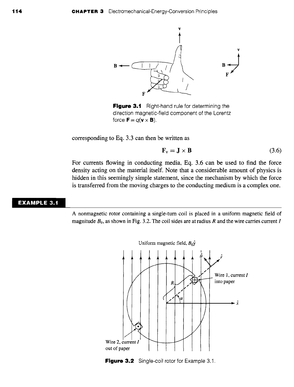
of v and B and the sine of the angle between them; its direction can be found from
the fight-hand rule, which states that when the thumb of the fight hand points in the
direction of v and the index finger points in the direction of B, the force, which is
perpendicular to the directions of both B and v, points in the direction normal to the
palm of the hand, as shown in Fig. 3.1.
For situations where large numbers of charged particles are in motion, it is con-
venient to rewrite Eq. 3.1 in terms of the charge density p (measured in units of
coulombs per cubic meter) as
Fv = p(E + v × B) (3.4)
where the subscript v indicates that Fv is a force density (force per unit volume) which
in SI units is measured in newtons per cubic meter.
The product p v is known as the current density
J = pv (3.5)
which has the units of amperes per square meter. The magnetic-system force density
114 CHAPTER 3 ElectromechanicaI-Energy-Conversion Principles
B <
F
¥
BJ
Figure
3.1 Right-hand rule for determining the
direction magnetic-field component of the Lorentz
force F = q(v x B).
corresponding to Eq. 3.3 can then be written as
Fv = J x B (3.6)
For currents flowing in conducting media, Eq. 3.6 can be used to find the force
density acting on the material itself. Note that a considerable amount of physics is
hidden in this seemingly simple statement, since the mechanism by which the force
is transferred from the moving charges to the conducting medium is a complex one.
"XAMPLE 3.
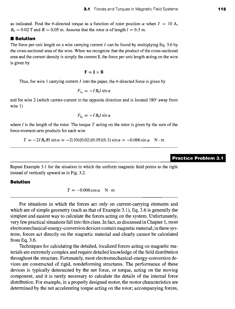
A nonmagnetic rotor containing a single-turn coil is placed in a uniform magnetic field of
magnitude B0, as shown in Fig. 3.2. The coil sides are at radius R and the wire carries current I
Uniform magnetic field, B0~
Wire 2, current I
out of paper
(
R,
/
J
,t
J
,t
J
\
/
/
Figure
3.2 Single-coil rotor for Example 3.1.
J
Wire 1, current I
into paper
3.1 Forces and Torques in Magnetic Field Systems 115
as indicated. Find the 0-directed torque as a function of rotor position ot when I - 10 A,
B0 = 0.02 T and R = 0.05 m. Assume that the rotor is of length l = 0.3 m.
II Solution
The force per unit length on a wire carrying current I can be found by multiplying Eq. 3.6 by
the cross-sectional area of the wire. When we recognize that the product of the cross-sectional
area and the current density is simply the current I, the force per unit length acting on the wire
is given by
F=I×B
Thus, for wire 1 carrying current I into the paper, the 0-directed force is given by
Flo = - I Bol
sin ct
and for wire 2 (which carries current in the opposite direction and is located 180 ° away from
wire 1)
F2o = - I Bol
sin ct
where I is the length of the rotor. The torque T acting on the rotor is given by the sum of the
force-moment-arm products for each wire
T = -2IBoRI
sin(~ = -2(10)(0.02)(0.05)(0.3) sinot = -0.006sinot N. m
Repeat Example 3.1 for the situation in which the uniform magnetic field points to the right
instead of vertically upward as in Fig. 3.2.
Solution
T = -0.006 cos ot N- m
For situations in which the forces act only on current-carrying elements and
which are of simple geometry (such as that of Example 3.1), Eq. 3.6 is generally the
simplest and easiest way to calculate the forces acting on the system. Unfortunately,
very few practical situations fall into this class. In fact, as discussed in Chapter 1, most
electromechanical-energy-conversion devices contain magnetic material; in these sys-
tems, forces act directly on the magnetic material and clearly cannot be calculated
from Eq. 3.6.
Techniques for calculating the detailed, localized forces acting on magnetic ma-
terials are extremely complex and require detailed knowledge of the field distribution
throughout the structure. Fortunately, most electromechanical-energy-conversion de-
vices are constructed of rigid, nondeforming structures. The performance of these
devices is typically determined by the net force, or torque, acting on the moving
component, and it is rarely necessary to calculate the details of the internal force
distribution. For example, in a properly designed motor, the motor characteristics are
determined by the net accelerating torque acting on the rotor; accompanying forces,