Fitzgerald A.E. Electric Machinery
Подождите немного. Документ загружается.

96 CHAPTER 2 Transformers
be chosen in the same ratio as the tums ratio of the transformer. Usually the rated or
nominal voltages of the respective sides are chosen. The process of referring quantities
to one side of the transformer is then taken care of automatically by using Eqs. 2.48
and 2.49 in finding and interpreting per-unit values.
This can be seen with reference to the equivalent circuit of Fig. 2.10c. If the base
voltages of the primary and secondary are chosen to be in the ratio of the turns of
the ideal transformer, the per-unit ideal transformer will have a unity turns ratio and
hence can be eliminated.
If these rules are followed, the procedure for performing system analyses in
per-unit can be summarized as follows:
1. Select a
VA
base and a base voltage at some point in the system.
2. Convert all quantities to per unit on the chosen
VA
base and with a voltage
base that transforms as the turns ratio of any transformer which is encountered
as one moves through the system.
3. Perform a standard electrical analysis with all quantities in per unit.
4. When the analysis is completed, all quantities can be converted back to real
units (e.g., volts, amperes, watts, etc.) by multiplying their per-unit values by
their corresponding base values.
When only one electric device, such as a transformer, is involved, the device's own
rating is generally used for the volt-ampere base. When expressed in per-unit form on
their rating as a base, the characteristics of power and distribution transformers do not
vary much over a wide range of ratings. For example, the exciting current is usually
between 0.02 and 0.06 per unit, the equivalent resistance is usually between 0.005 and
0.02 per unit (the smaller values applying to large transformers), and the equivalent
reactance is usually between 0.015 and 0.10 per unit (the larger values applying to
large high-voltage transformers). Similarly, the per-unit values of synchronous- and
induction-machine parameters fall within a relatively narrow range. The reason for
this is that the physics behind each type of device is the same and, in a crude sense,
they can each be considered to be simply scaled versions of the same basic device. As
a result, when normalized to their own rating, the effect of the scaling is eliminated
and the result is a set of per-unit parameter values which is quite similar over the
whole size range of that device.
Often, manufacturers supply device parameters in per unit on the device base.
When several devices are involved, however, an arbitrary choice of volt-ampere base
must usually be made, and that value must then be used for the overall system. As
a result, when performing a system analysis, it may be necessary to convert the sup-
plied per-unit parameter values to per-unit values on the base chosen for the analysis.
The following relations can be used to convert per-unit (pu) values from one base to
another:
I VAbase 11
( e, Q, gA )pu
on base
2 = ( e,
Q, VA )pu
on base 1 VAbase 2
( Vbase 1 ) 2
gAbase
2
(R, X,
Z)pu on base 2 =
(R, X,
Z)p u on base 1 (gbase 2)2 gAbase 1
(2.50)
(2.51)
2.9 The Per-Unit System 97
V base 1
Vpu on base 2 ~" Vpu on base l L Vbase 2
lpu on base 2 -" Ipu on base 1
Vbase 2 VAbase 1
Vbase 1 VAbase 2
(2.52)
(2.53)
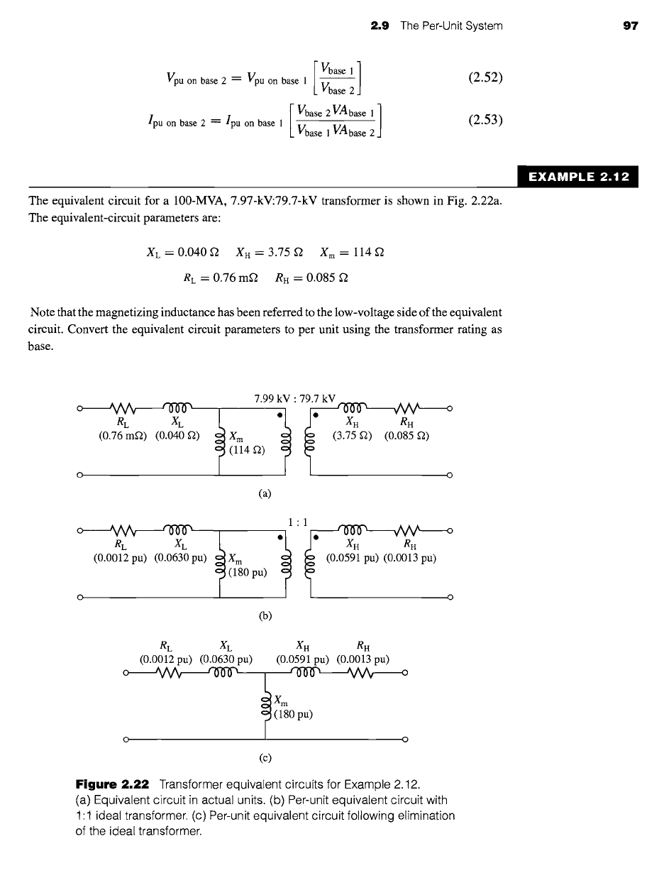
The equivalent circuit for a 100-MVA, 7.97-kV:79.7-kV transformer is shown in Fig. 2.22a.
The equivalent-circuit parameters are:
X L =
0.040 ~ XH = 3.75 ~
X m =
114 f2
RL "-"
0.76 mE2 RH = 0.085
Note that the magnetizing inductance has been referred to the low-voltage side of the equivalent
circuit. Convert the equivalent circuit parameters to per unit using the transformer rating as
base.
EXAMPLE 2.12
o ~ ~ 7.99 kV" kV ~ ,]Vv x o
RL XL XH RH
(0.76 m~) (0.040 g2) X m (3.75 ~) (0.085 ~)
(114 ~2)
o o
(a)
o 'V~ ~ 1.1 ~ ,A~ o
RL XL XH RH
(0.0012 pu) (0.0630 pu) X m (0.0591 pu) (0.0013 pu)
(180 pu)
O O
(b)
RL XL XH RH
(0.0012 pu) (0.0630 pu) (0.0591 pu) (0.0013 pu)
Xm
(180 pu)
o o
(c)
Figure 2.22 Transformer equivalent circuits for Example 2.12.
(a) Equivalent circuit in actual units. (b) Per-unit equivalent circuit with
1:1 ideal transformer. (c) Per-unit equivalent circuit following elimination
of the ideal transformer.
98
CHAPTER 2 Transformers
m Solution
The base quantities for the transformer are:
Low-voltage side:
VAbase = 100 MVA
Vbase = 7.97 kV
and from Eqs. 2.48 and 2.49
vLo
Rbase -- Xbase : ---0.635 f2
Vmbase
High-voltage side:
VAbase = 100 MVA
Vbase =
79.7 kV
and from Eqs. 2.48 and 2.49
V~ase
Rbase = Xbase = -- 63.5 g2
Vmbase
The per-unit values of the transformer parameters can now be calculated by division by
their corresponding base quantities.
0.040
XL = -- 0.0630 per unit
0.635
3.75
XH = = 0.0591 per unit
63.5
114
Xm = 0.635 = 180 per unit
7.6
x 10 -4
RL = = 0.0012 per unit
0.635
0.085
R. = = 0.0013 per unit
63.5
Finally, the voltages representing the turns ratio of the ideal transformer must each be di-
vided by the base voltage on that side of the transformer. Thus the turns ratio of 7.97-kV:79.7-kV
becomes in per unit
(7.97 kV)(79.7 kV)
Per-unit turns ratio= 7.97kV " 79.7kV = 1" 1
The resultant per-unit equivalent circuit is shown in Fig. 2.22b. Because it has unity turns ratio,
there is no need to keep the ideal transformer and hence this equivalent circuit can be reduced
to the form of Fig. 2.22c.
EXAMPLE 2.13
The exciting current measured on the low-voltage side of a 50-kVA, 2400:240-V transformer
is 5.41 A. Its equivalent impedance referred to the high-voltage side is 1.42 + j 1.82 ~. Using
the transformer rating as the base, express in per unit on the low- and high-voltage sides (a) the
exciting current and (b) the equivalent impedance.
2.9 The Per-Unit System 99
II Solution
The base values of voltages and currents are
Vb .... H
= 2400 V Vb .... L = 240 V lb
.... H =
20.8 A Ib .... L = 208 A
where subscripts H and L indicate the high- and low-voltage sides, respectively.
From Eq. 2.49
2400 240
Zb .... H
= 20.8 -- 115.2 f2
Z b .... L =
208
-- 1.152 f2
a. From Eq. 2.47, the exciting current in per unit referred to the low-voltage side can be
calculated as:
5.41
l~,e = 208 = 0.0260 per unit
The exciting current referred to the high-voltage side is 0.541 A. Its per-unit value is
0.541
le,n = 20.8 = 0.0260 per unit
Note that, as expected, the per-unit values are the same referred to either side,
corresponding to a unity turns ratio for the ideal transformer in the per-unit transformer.
This is a direct consequence of the choice of base voltages in the ratio of the transformer
turns ratio and the choice of a constant volt-ampere base.
b. From Eq. 2.47 and the value for
Zbase
1.42 + j 1.82
Zeq'H =
115.2 = 0.0123 + j0.0158 per unit
The equivalent impedance referred to the low-voltage side is 0.0142 + j0.0182~2. Its
per-unit value is
Zeq, L
0.142 + 0.0182
1.152
= 0.0123 + j0.0158 per unit
The per-unit values referred to the high- and low-voltage sides are the same, the
transformer turns ratio being accounted for in per unit by the base values. Note again that
this is consistent with a unity turns ratio of the ideal transformer in the per-unit
transformer equivalent circuit.
~ractice Problem 2.1q
A 15-kVA 120:460-V transformer has an equivalent series impedance of 0.018 + j0.042 per
unit. Calculate the equivalent series impedance in ohms (a) referred to the low-voltage side
and (b) referred to the high-voltage side.
Solution
Zeq,L ~--
0.017 + j0.040 g2 and Zeq,n = 0.25 + j0.60 f2
When they are applied to the analysis of three-phase systems, the base values for
the per-unit system are chosen so that the relations for a balanced three-phase system
100
CHAPTER 2 Transformers
hold between them:
(Pbase, Qbase, VAbase)3-phase = 3 VAbase, per phase
(2.54)
In dealing with three-phase systems, VAbase ' 3-phase, the three-phase volt-ampere base,
and
Vbase ' 3-phase =
Vbase, 1-1, the line-to-line voltage base are usually chosen first. The
base values for the phase (line-to-neutral) voltage then follows as
1
Vbase, 1-n -- ~ Vbase, 1-1 (2.55)
Note that the base current for three-phase systems is equal to the phase current,
which is the same as the base current for a single-phase (per-phase) analysis. Hence
/base, 3-phase : /base, per phase =
VAbase, 3-phase
"V/3 Vbase, 3-phase
(2.56)
Finally, the three-phase base impedance is chosen to the be the single-phase base
impedance. Thus
Zbase, 3-phase ~--- Zbase, per phase
Vbase, l-n
/base, per phase
Vbase, 3-phase
'W/-31base, 3-phase
( Vbase, 3-phase) 2
VA base, 3-phase
(2.57)
The equations for conversion from base to base, Eqs. 2.50 through 2.53, apply
equally to three-phase base conversion. Note that the factors of ~ and 3 relating
A to Y quantities of volts, amperes, and ohms in a balanced three-phase system are
automatically taken care of in per unit by the base values. Three-phase problems can
thus be solved in per unit as if they were single-phase problems and the details of
transformer (Y vs A on the primary and secondary of the transformer) and impedance
(Y vs A) connections disappear, except in translating volt, ampere, and ohm values
into and out of the per-unit system.
EXAMPLE 2.14
Rework Example 2.9 in per unit, specifically calculating the short-circuit phase currents which
will flow in the feeder and at the 240-V terminals of the receiving-end transformer bank.
Perform the calculations in per unit on the three-phase, 150-kVA, rated-voltage base of the
receiving-end transformer.
II
Solution
We start by converting all the impedances to per unit. The impedance of the 500-kVA,
24 kV:2400 V sending end transformer is 0.17 + j0.92 f2/phase as referred to the 2400-V
2.9 The Per-Unit System 101
side. From Eq. 2.57, the base impedance corresponding to a 2400-V, 150-kVA base is
24002
Zbase "- "-
3 8.4 f2
150 × 103
From Example 2.9, the total series impedance is equal to
Zto t --
0.64 + j2.33 Q/phase and
thus in per unit it is equal to
Ztot ---
0.64 + j2.33
38.4
= 0.0167 + j0.0607 per unit
which is of magnitude
[Ztotl = 0.0629 per unit
The voltage applied to the high-voltage side of the sending-end transformer is Vs =
24.0 kV = 1.0 per unit on a rated-voltage base and hence the short-circuit current will equal
Vs 1.0
lsc = = = 15.9 per unit
[Ztot[ 0.0629
To calculate the phase currents in amperes, it is simply necessary to multiply the per-
unit short-circuit current by the appropriate base current. Thus, at the 2400-V feeder the base
current is
150 x 103
-- = 36.1A
Ib .... 2400-v -- V~ 2400
and hence the feeder current will be
/feeder =
15.9 x 36.1 = 574 A
The base current at the 240-V secondary of the receiving-end transformers is
150 × 103
- = 361A
Ib ....
240-V -- ~ 240
and hence the short-circuit current is
I240-V .....
dary = 15.9 X 361 = 5.74 kA
As expected, these values are equivalent within numerical accuracy to those calculated in
Example 2.9.
)ractice Problem 2.1'
Calculate the magnitude of the short-circuit current in the feeder of Example 2.9 if the 2400-
V feeder is replaced by a feeder with an impedance of 0.07 + j0.68 g2/phase. Perform this
calculation on the 500-kVA, rated-voltage base of the sending-end transformer and express
your solution both in per unit and in amperes per phase.
Solution
Short-circuit current = 5.20 per unit -- 636 A
102 CHAPTER 2 Transformers
EXAMPLE 2.15
A three-phase load is supplied from a 2.4-kV:460-V, 250-kVA transformer whose equivalent
series impedance is 0.026 + j0.12 per unit on its own base. The load voltage is observed to
be 438-V line-line, and it is drawing 95 kW at unity power factor. Calculate the voltage at the
high-voltage side of the transformer. Perform the calculations on a 460-V, 100-kVA base.
II
Solution
The 460-V side base impedance for the transformer is
4602
m
Zb .... transformer- 250 X 103
= 0.846 f2
while that based upon a 100-kVA base is
4602
Zb ....
100-kVA = = 2.12 f2
100 X 103
Thus, from Eq. 2.51 the per-unit transformer impedance on a 100-kVA base is
0.864 "~
Ztr..sformer = (0.026 + jO.12) \ 2.12 J = 0.0106 + j.0489 per unit
The per unit load voltage is
438
~oad = = 0.952/0 ° per unit
460
where the load voltage has been chosen as the reference for phase-angle calculations.
The per-unit load power is
95
eload -" = 0.95 per unit
100
and hence the per-unit load current, which is in phase with the load voltage because the load is
operating at unity power factor, is
iloa d
= Pload =
0.95 = 0.998/0 ° per unit
Vload 0.952
Thus we can now calculate the high-side voltage of the transformer
I~)'H = Vload + iloadZt .... former
= 0.952 + 0.998(0.0106 + j0.0489)
= 0.963 + j0.0488 = 0.964 L29.0 ° per unit
Thus the high-side voltage is equal to 0.964 x 2400 V = 2313 V (line-line).
2.10 Summary 103
)ractice Problem 2.1:
Repeat Example 2.15 if the 250-kV three-phase transformer is replaced by a 150-kV transformer
also rated at 2.4-kV:460-V and whose equivalent series impedance is 0.038 + j0.135 per unit
on its own base. Perform the calculations on a 460-V, 100-kVA base.
Solution
High-side voltage = 0.982 per unit = 2357 V (line-line)
2.10 SUMMARY
Although not an electromechanical device, the transformer is a common and indis-
pensable component of ac systems where it is used to transform voltages, currents,
and impedances to appropriate levels for optimal use. For the purposes of our study of
electromechanical systems, transformers serve as valuable examples of the analysis
techniques which must be employed. They offer us opportunities to investigate the
properties of magnetic circuits, including the concepts of mmf, magnetizing current,
and magnetizing, mutual, and leakage fluxes and their associated inductances.
In both transformers and rotating machines, a magnetic field is created by the
combined action of the currents in the windings. In an iron-core transformer, most
of this flux is confined to the core and links all the windings. This resultant mutual
flux induces voltages in the windings proportional to their number of turns and is
responsible for the voltage-changing property of a transformer. In rotating machines,
the situation is similar, although there is an air gap which separates the rotating and
stationary components of the machine. Directly analogous to the manner in which
transformer core flux links the various windings on a transformer core, the mutual flux
in rotating machines crosses the air gap, linking the windings on the rotor and stator.
As in a transformer, the mutual flux induces voltages in these windings proportional
to the number of turns and the time rate of change of the flux.
A significant difference between transformers and rotating machines is that in ro-
tating machines there is relative motion between the windings on the rotor and stator.
This relative motion produces an additional component of the time rate of change of the
various winding flux linkages. As will be discussed in Chapter 3, the resultant voltage
component, known as the
speed voltage,
is characteristic of the process of electrome-
chanical energy conversion. In a static transformer, however, the time variation of flux
linkages is caused simply by the time variation of winding currents; no mechanical
motion is involved, and no electromechanical energy conversion takes place.
The resultant core flux in a transformer induces a counter emf in the primary
which, together with the primary resistance and leakage-reactance voltage drops,
must balance the applied voltage. Since the resistance and leakage-reactance voltage
drops usually are small, the counter emf must approximately equal the applied voltage
and the core flux must adjust itself accordingly. Exactly similar phenomena must take
place in the armature windings of an ac motor; the resultant air-gap flux wave must
adjust itself to generate a counter emf approximately equal to the applied voltage.
104 CHAPTER 2 Transformers
In both transformers and rotating machines, the net mmf of all the currents must
accordingly adjust itself to create the resultant flux required by this voltage balance.
In any ac electromagnetic device in which the resistance and leakage-reactance voltage
drops are small, the resultant flux is very nearly determined by the applied voltage
and frequency, and the currents must adjust themselves accordingly to produce the
mmf required to create this flux.
In a transformer, the secondary current is determined by the voltage induced in the
secondary, the secondary leakage impedance, and the electric load. In an induction
motor, the secondary (rotor) current is determined by the voltage induced in the
secondary, the secondary leakage impedance, and the mechanical load on its shaft.
Essentially the same phenomena take place in the primary winding of the transformer
and in the armature (stator) windings of induction and synchronous motors. In all
three, the primary, or armature, current must adjust itself so that the combined mmf
of all currents creates the flux required by the applied voltage.
In addition to the useful mutual fluxes, in both transformers and rotating ma-
chines there are leakage fluxes which link individual windings without linking oth-
ers. Although the detailed picture of the leakage fluxes in rotating machines is more
complicated than that in transformers, their effects are essentially the same. In both,
the leakage fluxes induce voltages in ac windings which are accounted for as leakage-
reactance voltage drops. In both, the reluctances of the leakage-flux paths are domi-
nanted by that of a path through air, and hence the leakage fluxes are nearly linearly
proportional to the currents producing them. The leakage reactances therefore are
often assumed to be constant, independent of the degree of saturation of the main
magnetic circuit.
Further examples of the basic similarities between transformers and rotating
machines can be cited. Except for friction and windage, the losses in transformers
and rotating machines are essentially the same. Tests for determining the losses and
equivalent circuit parameters are similar: an open-circuit, or no-load, test gives in-
formation regarding the excitation requirements and core losses (along with friction
and windage losses in rotating machines), while a short-circuit test together with dc
resistance measurements gives information regarding leakage reactances and wind-
ing resistances. Modeling of the effects of magnetic saturation is another example:
In both transformers and ac rotating machines, the leakage reactances are usually as-
sumed to be unaffected by saturation, and the saturation of the main magnetic circuit
is assumed to be determined by the resultant mutual or air-gap flux.
2.11 PROBLEMS
2.1 A transformer is made up of a 1200-turn primary coil and an open-circuited
75-turn secondary coil wound around a closed core of cross-sectional area
42 cm 2. The core material can be considered to saturate when the rms applied
flux density reaches 1.45 T. What maximum 60-Hz rms primary voltage is
possible without reaching this saturation level? What is the corresponding
secondary voltage? How are these values modified if the applied frequency is
lowered to 50 Hz?
2.11 Problems 105
2.2 A magnetic circuit with a cross-sectional area of 15 cm 2 is to be operated at
60 Hz from a 120-V rms supply. Calculate the number of turns required to
achieve a peak magnetic flux density of 1.8 T in the core.
2.3 A transformer is to be used to transform the impedance of a 8-fl resistor to an
impedance of 75 ft. Calculate the required turns ratio, assuming the
transformer to be ideal.
2.4 A 100-fl resistor is connected to the secondary of an idea transformer with a
turns ratio of 1:4 (primary to secondary). A 10-V rms, 1-kHz voltage source is
connected to the primary. Calculate the primary current and the voltage across
the 100-f2 resistor.
2.5 A source which can be represented by a voltage source of 8 V rms in series
with an internal resistance of 2 kfl is connected to a 50-f2 load resistance
through an ideal transformer. Calculate the value of turns ratio for which
maximum power is supplied to the load and the corresponding load power?
Using MATLAB, plot the the power in milliwatts supplied to the load as a
function of the transformer ratio, covering ratios from 1.0 to 10.0.
2.6 Repeat Problem 2.5 with the source resistance replaced by a 2-kf2 reactance.
2.7 A single-phase 60-Hz transformer has a nameplate voltage rating of
7.97 kV:266 V, which is based on its winding turns ratio. The manufacturer
calculates that the primary (7.97-kV) leakage inductance is 165 mH and the
primary magnetizing inductance is 135 H. For an applied primary voltage of
7970 V at 60 Hz, calculate the resultant open-circuit secondary voltage.
2.8 The manufacturer calculates that the transformer of Problem 2.7 has a
secondary leakage inductance of 0.225 mH.
a. Calculate the magnetizing inductance as referred to the secondary side.
b. A voltage of 266 V, 60 Hz is applied to the secondary. Calculate (i) the
resultant open-circuit primary voltage and
(ii)
the secondary current
which would result if the primary were short-circuited.
2.9 A 120-V:2400-V, 60-Hz, 50-kVA transformer has a magnetizing reactance
(as measured from the 120-V terminals) of 34.6 ft. The 120-V winding has a
leakage reactance of 27.4 mr2 and the 2400-V winding has a leakage
reactance of 11.2 ft.
a. With the secondary open-circuited and 120 V applied to the primary
(120-V) winding, calculate the primary current and the secondary voltage.
b. With the secondary short-circuited, calculate the primary voltage which
will result in rated current in the primary winding. Calculate the
corresponding current in the secondary winding.
2.10 A 460-V:2400-V transformer has a series leakage reactance of 37.2 f2 as
referred to the high-voltage side. A load connected to the low-voltage side is
observed to be absorbing 25 kW, unity power factor, and the voltage is
measured to be 450 V. Calculate the corresponding voltage and power factor
as measured at the high-voltage terminals.