Fahlman B.D. Materials Chemistry
Подождите немного. Документ загружается.

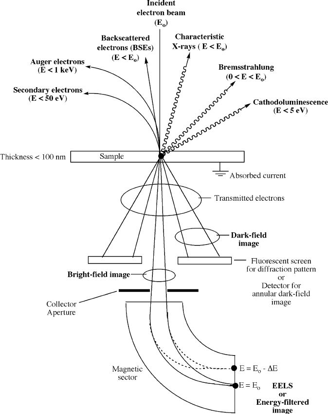
Figure 7.26. Illustration of beam-specimen interactions within a transmission electron microscope.
618 7 Materials Characterization
Consequently, SEM provides information regarding the species present at varying
depths of the sample (Figure 7.27):
(i) Elastic scattering of electrons by atomic nuclei of the sample results in BSE –
useful for generating images based on Z-contrast (Figure 7.28).
(ii) Inelastic scattering of electrons by sample atoms results in low-energy second-
ary electrons (SE) useful for providing topographic information regarding the
sample surface.
(iii) Inelastic scattering of electrons by sample atoms results in X-ray generation
(characteristic and Bremsstrahlung background X-rays) from lower sample
depths – useful for chemical analysis of the bulk sample.
(iv) Inelastic scattering resu lts in Auger electrons emitted from sample atoms near
the sample surface – useful for surface chemical analysis.
As you will recall from Figure 7.6b, for imaging and chemical analysis using SEM,
the particles generated from the sample must reach the detector situated above the
sample surface. Since the relative energies of the generated particles are in the order:
Auger electrons < SE < BSE < X-rays
The least energetic emissions will not reac h the surface from lower depths of the
sample. For instance, Auger electrons that are emitted from deeper regions of
Primary electron beam
(ca. 1 - 10 nm diameter)
Sample surface
Interaction
volume
(0.5 - 2 µm)
Bremsstrahlung
(continuous X-rays)
Characteristic
X-rays
Backscattered
electrons (BSE)
Secondary electrons (SE)
Auger electrons
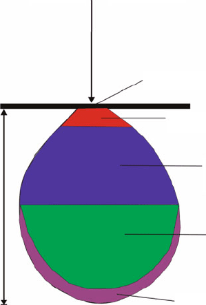
Figure 7.27. Illustration of the sample interaction volume, and the corresponding particles emitted from
various sample depths. The exact volume will depend on the accelerating voltage of the electron beam and
sample composition.
7.2. Electron Micros copy 619
the sample lose their energy through collisions with sample atoms before they reach
the surface. As a result, AES is a very sensitive technique to probe the chemical
composition of only the top 50–100 A
˚
(i.e., 15–30 monolayers). In comparison, the
maximum escape depth of secondary electrons has been estimated as 5 nm in metals,
and 50 nm in insulators.
Not surprisingly, both the beam current (or accelerating voltage) and sample
density will greatly affect the interaction volume of the bulk sample with primary
electrons (Figures 7.29 and 7.30, respectively). As we saw earlier, the probability for
elastic scattering increases with Z
2
(Eq. 9); hence, as the density of the sample
increases, the number of BSEs will increase, reducing the numb er of electrons that
may penetrate to deeper regions of the sample. Similarly, as the energy of the
incident beam decreases, fewer inelastic collisions with sample atoms are needed
to bring the electrons to rest, thus decreasing the penetration depth into the sample .
The image formed from SEM is primarily the result of secondary electron
emission from sample surface. The Law of Conservation of Energy ensures that
any energy lost by the primary beam electrons must be transferred to the secondary
electrons that are ejected from the sample atoms.
[61]
Those with sufficient energy to
traverse the sample surface reach an Everhart–Thornley detector, which consists of a
scintillator and photomultiplier tube (PMT).
[62]
The topographical contrast that
arises from an uneven surface is due to a differing number of SEs being released
from the sample (Figure 7.31).
Structure determination using SEM
In addition to displaying the familiar bright-field images from secondary electron
emission, BSE in a SEM may be used to determine the crystallography of (poly)
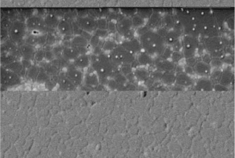
Figure 7.28. The image illustrates two different scanning modes of a scanning electron microscope
(SEM). In the lower part of the image, we can see the relief of the sample. This is obtained using the
detection of secondary electrons. In the upper part of the image, we can see light spots surrounded by
darker areas. The light spots correspond to the zirconium aggregates in an aluminium matrix. This is
obtained using the detection of backscattered electrons.
620 7 Materials Characterization
–5018.9 nm –2509.4 nm 0.0 nm 2509.4 nm 5018.9 nm
–5018.9 nm –2509.4 nm 0.0 nm 2509.4 nm 5018.9 nm
–5018.9 nm –2509.4 nm
0.0 nm 2509.4 nm
5018.9 nm
0.0 nm
1900.0 nm
3800.0 nm
5700.0 nm
7600.0 nm
0.0 nm
1900.0 nm
Silicon
Silicon
Silicon
3800.0 nm
5700.0 nm
7600.0 nm
0.0 nm
1900.0 nm
3800.0 nm
5700.0 nm
7600.0 nm
1900 nm
a
b
c
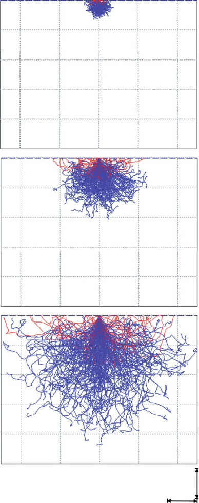
Figure 7.29. Electron-beam penetration volume resulting from varying the beam current. Shown are
X-rays (blue) and backscattered electrons (red) generated from a silicon substrate. The beam currents
are (a) 10 keV, (b) 20 keV, and (c) 30 keV.
[60]
7.2. Electron Micros copy 621
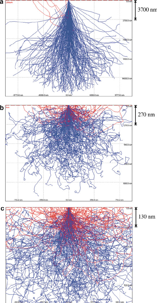
Figure 7.30. Electron-beam penetration volume resulting from varying the sample density. Shown are
X-rays (blue) and backscattered electrons (red) resulting from electron beam impingement on (a) Li,
(b) Fe, and (c) Pb. The beam current is 20 keV, and beam diameter 10 nm for all metals.
[60]
622 7 Materials Characterization
crystalline samples. This technique is referred to as electron backscattering diffraction
(EBSD) or backscattering Kikuchi diffraction (BKD), used to measure individual
crystallite orientations, as well as crystallographic parameters of the sample (e.g.,
interplane spacings/angles, crystal symmetry elements, etc.). The EBSD patterns are
generated from the interaction of the incident electron beam with a highly tilted (ca.70
from horizontal) planar sample.
When the electrons impinge on the crystalline sample, they interact with individual
lattice planes. When these interactions satisfy the Bragg condition, they exhibit
backscattering diffraction and (due to the tilted sample) are directed toward a phos-
phor screen where the fluorescent pattern is detected by a CCD camera. The resulting
pattern consists of a large number of intersecting bands, known as Kikuchi lines,
which represent the unique crystallographic properties of the crystal (Figure 7.32a).
Computer software is used to collect/analyze the resulting patterns to determine the
crystallography of the material.
[63]
In association with compositional data from EDS,
the exact phase of the material may be identified from a library of known materials.
For a more thorough crystallographic description, orientation imaging microscopy
(OIM) is often carried out in tandem with EBSD. This technique consists of stepping
the beam across the sample, with automatic indexing of the resulting EBSD patterns.
The resulting OIM map readily reveals the crystallographic orientations and grain
boundaries in three-dimensions (Figure 7.32b) – of use for applications such as sensor/
heterogeneous catalyst design and micro/nano defect analyses.
Sample considerations
Sample preparation for SEM analysis is trivial relative to TEM, with the sample
simply deposited onto the top of an adhesive fastened to an aluminum stub/holder.
Most often, conductive carbon tape is used to sequester the sample; for FESEM,
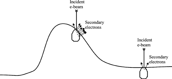
Figure 7.31. Illustration of topographic imaging of a surface using SEM. When the incident beam strikes
the side of a feature, many secondary electrons are released from the side and top of the interaction volume
(“edge effect”). In comparison, the interaction of the primary beam with a flat substrate releases
significantly fewer secondary electrons that originate near the sample surface. The image contrast
results from varying numbers of secondary electrons reaching the detector as the beam is rastered
across the sample surface.
7.2. Electron Micros copy 623
problems with outgassing usually dictates the use of carbon/silver paint, epoxy, or
copper/aluminum tape with adequate drying prior to analysis. After allowing
the solvent to fully evaporate (if present), a thin conductive film (ca. <10 nm) of
Au or C is often deposited onto the sample surface.
[64]
This is especially required
if a non-conductive adhesive is used to mount the sample, or if the sample itself
is non-conductive. The preparative steps involving conductive mounting materials is
important to prevent charging – the buildup of electrons on the sample surface, which
dramatically affects the imaging ability of the SEM (Figure 7.33). Sometimes, it is
even necessary to use an additional amount of carbon paste or tape to create a
conductive path between a tall sample and the aluminum holder. It should be noted
that metallic coatings also serve another important use – to increase the SE emission of
a sample with a low yield of secondary electrons (e.g., comprising low-Z elements).
Elemental analyses
In addition to imaging applications, SEM is also widel y used for elemental analysis
and chemical mapping of surfaces, using EDS/WDS. However, unlike TEM, facile
cross-section imaging/chemical mapping may also be performed using specialized
sample holders (Figure 7.34). Besides monitoring characteristic X-rays from sample
elements, Auger electron emission may be analyzed – a technique known as auger
electron spectros copy , AES (Figure 7.35a). Analogous to the STEM extension of
TEM, scanning auger microscopy (SAM) is also possible, wherein the incident
electron beam is scanned across the sample. Perhaps the most intriguing aspect of
AES/SAM instruments is the capability of depth profiling. An argon ion beam is
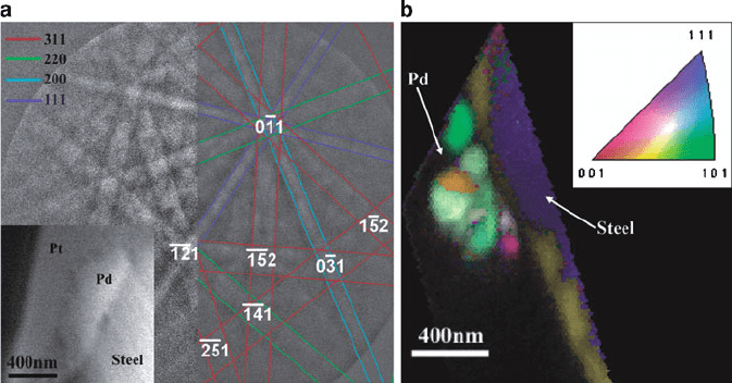
Figure 7.32. (a) SEM micrograph (left bottom inset) of a Pd particulate selected for crystallographic
analysis. Also shown are the crisscrossing Kikuchi lines originating from various crystallographic planes.
The indices of each plane are indicated in the color legend at the top-left corner. (b) The orientation
imaging microscopic (OIM) profile of the Pd particulate, showing a microcrystalline array (color-coated
based on the crystallite orientations). Reproduced with permission from Bera, D.; Kuiry, S. C.; Seal, S.
J. Phys. Chem. B 2004, 108, 556. Copyright 2004 American Chemical Society.
624 7 Materials Characterization
used to etch away monolayers of the surface, allowing for com positional studies as a
function of sample depth (Figure 7.35b).
A simple way to distinguish between SEM and SAM is the former collects
secondary electrons to form an image; the latter collects Auger electrons for chemical
analysis. Recent developments have now afforded dual-detector electron microscopes
that are equipped with standard FESEM/EDS capabilities in addition to SAM. This
powerful combination offers the direct superimposing of both EDS and SAM chemi-
cal maps onto the corresponding high-resolution image.
[68]
In addition to being more
sensitive for light elements ( 0.5 at% for Li–U), it should be noted that AES is more
suited for surface analysis than EDS. Due to the low kinetic energies of Auger
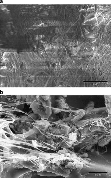
Figure 7.33. SEM images of amorphous carbon nanofibers (nonconductive) grown at room temperature
from a dendritic catalyst. Shown is (a) as-formed nanofibers, without a gold coating and (b) after sputtering
a thin conductive gold coating on the surface. The uncoated sample exhibited extreme charging (a), which
thermally degraded the sample and caused movement of the sample during imaging.
[65]
7.2. Electron Micros copy 625
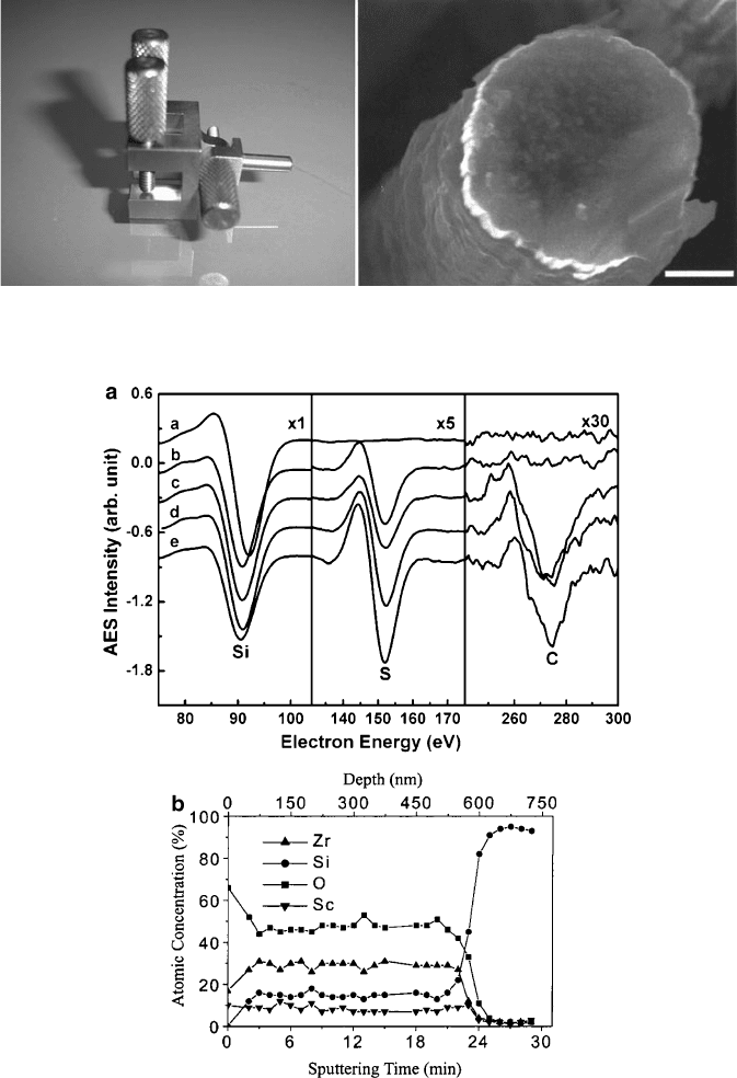
Figure 7.35. (a) AES analysis of organosulfur compounds adsorbed onto Si(100). Shown are the Si
(LVV), S(LVV), and C(KLL) transitions for (a) clean Si(100), and after saturation exposure by (b) H
2
S,
(c) CH
3
SCH
3
, (d) CH
3
SH, and (e) CH
3
SSCH
3
.
[62]
(b) AES depth profile for a (Sc
2
O
3
)
0.08
(ZrO
2
)
0.92
thin
film deposited onto a Si(100) wafer. This profile shows a homogeneous Sc:Zr:O:Si atomic ratio between
75 and 500 nm, with an interdiffusion layer thickness of <100 nm. By examining the rise of the Si peak,
the film thickness can be readily determined.
[67]
Figure 7.34. Photograph of a variable-angle SEM sample holder, with an example of a cross-section SEM
image (scale bar is 2 mm).
[66]
626 7 Materials Characterization
electrons (ca. 50 eV–3 keV), chemical information is only obtained from sample
depths of ca. <50 A
˚
(compared to 1–2 mm for EDS). As such, it is not always possible
to coat the sample to prevent charging, which explains why SAM is most often applied
for compositional studies of conductive samples.
[69]
Environmental or in-situ electron microscopy
Though the analysis of sam ples in the presence of solvent is normally a faux pas
for the UHV environment of any electron microscope, there are now instruments
known as environmental electron microscopes (also known as in situ elect ron
microscopes
[70]
) that are capable of such studies. These instruments have been in
development since the early 1970s,
[71]
for in situ studies of virtua lly any material
(wet/dry, insulating/conducting). Before this major technological development,
samples such as paints, inks, and biological specimens had to be dried completely
to maintain the integrity of the vacuum system. Typically, an environmental electron
microscope is not simply a modified EM, but rather a specially designed instrument
that is capable of regular imaging, as well as high-resolution
[72]
operation under
atypical conditions such as within liquid media, at high temperature, etc.
The operation of an environmental SEM (ESEM) is made possible through use of
a different ial pumping system (Figure 7.36) that maintains a UHV environment
(10
7
Torr) required for the electron gun, while allowing the presence of gases in the
sample chamber (10–20 Torr). The pressure and temperature of the sample chamber
may be strictly controlled, inducing evaporation or condensation events. The non-
vacuum conditions within the sample chamber require a different type of detection
system relative to conven tional SEMs, referred to as a gaseous secondary electron
detector (GSED). Due to the energetic nature of the primary beam , there is little
scatter from its interaction with the gaseous medium about the sample. En route
toward the positive electrode, the secondary electrons generated from the sample
repeatedly collide with gas molecules, generating a cascade of additional electrons
and positive ions (Figure 7.36). In addition to amplifying the SE signal, the positive
ions migrate back to the sample surface where they dissipate the charge buildup –
hence, precluding the need for conductive samples or carbon/gold coating. The
aperture diameter through which the primary electron beam is passed determines
the overall maximum pressure of the sample chamber. For instance, a 0.5 mm
aperture dictates a maximum pressure of 10 Torr about the sample; a 1 mm aperture
would lower the maximum pres sure to 5 Torr.
For in situ TEM, a sample compartment with positive pressure is generated by
placing a series of restricting apertures in the column near the pole piece, yielding
regions of lower-pressure above/below the sample (Figure 7.37). It should be noted
that in situ TEM studies may also be carried out within a conventional instrument.
Rather than permanently modifying the TEM column with a differential pumping
system, a sealed chamber with electron-transpa rent windows is used to maintain a
pressurized atmosphere around the sample.
[73]
TEMs may now be fitted with a
number of specialized objective lens pole-pieces (Figure 7.37) that will allow one
7.2. Electron Micros copy 627