Ellis,J. Pressure transients in water engineering, A guide to analysis and interpretation of behaviour
Подождите немного. Документ загружается.

20.5 Reopening of a check valve door
Depending upon the characteristics of a system, such as pumping head,
static lift, etc., a check valve may reopen after initial closure. There may
be an elastic rebound of the valve door just after seating. This could
be caused by reflection of elastic waves travelling longitudinally in
the pipe wall or by reflection of pressure waves in the liquid. In addition,
as the surge progresses in the system as a whole, head downstream of the
382
.
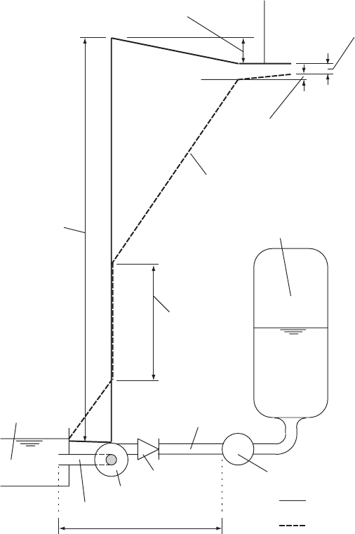
Steady pumping
hydraulic gradient
Hydraulic gradient
durin
g
deceleration
Head loss in
discharge branch
Steady pumping head
in manifold
Fall in head in vessel
due to gas expansion
Head in discharge
manifold during
pump deceleration
Head loss in vessel
connection during outflow
Adverse hydraulic gradient
producing rapid deceleration
of flow in pump branch
Pressure vessel
Pumping head as
pump decelerates
Pumping head during
steady operation
Suction well
M
M
Discharge branch
Discharge manifold
or header
NRV
L
Failing pump
Suction branch
Fig. 20.4. Hydraulic gradient in a pumping station shortly after pump trip
Pressure transients in water engineering
check valve may fall below the upstream head in say a wet well or
suction main and forward flow may recommence with the check
valve partially reopening. A check valve installed within a bypass
around the pump(s) would also open under these circumstances. This
can occur several times before the valve finally remains shut. The
following cases illustrate both types of valve reopening.
20.5.1 Check valve reopening due to pressure wave reflections
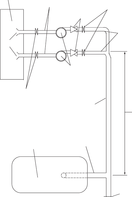
A simple case involves a water scheme in which two pumps may operate
in parallel. Figure 20.5 shows the fairly typical layout of the pumping
383
DN 100 NRV
Non-reflecting boundary
at start of risin
g
main
Pressure vessel
Surge vessel branch
DN 200 common header
DN 125 isolating valve
WPL Duoglide
DQC 100/125
8 m
Intake
DN 125 suction branches
DN 150 isolating valve
DN 150 discharge branch
Suction well +2.0 – +4.0
Fig. 20.5. Pumping station layout
Check valve dynamics
station. Weir Pumps Limited Duoglide units type DQC 100/125 were
employed. A pressure vessel was connected 8 m downstream of the
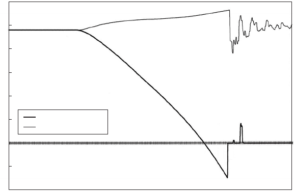
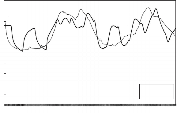
second pump branch. Figure 20.6 shows the changing velocity just
downstream of the check valve of a failing pump and also downstream
of the valve of the remaining operating pump. After trip at 0.1 s the
velocity falls steeply and reverses at 0.285 s. A reversed velocity of
0.3 m/s is achieved at the time the check valve closes after about
0.37 s. Velocity becomes zero and remains so until pressure wave reflec-
tions cause head across the valve to allow a brief interval of reopening
before the valve finally shuts. Velocity in the operating pump branch
increases until the first check valve shuts and then falls with a
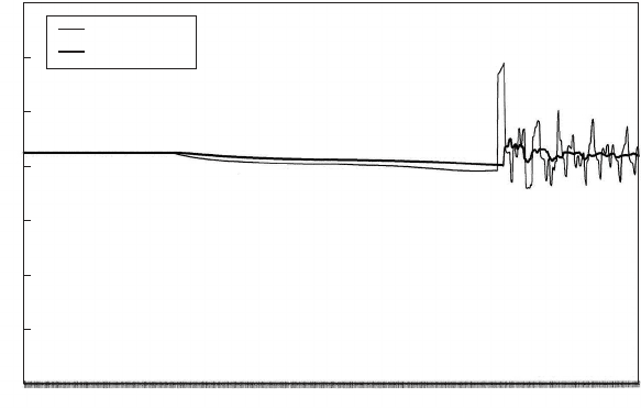
modest oscillation developing. Changing head downstream of the
check valves can be seen in Fig. 20.7, with an abrupt upsurge when
the check valve of pump No. 1 closes. Peak head is almost 120 m
above datum. Steady pumping head is around 84 mAOD. Head down-
stream of the second pump falls to a lesser extent. Wave reflection
causes head downstream of the failing pump to reach a minimum and
it is at this time that the check valve briefly reopens. A smaller head
variation occurs at the operating pump. The reason that the check
valve is able to reopen under such high head conditions is because
the pump is still rotating at around 85% of its design speed at the
time of valve closure. The reduced head developed by the pump is
still sufficient to reopen the check valve when downstream head falls.
384
0.001
0.015
0.029
0.043
0.057
0.071
0.085
0.100
0.114
0.128
0.142
0.156
0.170
0.184
0.198
0.212
0.227
0.241
0.255
0.269
0.283
0.297
0.311
0.325
0.339
0.354
0.368
0.382
0.396
0.410
Time (s)
Pump delivery No. 1
Pump delivery No. 2
Velocity (m/s)
1.2
1.0
0.8
0.6
0.4
0.2
0
–0.2
–0.4
Fig. 20.6. Velocities at failing/operating pump
Pressure transients in water engineering
As pump speed continues to decrease over time, head upstream of the
valve diminishes and the check valve remains closed.
Check valve reopening as a consequence of pressure wave reflection
is an event that will occur shortly after valve closure and can usually be
predicted by the ‘local’ type of model.
20.5.2 Valve reopening in longer term
Valve reopening in the longer term as a consequence of transient
behaviour in the system as a whole will only be predicted by a model
of the complete system, or a substantial part thereof. As an example
of this second form of behaviour, consider the case of the Abu Dhabi
sewage pumping system from pumping station No. 5 to Mafraq Waste
Water Treatment Works (WWTW), a distance of 13 343.6 m. Two
mains are used: an older pipeline and a new main. Both are of glass
reinforced plastic (GRP) and have internal diameter 1.3 m. Calcula-
tions were based upon roughness values k
s
¼ 0:06 mm for the new
main and k
s
¼ 0:3 mm for the existing main. A maximum of four
duty pumps may run together. These pumps are Weir Pumps Limited
SWALLOWGLIDE type SRCz 450, each with a design discharge of
607 litres/s and pumping head 67 m. Minimum transient pressure
head within the mains was set at 2.0 mWG. To protect the pumping
385
140
120
100
80
60
40
20
0
0.001
0.015
0.029
0.043
0.057
0.071
0.085
0.100
0.114
0.128
0.142
0.156
0.170
0.184
0.198
0.212
0.227
0.241
0.255
0.269
0.283
0.297
0.311
0.325
0.339
0.354
0.368
0.382
0.396
0.410
Time (s)
Delivery No. 1
Delivery No. 2
Head (mAOD)
Fig. 20.7. Head at failing/ope rating pump delivery
Check valve dynamics
mains against excessive negative pressure an air vessel installation was
provided at pumping station No. 5A. While pumping at the maximum
rate, the air volume within the pressure vessel was 15 m
3
.
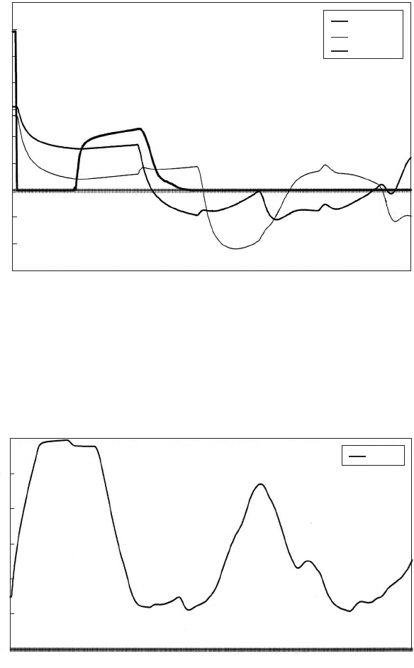
Following simultaneous failure of all four pumps, head at the pumping
station and 7 km along the new rising main declined as shown in Fig. 20.8.
Following the initial downsurge there is an interval of relatively small
head change at the pumping station and then a steady head rise towards
a maximum after flow reversal. Looking at the velocity downstream of the
pumps and at the start of the two mains (Fig. 20.9), it can be seen that
the flow from the pumps stops very quickly after pump trip and the check
valves close. This rapid response is primarily due to the presence of the
pressure vessel. After about 24 s, check valves reopen and velocity
upstream of the pressure vessel reaches almost 1.3 m/s before gradually
declining to zero at around 65 s. A bypass fitted with a check valve
would operate in a similar manner.
The second check valve closure is much more gradual than the first.
Thereafter the check valves were predicted to remain shut. The reason
for reopening of the check valves is because of the low head which has
developed by 23 s after trip (Fig. 20.8). This low head is less than that in
the suction well and this has allowed flow to become re-established
through the pumps. As flow reverses in the new main (Fig. 20.9), this
386
Abu Dhabi Pumping Station No. 5A
Time (s)
Head (mAD)
PS No. 5A
Ch. 7 km
0.327
11.118
21.909
32.700
43.491
54.282
65.073
75.864
86.655
97.446
108.237
119.029
129.820
140.610
151.401
162.192
172.983
183.774
194.565
205.356
216.147
226.937
237.728
248.519
259.310
270.101
280.892
291.683
302.473
313.264
324.055
200
180
160
140
120
100
80
60
40
20
0
Fig. 20.8. Head after pumping failure
Pressure transients in water engineering
causes head at the pumping station to rise, with the result that the flow
through the pumps decelerates and the check valves reclose quietly.
The necessary pressure vessel capacity is reduced by reopening of the
check valves. Figure 20.10 shows air volume expanding quite rapidly
387
Abu Dhabi Pumping Station No. 5A
Time (s)
New main
Old main
PS No. 5A
0.327
5.232
10.137
15.042
19.947
24.852
29.757
34.662
39.567
44.472
49.377
54.282
59.187
64.092
68.997
73.902
78.807
83.712
88.617
93.522
98.427
103.332
108.237
113.142
118.048
122.953
127.858
132.763
137.668
142.572
Velocity (m/s)
3.5
3
2.5
2
1.5
1
0.5
0
–0.5
–1
–1.5
Fig. 20.9. Velocity after pumping failure
Abu Dhabi Pumping Station No. 5A
Time (s)
Vessel
0.327
10.791
21.255
31.719
42.183
52.647
63.111
73.575
84.039
94.503
104.967
115.431
125.896
136.360
146.823
157.287
167.751
178.215
188.679
199.143
209.607
220.070
230.534
240.998
251.462
261.926
272.390
282.854
293.318
303.781
314.245
324.709
60
50
40
30
20
10
0
Air volume (m
3
)
Fig. 20.10. Air volume after pumping failure
Check valve dynamics
after pumps were tripped. When the check valves reopen, only a modest
additional expansion occurs, with air volume reaching a maximum of
60 m
3
. Effectively, the recommencement of flow through the check
valves has replaced the need for further outflow from the pressure
vessel.
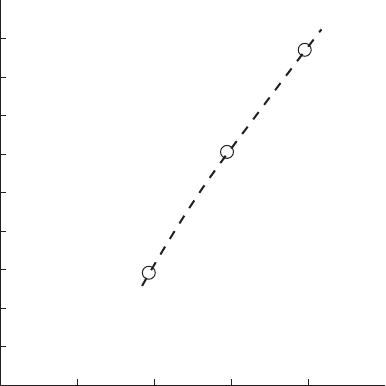
20.6 Check valve response in a multi-pump installation
In a multi-pump installation, maximum upsurge at the check valve is a
function of the number of operating pumps. Figure 20.11 shows one
example of how the maximum transient pressure varies with number
of operating pumps when one of the pumps is tripped.
1 2 3 4
Reversed velocity (m/s)
Number of o
p
eratin
g
p
um
p
s
1 pump tripped and remaining
pumps continue running
1.8
1.6
1.4
1.2
1.0
0.8
0.6
0.4
0.2
Fig. 20.11. Reversed velocity plotted against number of operating pumps
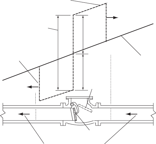
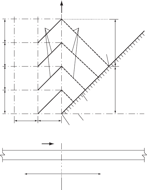
20.7 Surge behaviour as a check valve shuts
Figure 20.12 shows a sketch of transient piezometric level around a
check valve before and just after closure. The sudden head rise down-
stream of the valve following closure is accompanied by a corresponding
head drop upstream of the valve. If head upstream falls below vapour
pressure or gas release head then the minimum head will be determined
by these effects. Notwithstanding this complication, the differential
head across the closed check valve door will impose a longitudinal
388
Pressure transients in water engineering
thrust on pipework. Deceleration of the door itself as it meets its seat
will add to the thrust. The pipe, pump and valve supports should
together be able to transfer this thrust to the foundations of the station
without incurring unacceptable movement. Failure to absorb this force
may result in the pump and valve being pushed out of position and
cracking where the suction branch passes through the sump wall.
Noise and vibration often accompanies check valve closure.
For the situation shown in Fig. 20.12, the differential head across the
check valve produces a hydrodynamic thrust in the upstream direction:
Thrust ¼ 2aAV
o
ð20:1Þ
The time of closure of a free-acting check valve is strongly dependent
upon the response of the system within which it is installed. Not all
computational models will be able to integrate movement of the
check valve with the hydraulic transient analysis in order to establish
times of check valve closure. In carrying out calculations using a
model of this type where a check valve is involved, a time of valve
closure should not be imposed as with an actuated valve. To pre-
select a time of closure without reference to the system response on
389
Transient hydraulic gradient
along failing pump branch
before NRV closure
Reversed velocit
y
before closure
Door closed
V = 0 V = 0
a/gV
o
dx/dt = +a
dx/dt = –a
a/gV
o
V
o
V
o
Door open
Compression wave travelling
downstream after valve closure
Differential head across
valve door after closure
Rarefaction wave travelling
upstream after valve closure
Fig. 20.12. Head conditions when check valve shuts
Check valve dynamics
which check valve closure depends, risks numerical prediction of surge
effects which will not actually occur.
A two-stage process can be used to determine an appropriate valve
type. First the model can be used to simulate pump failure ignoring
the influence of the check valve. This will yield the variation of
dV=dt at the point where the valve is to be placed. Using charts for
individual valve types (see Chapter 21), relating dV=dt to reversed
velocity at the moment of closure, then an appropriate reversed velocity
and closure time can be determined for a candidate valve. The values of
closure time or reversed velocity can now be used in a rerun of the
model to predict transient effects within the system after closure.
Some charts showing valve closure performance as a function of
dV=dt have been included in Chapter 21.
20.8 Modelling a pumping station
The approach to modelling may be dependent on the capabilities of the
computer model available. If the modelling exercise is only one part of an
overall study of hydraulic transients in a system then the computer model
may reasonably be expected to encompass the entire network. As pipe
lengths within a pumping station may be quite short, this implies a
small time increment which may not be particularly suitable for the
much larger pipe lengths appropriate to the majority of the network. A
modified computational scheme using two time step sizes and which
was described in Chapter 6 may be useful in this context. The author
has used this technique on a number of occasions in these circumstances.
If interest is centred on behaviour of the check valve alone and
transient behaviour in the system as a whole does not require to be
modelled then it may be possible to terminate the computer model
local to the pumping station using a non-reflecting boundary, also as
described in Chapter 6. This can be done when it is considered that
the check valve will close in a short time relative to the wave reflection
time from the nearest feature along the pipeline, which will produce a
significant response. In this instance a non-reflecting boundary can be
introduced close to the pumping station.
20.8.1 Non-reflecting boundary with allowance for external pipeline
resistance
The technique as described in Chapter 6 is clearly approximate since
although no effects will return to the boundary from discrete features
390
Pressure transients in water engineering
along the pipeline such as changes of cross-section, bifurcations, valves,
etc. there will be a more gradual and continuous change due to the
action of pipeline resistance. If necessary, some allowance can be
made for this effect by slowly modifying the invariant value from the
external system over time. Allowance for resistance within this external
system can be accommodated in a number of ways.
One approach is illustrated in Fig. 20.13. The sign convention for
þve flow direction uses a code number s ¼1. If þve flow is from
inside the modelled area towards the boundary then s ¼þ1 otherwise
s ¼1. Starting from steady flow conditions at time t ¼ 0, a character-
istic C
s
can be pictured leaving the boundary with initial steady flow
values V
s
and H
s
. As this path propagates into the external system it
defines a boundary between a region of known steady-state conditions
and an area in which potentially conditions of motion are changing with
391
Steady-state region
V = V
s
(constant)
Part of system
being modelled
External network
+s
V
s
, H
s
Steady flow values
C
s
C
o
C
t = 0.0 (start of computation)
Dx
Dt
Dt
Dt
Dt
Dx
T/2
T/2
V
s
, H
T/2
V, H
+t
Fig. 20.13. Non-reflecting boundary with resistance allowance
Check valve dynamics