Ellis,J. Pressure transients in water engineering, A guide to analysis and interpretation of behaviour
Подождите немного. Документ загружается.

372
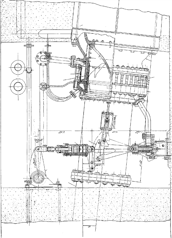
Control shaft
C.l. of spiral casing
Spiral
extension pipe
Dashpot A
Cam C
Connecting pipe
Piston
(closing
member)
Outer
cylinder
Outer cylinder
Dismantling ring
Bridge piece
Control valve B
Inner
body
Fig. 19.15. Cylindrically balanced relief valve
Pressure transients in water engineering
streamlined passage which allows flow to be deflected outwards into a
3 m long ‘hood’ of diameter 1200 mm. Water travels along the hood
in the form of a hollow jet which becomes highly aerated as it exits
from the hood. The valve and hood are angled downwards towards
the tailwater channel at an angle of 98. Energy of the flow is dissipated
by friction between the flowing water and the air and by turbulence
when the flow from the valve enters the tailwater. This downstream
channel had a length of 43 m.
In one application the cylindrically balanced valves were used to
discharge flow passing through a hydropower plant. Operating head
at the plant typically varied in the range 263—274 m depending upon
the number of turbines running. If a machine is shut down its inlet
gates are shut in around 2 s to avoid overspeed. The relief valve for
that turbine is opened in around 3 s to discharge the flow which was
previously passing through the machine. Subsequently, the valve is
closed in a time interval of 70—80 s. At full load, a turbine may consume
almost 20 t of water/s and this flow is diverted through the relief valve
when the turbine is shut down. Exit velocity was 61 m/s.
In common with many hydropower installations around the world,
the turbines were uprated with a consequent increase in the amount
of water passing through the station and during trip, through the
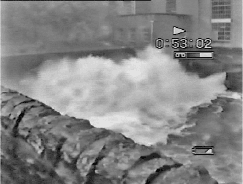
relief valves. Figure 19.16 shows the aerated jet exiting from the
hood and impacting with the tailwater for the uprated situation. At
low tailwater level, part of the aerated flow could be deflected upwards
373
Fig. 19.16. Aerated jet leaving relief valve
Relief valves
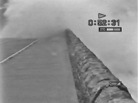
to pass over the parapet of a road bridge (Fig. 19.17). This situation was
not considered acceptable, as one day a tourist bus stopped on the
bridge with its roof vents open. Two turbines tripped and the resulting
relief valves’ operation soaked the passengers, with water flooding out of
the bus when the door was opened. A longer tailwater channel would
have solved the problem but this was not a practical proposition. The
1200 mm diameter outlet hood was modified to include a truncated
cone containing orifices. This caused outflow to break into a large
number of jets and increased aeration and energy dissipation. While
not completely eliminating the problem of water spilling over the
parapet, some improvement has been achieved.
Other options were tried in an effort to reduce severity of the prob-
lem. One attempt adjusted the relief valve movement so that it could
only open to possibly 70%. A test using a partially opened valve setting,
and without any preliminary analysis of likely effects, produced results
described by the operators as ‘horrifying’. The entire power station
vibrated and shuddered, with penstock pressures reaching 500 psig,
which is above design maximum pipeline pressure. The relief valve
was designed to pass flow without large energy loss within the stream-
lined passages. Part-open operation creates conditions for substantial
head loss within the valve itself. Given the overall amount of energy
involved, around 40 MW/machine, any attempt to dissipate flow
energy within the valve through turbulence will inevitably result in
substantial vibration and must be avoided.
374
Fig. 19.17. Spillage over bridge parapet
Pressure transients in water engineering
This example has illustrated that the solution does not just involve
choosing a relief valve but also involves conditions downstream of
the valve to ensure that adequate provision is made for adequate dissi-
pation of energy associated with the outflow and safe disposal of
discharging water. In the present instance, a greater length of tailwater
channel would have avoided the problems experienced.
19.10 Bursting disk
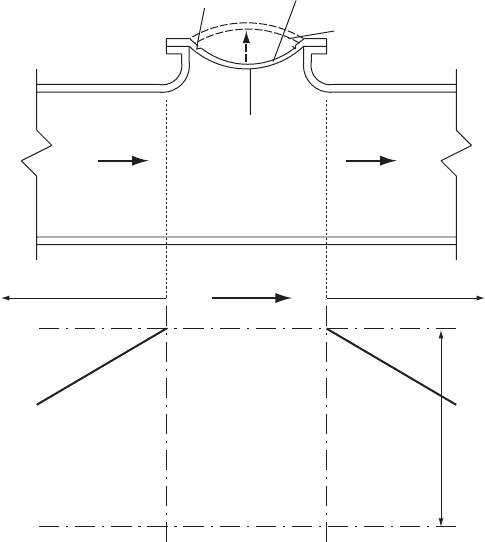
The bursting disk may also be viewed as a form of relief valve (Fig. 19.18).
Should internal pressure exceed the set pressure for operation then the
disk will ‘snap through’ and fail around its notched perimeter, allowing a
free discharge of liquid and thus alleviating rising internal pipeline
pressure. Clearly no means of shutting off the escaping flow is provided
by the failed disk and the system has to be shut down by other means.
This form of protection is relatively uncommon in water and sewage
applications.
375
Circular notch
C+ C–
Busting disk
Initial position
Pipeline
+
V
u/s
V
d/s
Dx Dx
Dt
Snap-through position
Fig. 19.18. Bursting disk
Relief valves
20
Check valve dynamics
Check valves have long been a potential source of unacceptable
pressure transients. Within pumping stations the loud bang associated
with check valve closure has been called ‘slam’. This is indicative of a
valve door or doors not closing sufficiently quickly and allowing flow
to reverse through the valve. Subsequent elimination of this reversed
flow has caused severe pressure transient effects in many installations.
Proper choice of valve can avoid development of these effects. Avoid-
ance in the first instance is much better than attempting to suppress the
effects once they have occurred.
Check valves, also called non-return valves (NRVs) or reflux valves,
are used to prevent reversal of flow. In practice with most valve types,
some flow will usually pass through the valve before it is able to close
completely. It is important to understand how a specific check valve
will response to the reflux conditions within a given pipeline system.
Two facets present themselves with regard to the task of establishing
how a check valve will respond. First there is the question of what
rates of flow change, that is accelerations or decelerations, will occur
in a given network and this aspect is discussed in the current chapter.
The second question relates to how different types and sizes of check
valve will perform within a particular system. This second aspect is
considered in Chapter 21.
20.1 Check valve response
Check valve behaviour has received a great deal of attention over the
years, not only with respect to the valves themselves but also their effect
upon pipeline systems. The relative frequency of starting and stopping of
pumps in sewage transmission systems and the resultant accumulation of
376
pressure oscillations over time has influenced recommendations regarding
allowable amplitudes of pressure transient oscillations for some types of
plastic pipes. A pumping station with a solo duty pump and with a
dischargebranchsizecomparabletothediameterofrisingmainwillbe
more likely to produce higher amplitudes of surging along the main than
a system in which several pumps are operating and which have different
stop levels.
The ability of a check valve door to respond in a way which matches
the changes taking place in the pipeline system is of the utmost impor-
tance. The system will produce a rate of velocity change dV=dt which is
a function of the characteristics of the pipeline network and predicting
this rate of change is a primary objective of transient investigation and
the concern of this chapter.
20.2 Pumping station check valves
One of the most common applications of check valves is within
pumping stations (Fig. 20.1). A check valve is commonly sited down-
stream of each pump within its discharge branch. On occasion, a
larger check valve may also be found at the start of a rising main as
shown in the figure. This valve will provide protection for the pumping
station in the event of a pipe burst within the station. Check valves are
also found in vessel connections where they form a part of throttle
arrangements.
Within a pump discharge branch, as a check valve closes, say following
a pump failure, flow will decelerate at the valve at a rate which is depen-
dent upon a number of factors including, pumping head, flow, pump
characteristics, speed and moment of inertia. The number of pumps in
operation and the presence or otherwise of surge protection equipment
at or near to the pumping station are also important factors.
An ideal check valve would close at the instant of flow reversal but
this perfect performance is not attainable in practice. There will always
be some reverse flow in the system at the time when the valve finally
shuts. Within the same installation, alternative patterns of check
valve will respond in different ways, with the time of valve closure
being a function of the specific valve characteristics.
20.3 Consequences of an unsuitable check valve installation
When a check valve is not suitable for the installation in which it is
placed, serious consequences can result. A graphic illustration of the
377
Check valve dynamics
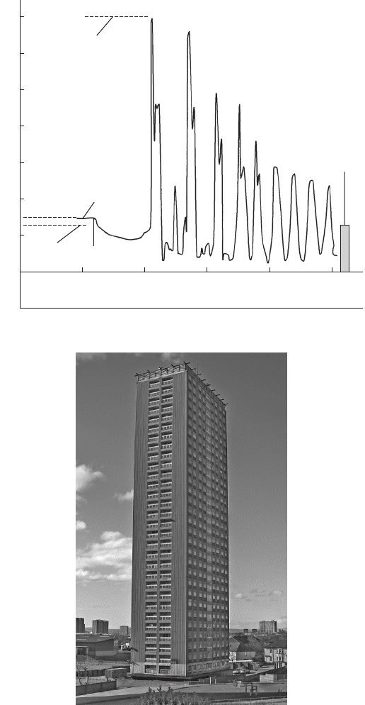
effect resulting from inappropriate check valve selection is shown in
Fig. 20.2 which depicts the transient pressure variations measured
just downstream of the conventional swing check valve of a booster
pump serving a 30-storey apartment block (Fig. 20.3). The local
water undertaking delivered potable water to a storage facility at the
base of the building with a booster pump providing the necessary
pressure to convey water through a DN 100 wet riser to a storage
tank at the top of the structure, a height of 70 m. The pressure
378
Discharge header
Rising main
Isolating valve
Isolating valve
Isolating valve
Suction
branch
Pump
Suction header
Check valve
Check valve
Delivery branch
Pressure vessel
Fig. 20.1. Check valves at a pumping station
Pressure transients in water engineering
379
350
300
250
200
150
100
50
0
–50
Pressure head (mWG)
Recorded pressure transient in
high-rise building following pump trip
Peak pressure
head = 350 mWG
Record from just downstream
of swing check valve
Steady running head
= 78.83 mWG
Static head
= 75 mWG
Pump trip
Time (s)
High-rise building
0 1 2 3 4 5
Fig. 20.2. Recorded pressure variations downstream of a check valve
Fig. 20.3. High-rise building
Check valve dynamics
record shows steady pumping conditions before pump trip and also the
transient pressure head following pumping failure. Total period of the
record was around 5 s. Static pressure head at the check valve was
70 mWG. Steady running pressure head while pumping rose to
78.83 mWG. Subsequent to pump trip, pressure fell to a minimum of
46.61 mWG as flow reversed. Head then started to increase slightly
prior to check valve closure. After closure, transient pressure rose
abruptly to a head of 350 mWG. Elastic oscillations produced further
severe pressure peaks and after 5 s the maximum head still remained
above the height of the building. The high transient pressures caused
burst pipe connections, vibrations and noise, with the result that
occupants had to be evacuated. This is an instance of an unsuitable
check valve selection resulting in delayed valve closure and allowing
development of substantial reversed flow in the system. The remedy
was to install a valve possessing fast-closing attributes or alternatively
to use a valve with a damped closure.
20.4 Prediction of pumping station hydraulic transients
Pressure transient analysis of a complete system seeks to determine the
extreme head and flow changes which occur in the network as whole.
This will involve predicting the effects of simultaneous trip of the
maximum number of operating pumps, as well as other pump combina-
tions, in an endeavour to find maximum rates of velocity change and
peak head variations. Such an analysis would be necessary in the case
of solo pumping for the high-rise building discussed in section 20.3.
In contrast, prediction of reflux within many pumping stations requires
studying trip of one pump while the maximum number of remaining
duty pumps continues to operate. This will usually yield the maximum
rate of flow deceleration within the suction and delivery branches of the
failing pump.
Determination of the suitability of a valve for a particular application
requires consideration of two aspects.
First, prediction of the rate of deceleration and time of flow reversal
at a check valve is a matter for hydraulic transient analysis using the
techniques described in earlier chapters. This requires a model to be
set up of the pumping station and possibly part or all of the pipeline
system. It may not be necessary to model an entire network if interest
is solely in the response of the check valve. A ‘local’ model may allow
prediction of check valve closure in many instances where the closure
occurs within a relatively short time and before the entire pipeline
380
Pressure transients in water engineering
has had a chance to respond. Installations with a pressure vessel or
where several pumps are in operation are cases in which such ‘local’
models may be appropriate.
Second, the response of a particular size and pattern of check
valve, to the predicted rates of change of velocity and time of flow
reversal, requires consideration of the valve characteristics. These
characteristics can include such aspects as weight and inertia of
moving parts, travel distances for valve doors, hydrodynamic force
and/or torque acting on the valve door(s), bearing friction, and external
factors such as spring stiffness or dimensions and weights of external
levers. Some consideration will be given to specific valve types in
Chapter 21.
Some features will tend to produce more severe reflux conditions
than others and Fig. 20.1 displays a pumping station arrangement
which will tend to create a high rate of deceleration along the branch
containing a failing pump. The presence of several operating pumps
and the pressure vessel will all tend to maintain higher pressures in
the discharge manifold than otherwise. Figure 20.4 shows the hydraulic
gradient along the failing pump branch during steady pumping and also
a short time after the pump has tripped. Where there are a number of
operating pumps, the failure of one unit will cause a shift in the
operating point of the remaining pumps. The flow will not fall so
dramatically as if only one pump were in operation.
The presence of a local pressure vessel will provide a further source of
liquid in the event that a pump fails. As pressure tends to fall in the
manifold, the gas charge in the vessel expands causing outflow from
the vessel into the manifold, thus helping to sustain piezometric level
and promoting a steeper adverse hydraulic gradient along the suction
and discharge branches of the failing pump.
With piezometric level declining only slowly in the manifold, a
steep deceleration gradient is created along the branch of the failing
pump as illustrated in Fig. 20.4. As the failing pump decreases in
speed, its ability to maintain flow also decreases. Within a short
time, which can be as little as 0.2 s, the flow has reversed at the
check valve. Ideally the door of the valve should be close to its seat
at the time of flow reversal so that final closure occurs with only a
modest reversed velocity having been established during the final
stages of closure. Steepness of the deceleration gradient is also a func-
tion of the pumping head, with a higher head tending to produce a
more rapid flow deceleration for a given pumping station pipework
configuration.
381
Check valve dynamics