Ellis,J. Pressure transients in water engineering, A guide to analysis and interpretation of behaviour
Подождите немного. Документ загружается.

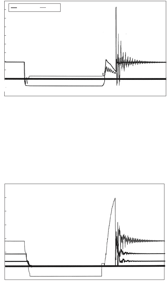
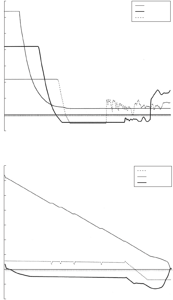
closed and velocities upstream and downstream of the air valve connec-
tion were equalised when an abrupt upsurge developed. Peak head was
around 170 mAOD. Actual measurements indicated that maximum
pressure could reach almost 20 bar(g). The resulting elastic oscillation
decays rapidly over about 1 s. Predicted velocity variations during this
event are shown in Fig. 18.30 for the pump delivery (DN 350), at
the elevated air valve (DN 500) and at the start of the rising main
352
Ayr solo pump op/blockage and restart after 2 s
Delivery Riser
Time (s)
Head (mAOD)
180
160
140
120
100
80
60
40
20
0
–20
–40
0.002
0.134
0.267
0.400
0.532
0.666
0.798
0.931
1.064
1.197
1.330
1.462
1.595
1.728
1.861
1.994
2.126
2.259
2.392
2.525
2.658
2.791
2.923
3.056
3.189
3.322
3.455
3.587
3.720
3.853
3.986
4.119
Fig. 18.29. Head variations due to pump blockage
Ayr solo pump op/blockage and restart
Time (s)
Velocity (m/s)
0.002
0.139
0.277
0.415
0.553
0.691
0.828
0.966
1.104
1.242
1.379
1.517
1.655
1.793
1.931
2.068
2.206
2.344
2.482
2.620
2.757
2.895
3.033
3.171
3.308
3.446
3.584
3.722
3.860
3.997
4.135
3.0
2.5
2.0
1.5
1.0
0.5
0
–0.5
Fig. 18.30. Velocity variations during pump blockage
Pressure transients in water engineering
(DN). Maximum velocity at the pump delivery reached 2.5 m/s.
Changing air volume in the pipeline is shown in Fig. 18.31. After the
blockage, the riser started to drain, air volume increased steadily to a
peak of around 35 litres over the 2 s interval of the blockage. After
the pump started to function, once more the air volume was vented
through the air valve over a time of around 0.2 s.
353
Ayr solo pump op/blockage and restart
Time (s)
Air volume
Air volume (l)
0.002
0.136
0.271
0.405
0.539
0.674
0.808
0.943
1.077
1.212
1.346
1.481
1.615
1.750
1.884
2.019
2.153
2.287
2.422
2.556
2.691
2.825
2.960
3.094
3.229
3.363
3.498
3.632
3.767
3.901
4.036
40
35
30
25
20
15
10
5
0
–5
Fig. 18.31. Air volume in riser during blockage event
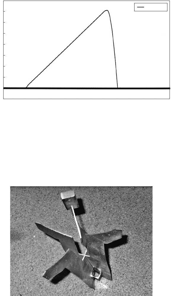
Fig. 18.32. Dama ged air valve components
Air and gas
The peak pressures recorded were sufficient to damage air valves and
pressure transducers. Initially 10 bar(g) rated transducers were installed
and destroyed by the pressure transients. Replacement instruments
were rated to 20 bar(g) and survived. Air valve floats were crushed
and Fig. 18.32 shows the buckled elevator between floats of an APEX
valve typical of the damage caused.
18.9 Pumped outfall pipeline
Common features of many outfall systems are a relatively flat landward
stretch of pipeline followed by a descending seaward section leading to a
diffuser. Quite often the connection between these parts occurs at a
seawall where pipeline elevation increases locally. The relatively low
head under which these schemes operate makes them prone to the
development of sub-atmospheric pressures with the attendant riak of
gas release and formation of vapour cavities.
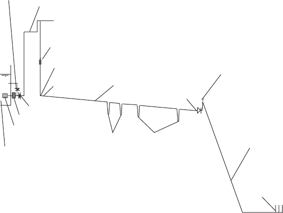
18.9.1 Pipeline configuration
The case considered had some additional features which made develop-
ment of cavities more likely. Figure 18.33 shows a schematic of the
354
Diffuser
DN 450 seaward
steel main
Seawall with tee
for air valve
NRV
Elevated section of 300 mm line
Tied bend
M
Viking Johnson coupling
Duck-foot bend
300 mm valve
Pump
Strainer
Crossings below drainage channels,
water main and main road
Treated effluent lagoon
DN 450 DI
landward main
300 ¥ 450 joint
75 mm recirculation
line with valve
Fig. 18.33. Schematic of pumped outfall
Pressure transients in water engineering
pumped outfall arrangement. Treated chemical effluent is stored within
lagoons at an elevation reaching 8.0 mAD. A strainer is provided at the
intake before flow passes through a Uniglide pump. Discharges through
the outfall are confined to a few hours around high water in the estuary,
and during the times when outflows are not permitted, flow is circulated
through the pump and back to the storage ponds through a 75 mm line
complete with a shutoff valve. Downstream of this 75 mm recirculation
branch connection is a 300 mm valve which controls discharge to the
outfall. The 300 mm welded steel pipeline is carried across the site on
gantries at a level 5.5 m above ground for most of the elevated section
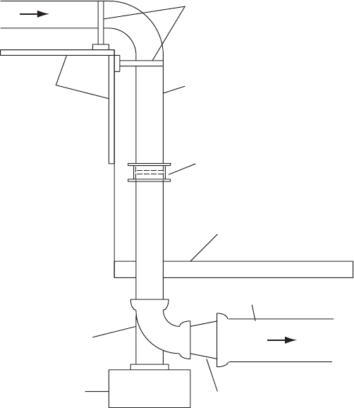
but rising to 6.7 m above ground for a short final stretch. A 908 welded
joint, tied to the gantry using steel straps, is followed by a vertical
300 mm pipe containing a Viking Johnson coupling (Fig. 18.34).
Below this coupling is a 908 duck-foot bend followed by the connection
to the 450 mm landward section of pipeline. This pipeline descends
gradually from an upstream invert level of 5.89 mAD to a minimum
355
300∆ welded steel pipe
450∆ DI pipeline
Steel straps
Pipe support gantry
Concrete footing
300 ND duck-foot bend
Ground level
Viking Johnson coupling
300 ¥ 450 concentric taper
Fig. 18.34. Detail of Viking—Johnson coupl ing
Air and gas
of 4.63 mAD over a length of 3450 m. At four locations along the
landward pipeline the invert falls to pass below drainage channels, a
main road and a water main. A NRV is located at chainage 3450 m.
Tide levels in the estuary can range from a minimum of 6.0 mAD
to a maximum of þ7.45 mAD. The check valve will prevent seawater
entering the landward pipeline at high tide levels. As it passes through
the seawall, pipe level rises by a modest amount to almost 5.5 mAD.
The steel seaward pipeline descends uniformly to 6.87 mAD over a
distance of 735 m and then runs more or less horizontally for a further
732 m to reach the diffuser section.
18.9.2 Viking-Johnson coupling failure
During pump operation following a period of low tide level, the Viking-
Johnson coupling in the vertical 300 mm pipeline failed. Hydraulic
transient studies were carried out in an attempt to establish the cause
of failure.
Initial interest was on conditions within the pipeline prior to pump
start. On completion of the previous pumping cycle the 300 mm
valve was closed and the pump shut down. The result is a downsurge
which produces severe vacuum pressures over most of the system.
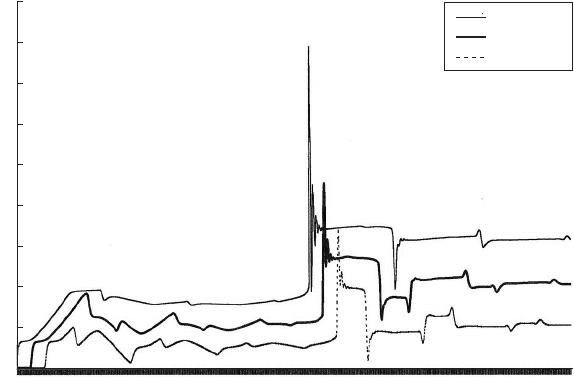
Figure 18.35 shows head variations at the 908 tied bend and at
chainages of 1600 and 3200 m along the landward main over an 8 s
interval. Effectively the downsurge is terminated by the development
of cavities. The modest head rise at chainages 1600 m and 3200 m is
produced on flow reversal assuming the check valve at the seawall
does not close immediately on flow reversal. Figure 18.36 depicts
the envelope curves of maximum and minimum head for this event
over the 4917 m long outfall. If the NRV shuts tightly and prevents
reversed flow into the landward main and the 300 mm valve
downstream of the pump is also closed, a ‘locked-in’ sub-atmospheric
condition will persist. Only if the NRV is not drop tight or if there
are leaks along the main will any pressure relief occur. It appears
likely that at pump restart significant quantities of gas and vapour
will be present over the elevated section of pipeline and also within
the 450 mm landward main.
18.9.3 Hydrodynamic forces
Pipe joints were designed to resist a maximum pressure of 7 bar(g) and
this limit would not be exceeded were pump start to occur with a fully
356
Pressure transients in water engineering
357
Chaina
g
e (m)
Invert level
Max. head
Min. head
Level (mAD)
70
60
50
40
30
20
10
0
–10
–20
Fig. 18.36. Envelope curves along 4.9 km long outfall
Time (s)
Tied joint
Ch –1600 m
Ch –3200 m
70
60
50
40
30
20
10
0
–10
Head (mAD)
Fig. 18.35. Head variations after pump trip over 8 s
Air and gas
primed main. In general, design of a pipe bend would be based upon the
equation:
Resultant thrust ðNÞ¼2gA½h þ V
2
=ð2gÞsinð=2Þð18:4Þ
where is the total angle of turn and h is the pressure head (metres). It
may be necessary to add other forces such as the weight of a water
column in some instances. The pressure head and velocity should be
the maximum occurring during the surge event.
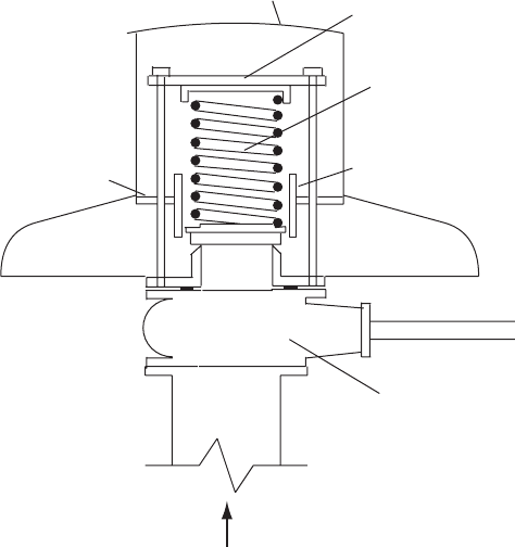
If gas and vapour are present initially then following pump start rising
pressure will cause vapour cavities to collapse, gas to be compressed and
progressively transported and reabsorbed into the flow. Pump start
studies were carried out using a wide range of cavity volumes and
other parameters such as the rate at which gas could be reabsorbed
by the flow. It was found only too easy to create pressures substantially
greater than the 7 bar(g) design limit. Figure 18.37 shows typical time
histories of head at the tied joint and along the main. The most
likely cause of failure was considered to be movement of the 908
bend allowing the upper section of pipe at the Viking-Johnson coupling
to be pulled out. The coupling was designed to accommodate normal
thermal movements of up to possible 10 mm. It would seem likely
that the 908 had been subject to shock pressures above the 7 bar(g)
limit on various occasions when the pump was started, leading to
eventual failure of the coupling.
358
Time
(
s
)
Tied joint
Ch –1600 m
Ch –3200 m
Head (mAD)
180
160
140
120
100
80
60
40
20
0
Fig. 18.37. Head variations following pump restart
Pressure transients in water engineering
19
Relief valves
Just as underpressure can be alleviated through the supply of an additional
source of fluid to a pipeline, so an overpressure condition can be
suppressed by releasing fluid from the network either into an off-line
storage facility or from the system entirely. Compression waves generated
by pump start or by a valve closure can produce acceleration of flow in a
pipeline such that transient pressures exceed the design limit of the pipe-
line. One option for reducing maximum pressures is to have a valve which
opens automatically, discharging a sufficient amount of liquid so that the
downstream pipeline experiences a reduced rate of flow change and a
correspondingly lower surge pressure rise. A variety of pressure relief
devices are available which can be chosen to suit particular requirements.
Pressure relief valves may be attractive to the engineer faced with the
task of reducing waterhammer. Installing a device which automatically
discharges a certain flow when pipeline pressure exceeds its normal
maximum value seems an effective means of protecting the pipeline
against overpressure. If a pressure transient causing a velocity change
V travels along a pipeline of area A, it will produce a head change
a V=g. Releasing a part of the liquid media, usually to atmosphere,
at a rate Q, means that components of the pipeline system will not
be subject to the total change of flow. Instead, the velocity change
will be V—Q=A and the head change a=gðV—Q=AÞ.
To achieve this objective a number of types of relief valve are available
including specialised surge anticipation valves fitted within a pumping station.
19.1 Relief valve types
Relief valves may be installed at any location where there is a risk of
transient pressures exceeding allowable values and may be located for
359
example at a low point on a pipeline where static head is high. Alterna-
tive valve patterns available include spring-loaded types, pilot valve
operated models and instrument operated versions.
Spring-loaded versions are relatively inexpensive and less complicated
than other options. They are usually highly reliable if maintained regularly
and are available in a range of sizes, materials and pressure ratings. The
spring compression is adjustable to create the necessary closure force to
withstand internal pressure up to the set pressure at which the hydro-
dynamic force acting on the valve door element just starts to overcome
the spring force holding the valve door against its seat. A range of springs,
in either carbon or stainless steel, may be provided for each valve to give a
wide range of application. Each of the available springs would normally be
capable of adjustment to cover a range of set pressure.
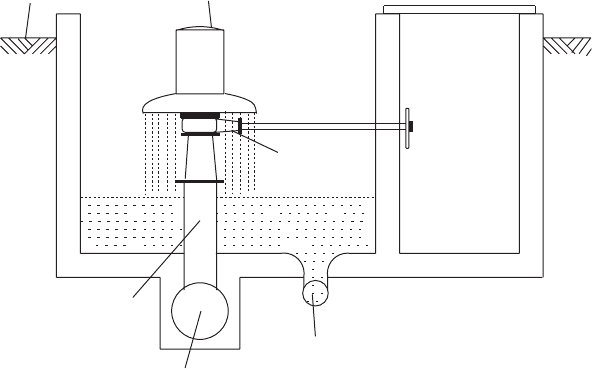
There are many differences between relief valves, and Fig. 19.1
illustrates the main components of a Neyrtec relief valve produced by
Alstom. Figure 19.2 shows a typical installation for a valve of this
type. The valve will be set, usually at the factory, to open when internal
pipeline pressure exceeds an allowable value. This ‘set pressure’ may be
360
Deflector hood
Spring
Stop pieces limiting
lateral travel
Upper plate
Annular plate
Isolating valve
From pipeline
Fig. 19.1. Elements of a relief valve
Pressure transients in water engineering
5% or so higher than the maximum normal operating pressure. As
pressure rises, the valve should open fully.
Valves should operate quietly with no oscillation or hammering. It is
important that the discharge capacity of the valve is not too large for
the application. If the discharge through the valve is insufficient to
keep the valve fully open then hammering and oscillation can occur.
Noises including ‘chatter’ and ‘squeal’ have been reported when a
relief valve is oscillating. Some valves will only open completely with
a pressure 10—25% higher than the set pressure and this may be seen
as a disadvantage.
The possibility of resonant behaviour of relief valves has been the
subject of investigations over the years and manufacturers have
developed valves which seek to eliminate this risk through use of
damping mechanisms or other means such as a hydraulic shock absorber
or accumulator positioned in parallel nearby, which alters the response
of the pipeline.
Figure 19.3 shows a relief valve fitted with a spring but also having a
piston and oil-filled cylinder included. The cylinder is connected at top
and bottom to an oil reservoir which is part-filled with oil. The lower
connection includes a regulating valve which allows oil to flow from the
cylinder to the oil reservoir at a controlled rate. All other flows between
the cylinder and the reservoir occur without restriction. When pipeline
pressure exceeds set pressure, the valve opens quickly, allowing pressure
361
Ground level
Pressure relief valve
Isolating
valve
Outflow
Pi
p
eline
Connection
Fig. 19.2. Simple relief valve installation
Relief valves