Ellis,J. Pressure transients in water engineering, A guide to analysis and interpretation of behaviour
Подождите немного. Документ загружается.

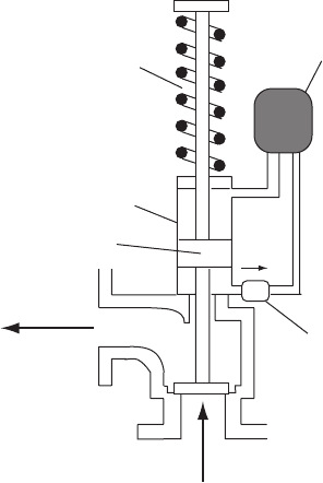
relief to occur. As the valve starts to close, the restricted outflow of oil
from the lower part of the cylinder only permits a slow closure. This
damping effect also eliminates any risk of resonance developing.
Where damping is not included in the valve then it is necessary for
the period of oscillation of the valve’s spring/mass system to be much
less than that of the pipeline in order to avoid occurrence of pressure
pulsations. The moving parts should be as light as possible to reduce
inertia and ensure freedom of movement. Lightness is also favourable
for stable operation.
19.2 Initial valve sizing
Preliminary sizing of a relief valve will normally be confirmed by
computer investigation of hydraulic transient behaviour. The valve
should be sized to operate fully open.
The discharge through the valve might be based on the following
initial value for a change in flow Q:
If the time of flow change is ¼ n2L=a then valve discharge should
be set ¼ Q=n, where a is acoustic wavespeed and L is pipeline
length from source of transient to the relief valve.
362
Spring
Cylinder
Oil reservoir
Piston
Valve giving control on outflo
w
from lower side of cylinder
Discharge to
wet well
From pipeline
Fig. 19.3. ‘Damped’ relief valve
Pressure transients in water engineering
The connection from the main to the relief valve should be as short as
possible to reduce any risk of resonance and to minimise head loss.
19.3 Valve positioning
As well as being found at pumping stations and on pressure vessels, relief
valves can be installed at critical locations along a pipeline and these may
be relatively remote. As with air valves, inspection, maintenance and
reliability are important. Where moving parts have to be guided there is
always the possibility that a valve will seize if elements become jammed
or encrusted with deposits. After some months of normal operation a
safety valve may not operate as intended should a waterhammer incident
occur. The factor of safety which was supposed to exist, based on analysis,
may only be an illusion under these conditions. Then what should have
been an incident may well become an accident. Valves should as far as
possible be tamperproof and provided with padlocks.
19.4 Analysis of behaviour
When a transient pressure rise arrives at the valve connection, the
valve will remain shut until pressure force from within the pipeline
363
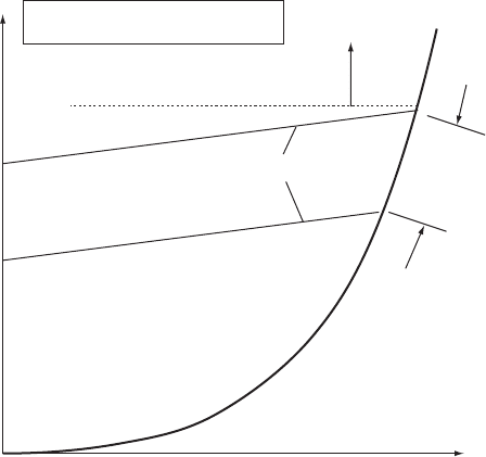
Pressure head (m)
Dischar
g
e (l/s)
H
max
H
max
= maximum set pressure head
H
min
= minimum set pressure head
H
min
Spring coils touching
Parabolic curve
Essentially straight line relationship
Fig. 19.4. Head plotted against flow relationship for relief valve
Relief valves
exceeds that force exerted by the compressed spring. When the valve
opens fully (Fig. 19.4), outflow Q
r
is given by:
Q
r
¼ constant
2
p
ðH zÞð19:1Þ
where Q
r
is discharge through the relief valve, is valve diameter, H is
head at the valve connection and z is the valve elevation. Also the
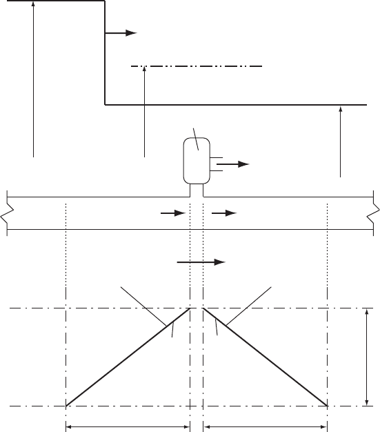
upstream and downstream characteristics (Fig. 19.5) yield the following
equations for the quasi-invariants:
V
u=s
þ g=aH ¼ Jþ and V
d=s
g=aH ¼ J
From conservation of volume:
V
u=s
¼ V
d=s
þ Q
r
=A
364
Wavefront
+
Relief valve
C+
J+ = V
u/s
+ g/aH
u/s
J– = V
d/s
– g/aH
d/s
Dx
Dt
Dx
C–
H
u/s
H
set
H
max
Q
r
V
d/s
V
u/s
Fig. 19.5. Schematic for relief valve analysis
Pressure transients in water engineering
A being pipe cross-sectional area. Eliminating V
u=s
and V
d=s
,
JþJ2g=aH constant
2
=A
p
ðH zÞ¼0 ð19:2Þ
Equation 19.2 can be solved for H and by substituting in the equations
for the quasi-invariants V
u=s
and V
d=s
are found.
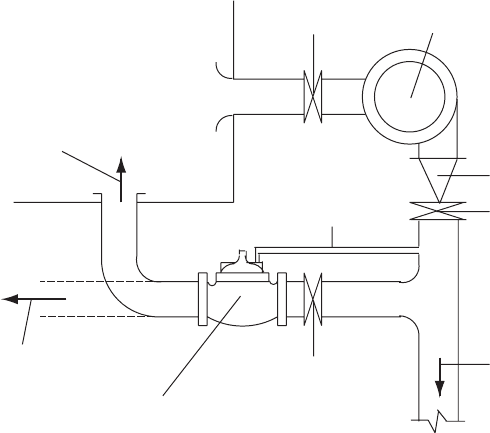
19.5 Automatic surge control valve
This valve is pilot valve operated and Fig. 19.6 shows a possible
installation downstream of pumps. When pumping, the valve remains
shut. After pump trip, piezometric level downstream of the pumping
station falls and the pressure wave propagates along the main, reducing
pressure. Using a pressure sensing tapping, the pressure sensing valve
starts to open at some stage when pressure downstream of the
pump(s) has fallen below the normal minimum operating pressure.
The valve should not start to open until pressure has fallen substantially
and till velocity is small or about to reverse. If the valve is opened while
pressure and flow are still appreciable then the open valve will allow
flow to pass through the valve and allow pressure to fall more sharply
than otherwise. Once flow has reversed and pressure starts to rise
at the pumping station, the open valve allows flow to discharge to
atmosphere or possibly back into a wet well. If maximum reversed
365
Wet well
To wet well
Isolating valve
Isolating valve
Pump
Check valve
Isolating valve
To rising main
Pressure sensing line
To atmosphere
Pilot operated pressure sensing valve
Fig. 19.6. Pressure sensing valve arrangement
Relief valves
flow is represented by a negative velocity V
o
, then without the valve
arrangement maximum head rise will be aV
o
=g as flow is brought to
rest against the closed pump check valve.
With the valve open, flow will continue in the reversed direction
until the valve is closed. When the valve is set to close at a controlled
rate, deceleration of the reversed flow is gradual, thus limiting jdV=dtj
and avoiding further significant transient effects.
It will be noted that this special valve does not alleviate the initial
pressure transient or any low pressures associated with this first down-
surge and only acts to limit maximum pressures following flow reversal.
19.6 Surge anticipation valve
This is similar in operation to the automatic surge control valve but may
also open should maximum pressure exceed the normal maximum oper-
ating pressure by a preset amount. Determination of the appropriate size
of valve or valves to be used and the necessary settings is best done in
collaboration with the valve manufacturer as choice of valve size has to
be quite accurate.
19.7 Pumping station pressure relief valve
A case study involving possible use of a pressure relief valve at a pumping
station concerned a pipeline forming part of the potable water distribution
network for the State of Kuwait. A DN 800 DI rising main conveys water
from Az Zour Desalination plant to Wafra storage complex, a distance of
almost 37 km. Steady pumping pressure at Az Zour reaches 22.4 bar(g)
with the maximum allowable transient pipeline pressure being
27.5 bar(g). The pipeline is fitted with a number of Vent-o-matic air
valves which allow a relatively large air inflow while restricting the air
outflow rate. Steady pumping flow could reach 850 litres/s.
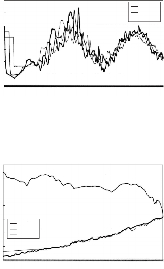
Simultaneous trip of two duty pumps at Az Zour produced the varia-
tions of head shown in Fig. 19.7, at the pumping station, at chainage
10 km and at chainage 20 km. Maximum pressure at Az Zour reached
30 bar(g). The irregular nature of head variation shown in Fig. 19.7 is
largely due to the closure of the large number of air valves which
operated during the initial downsurge which followed pumping failure.
Air valves downstream of chainage 10 km were predicted to operate.
Figure 19.8 shows the envelope curves of maximum and minimum
head along the rising main, with peak pressure remaining above
27.5 bar(g) over the first 2.3 km of main.
366
Pressure transients in water engineering
367
0.112
11.088
22.064
33.040
44.016
54.992
65.968
76.944
87.920
98.896
109.872
120.848
131.823
142.799
153.775
164.751
175.727
186.703
197.679
208.655
219.631
230.607
241.583
252.559
263.535
274.511
285.487
296.463
307.439
318.415
329.391
Head (mPWD)
Time (s)
d/s pmps
Ch. 10 km
Ch. 20 km
Az Zour to Wafra rising main/trip of two pumps/Vent-o-matics
350
300
250
200
150
100
50
0
Fig. 19.7. Head variations following pump trip on a long main
il (mPWD)
h
max
h
min
0
1153.36
2367.56
3532.11
4751.58
5983.65
7155.67
8448.01
9605.88
10823.28
11979.81
13198.89
14418.39
15634.59
16858.59
18029.24
19328.61
20559.99
21843.30
23005.95
24300.18
25532.26
26754.46
28037.77
29262.87
30552.27
31841.67
33075.07
34372.03
35607.23
Elevation (mPWD)
Chaina
g
e (m)
Az Zour to Wafra rising main. Vent-o-matic air valves installed.
Simultaneous trip of two pumps
350
300
250
200
150
100
50
0
Fig. 19.8. Envelope curves following pump trip
Relief valves
368
Head (mPWD)
Time (s)
d/s pmps
Ch. 10 km
Ch. 20 km
Az Zour to Wafra rising main. Vent-o-matic air valves installed.
Simultaneous trip to two pumps. Relief valve at PS
300
250
200
150
100
50
0
0.112
11.872
23.632
35.392
47.152
58.912
70.672
82.432
94.192
105.952
117.712
129.471
141.231
152.991
164.751
176.511
188.271
200.031
211.791
223.551
235.311
247.071
258.831
270.591
282.351
294.111
305.871
317.631
329.391
341.151
352.911
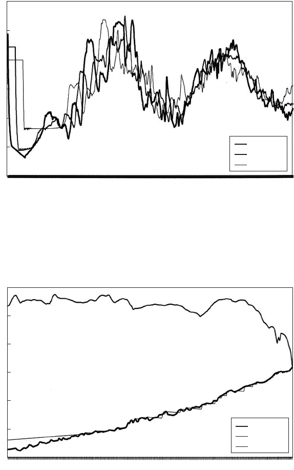
Fig. 19.9. Head variations following pump trip with pumping station relief valve
il (mPWD)
h
max
h
min
Elevation (mPWD)
Chaina
g
e
(
m
)
Az Zour to Wafra rising main. Vent-o-matic air valves installed.
Simultaneous trip of two pumps. Pressure relief valve at the PS
300
250
200
150
100
50
0
0
1153.36
2367.56
3532.11
4751.58
5983.65
7155.67
8448.01
9605.88
10823.28
11979.81
13198.89
14418.39
15634.59
16858.59
18029.24
19328.61
20559.99
21843.30
23005.95
24300.18
25532.26
26754.46
28037.77
29262.87
30552.27
31841.67
33075.07
34372.03
35607.23
Fig. 19.10. Envelope curves following pump trip with relief valve
Pressure transients in water engineering
A pressure relief valve was included at the pumping station as a
possible option to reduce peak pressures. Simultaneous trip of two
pumps was again simulated and Fig. 19.9 shows the resulting variations
of head at the pumping station, at chainage 10 km and at chainage
20 km. The initial fall in head is the same as before but the head rise
after flow reversal only produces a peak pressure of 24.8 bar(g) at Az
Zour. The envelope curves of Fig. 19.10 show reduced maximum
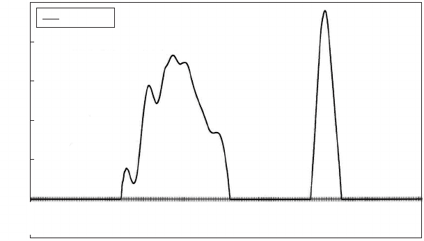
pressures over about the first 15 km of main. Figure 19.11 shows the
predicted outflow through the relief valve. Two periods of operation
occurred, with the first covering an interval of 13 s and having a
maximum discharge of around 180 litres/s, while the second outflow
peaked at about 240 litres/s and had an operating time of about 4.5 s.
19.8 Grove regulator
A variation on the pressure relief valve is a regulator which employs a
rubber sleeve (Fig. 19.12). The regulator comprises a slotted core with a
central barrier. A flexible tube is fitted around the core, covering both
inlet and outlet slots. Surrounding the tube is an annular jacket space
filled with pressurised gas, usually nitrogen. When the annulus between
the outer jacket and the inner slotted cylinder is pressurised to a set
value then the rubber sleeve is pushed against the slotted cylinder,
creating an effective seal. Only when pipeline pressure exceeds the
369
Discharge
Discharge (l/s)
Time (s)
Az Zour to Wafra rising main. Vent-o-matic air valves installed.
Simultaneous trip to two pumps. Pressure relief valve at PS
250
200
150
100
50
0
–50
123.088
124.544
126.000
127.455
128.911
130.367
131.823
133.279
134.735
136.191
137.647
139.103
140.559
142.015
143.471
144.927
146.383
147.839
149.295
150.751
152.207
153.663
155.119
156.575
158.031
159.487
160.943
162.399
163.855
165.311
166.767
Fig. 19.11. Discharge through relief valve
Relief valves
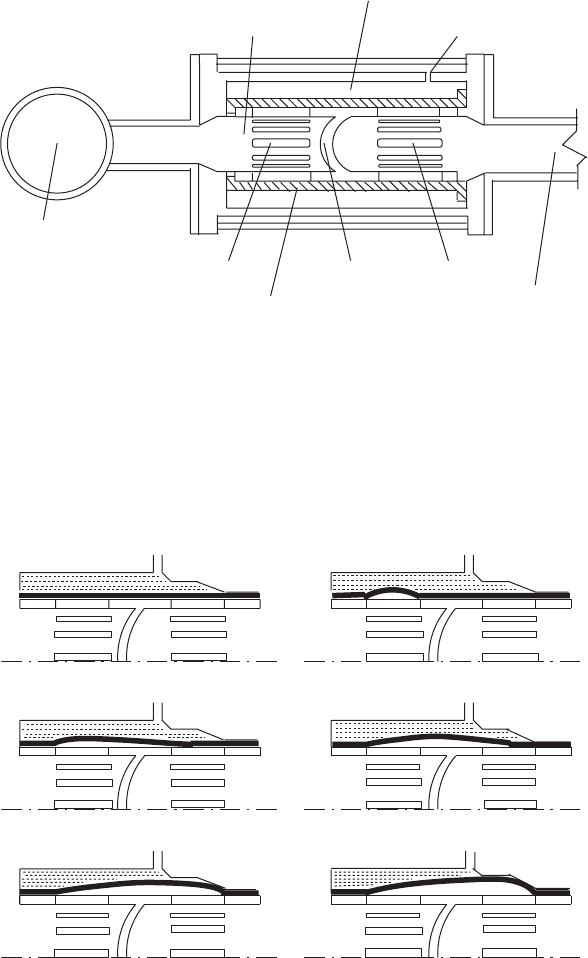
set pressure imposed by the pressurised annulus, is the liquid within the
system able to push the rubber sleeve aside, allowing flow to pass
through the slotted openings from the upstream to the downstream
side of the cylinder. In this way the internal pressure in the pipeline
can be limited in the same manner as achieved by the more common
pressure relief valve. Figure 19.13 depicts the sequence of operation
370
Pressurised nitrogen-filled annulus
surrounding rubber tube
Slotted core
Tapping
Pipeline
Inlet slots Outlet slotsCore barrier
To discharge
Rubber tube
Fig. 19.12. ‘Grove’-type regulator
(
a
)
Closed
(
b
)
Tube startin
g
to lift
(
c
)
Startin
g
to throttle
(
d
)
Throttlin
g
(
e
)
Throttlin
g(
f
)
Throttle wide o
p
en
Fig. 19.13. Operational sequence of regulator
Pressure transients in water engineering
of the regulator. Advantages are its quiet rapid operation and positive
shutoff, even if foreign matter should become trapped between the
core and the tube. There is no risk of oscillation because of the
design of the regulator and the absence of any spring-mass system.
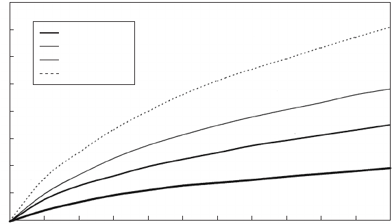
Discharge Q
r
through a regulator can be established using the
formula:
Q
r
¼ Fg
p
P
s
ð19:3Þ
where Fg is a flow factor and P
s
is the set pressure at which the regulator
is set to start opening. Valves of flow factor as a function of percentage
rise above the set pressure are shown for one model of Grove regulator
in Fig. 19.14.
19.9 High head relief valves
Some installations require a relief valve capacity much greater than
that achievable using the types of valve already described. Systems
requiring large relief valve flow rate include high dams and hydro-
power facilities.
One example of a high-performance relief valve is shown in Fig.
19.15. This valve, supplied to a number of hydroelectric installations
by English Electric Company, is of a cylindrically balanced double-
acting pattern. In the example shown, flow enters the valve through
a 710 mm diameter inlet pipe. When fully open, the valve provides a
371
Surge reliever flow factors (F
g
)
1600
1400
1200
1000
800
600
400
200
0
%
(p
ressure rise/set
p
ressure
)
Grove Model 887 surge reliever/low and medium pressures
6 in. (150 mm)
8 in. (200 mm)
10 in. (250 mm)
12 in. (305 mm)
Flow factor (F
g
)
0 5 10 15 20 25 30 35 40 45 50 55
Fig. 19.14. Flow characteristics of regulator
Relief valves