Ellis,J. Pressure transients in water engineering, A guide to analysis and interpretation of behaviour
Подождите немного. Документ загружается.

relatively high adverse gradients along the pipeline after a pumping
failure. Such gradients may lead to high upsurge pressures as the
reversed flow is developed.
When a pressure vessel is to be refilled by the reversed flow, then
introducing a check valve or valves along the main prevents refilling
of the vessel to the extent which would be imposed by the full static
head. This may mean that the need for throttling in the vessel con-
nection is reduced or removed entirely. If no bypass is included at the
in-line check valve, then the vessel gas volume will remain close to
the maximum expanded volume and will not refill.
Choosing a check valve for this application may not necessarily
require a fast-closing performance. Depending upon the size of main,
a swing-check valve or a split-disk pattern with light springs may be
used. A valve pattern involving a sliding movement of the door
under the action of an axial spring has also been applied. The use of
check valves in this type of application should arrange for the valve
to open fully to avoid risk of ‘chattering’. The extra head loss associated
with the in-line application of the valve(s) should also be considered
when compiling system curves and selecting pumps. It may be necessary
for an in-line check valve to be in parallel with an isolating valve of
similar diameter to allow the check valve to be removed for periodic
maintenance.
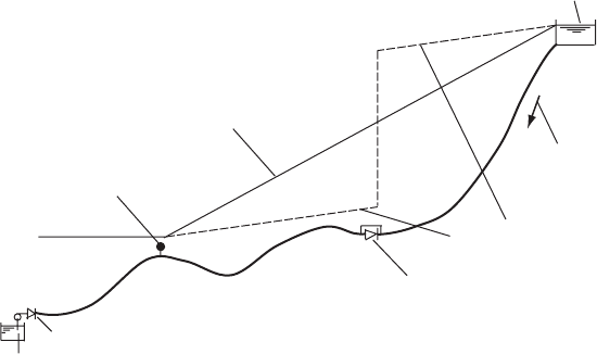
Consider the case of the raw water transfer system from the River
Nile at Gizara to 6th October City. The pumping system is in two
parts. The first stage involves an intake and pumping station on the
River Nile at El Dahab. Discharge is into a DN 1500 DI main of
length 16.5 km. Flow from the main enters storage tanks before being
pumped onwards by the booster pumping station which is the start of
the second stage of the project. Flow then travels a further distance
of 10.25 km through twin DN 1000 DI mains to the treatment works
serving 6th October City. Design flow rate is 2400 litres/s with three
duty pumps in service at El Dahab.
The first-stage pipeline commences at an elevation of þ15 mASL
and runs at relatively low level for 9 km before climbing steeply for
around 3 km to reach a general elevation of þ100 mASL. Thereafter
the line crosses a plateau at a level of þ90 mASL to þ100 mASL
before reaching storage facilities at the booster station. The line is
fitted with three NRVs at chainages 8850 m, 9750 m and 10700 m.
These NRVs are of the torsional spring-assisted closure, split-disk type.
A pressure vessel was included at the pumping station with a steady
pumping air volume of around 20 m
3
. In predicting pressure transient
402
Pressure transients in water engineering
behaviour in the entire system, simultaneous failure of three duty
pumps was examined with pipeline resistance at its minimum assessed
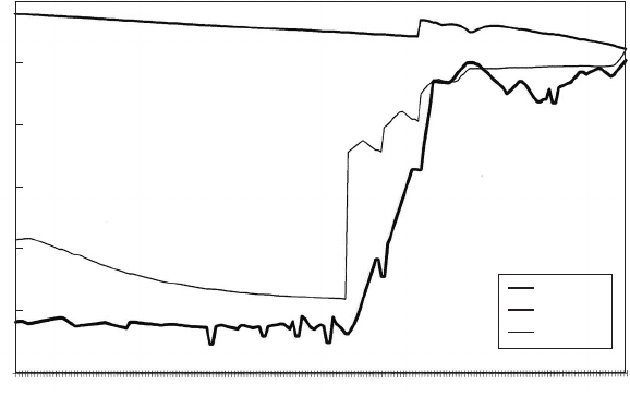
value. Figure 20.19 depicts envelope curves for this event. Minimum
hydraulic level falls relatively smoothly until the first NRV where
there is an abrupt head rise of around 50 m. Thereafter more modest
upward steps in minimum head occur at the second and third NRVs.
Maximum head falls slowly over the upstream 10.7 km and then
there is a modest step rise across the third NRV.
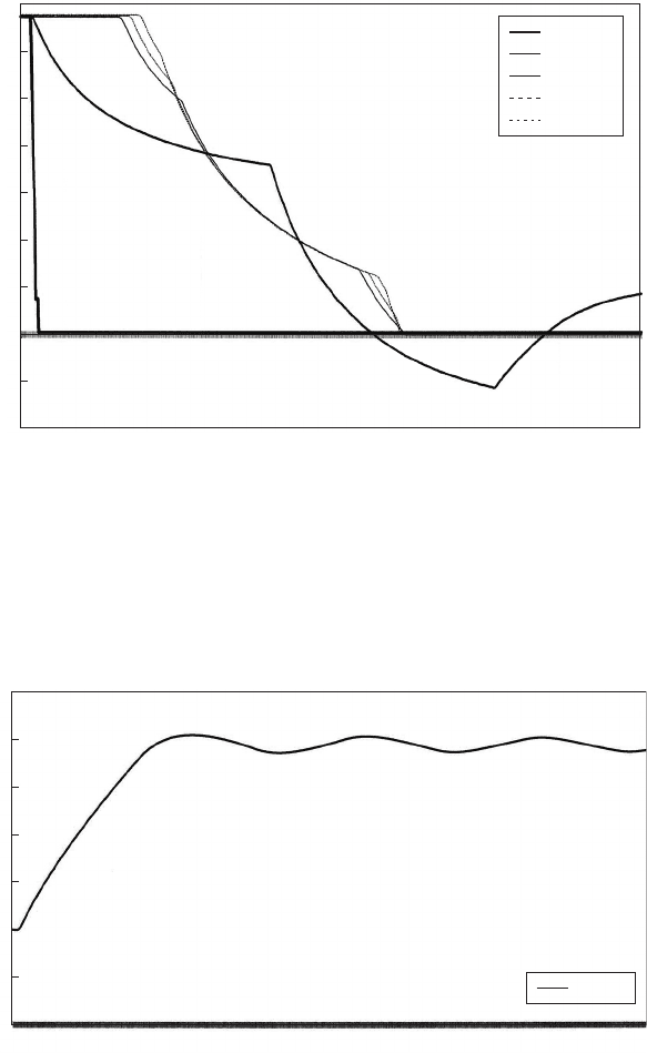
Looking at the predicted velocity variations at the pumping station
downstream of the vessel and at the three NRVs (Fig. 20.20), it can
be seen that flow reversal and check valve closure at the pumping
station occurs very shortly after trip at 1 s. Downstream of the pressure
vessel a much more modest deceleration takes place with flow reversal
after 34 s. Deceleration at the check valves has the same form as
downstream of the vessel and the valves shut after about 37 s with
only a small time difference between valve closure times. The curves
of Fig. 20.20 are important in providing an accurate assessment of
deceleration rates at these valves, thus allowing an appropriate type
of valve to be chosen. In this case the rates of flow change are such
that a high closure performance is not required.
403
0
575.6
1247.1
1726.7
2398.3
3069.8
3645.3
4316.9
4892.4
5468.0
6043.6
6619.2
7098.8
7578.5
8154.1
8633.7
9209.3
9784.9
10 360.5
10 840.1
11 415.7
12 087.2
12 662.8
13 334.3
13 909.9
14 389.5
14 965.1
15 540.7
16 212.2
Chaina
g
e (m)
i.l. mASL
h
max
h
min
Gizera/El Dahab pumping station and DN 1500 rising main
Elevation (mASL)
120
100
80
60
40
20
0
Fig. 20.19. Envelope curves after pumping failure
Check valve dynamics
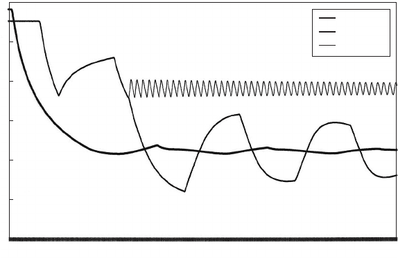
Closure of the first NRV largely deprives the pressure vessel of
refilling water and Fig. 20.21 shows that after the air volume expands
following pumping failure there is only a small reversed flow and the
volume oscillates around an eventual steady volume of almost 60 m
3
.
404
0.093
2.139
4.185
6.231
8.277
10.323
12.369
14.415
16.461
18.507
20.553
22.599
24.645
26.691
28.737
30.783
32.829
34.875
36.921
38.967
41.013
43.059
45.105
47.151
49.197
51.243
53.289
55.335
57.381
59.427
PS
d/s vessel
u/s 1 NRV
u/s 2 NRV
u/s 3 NRV
Gizera/El Dahab pumping station and DN 1500 rising main
Time (s)
Velocity (m/s)
1.4
1.2
1
0.8
0.6
0.4
0.2
0
–0.2
–0.4
Fig. 20.20. Velocity changes after pumping failure
0.093
3.906
7.719
11.532
15.345
19.158
22.971
26.784
30.597
34.410
38.223
42.036
45.849
49.662
53.475
57.288
61.101
64.914
68.727
72.540
76.353
80.166
83.979
87.792
91.605
95.418
99.231
103.045
106.858
110.671
114.484
118.297
Vessel
Gizera/El Dahab pumping station and DN 1500 rising main
Time (s)
Air volume (m
3
)
70
60
50
40
30
20
10
0
Fig. 20.21. Vessel air charge after pumping failure
Pressure transients in water engineering
When pumps are restarted they will commence operation against a low
static head and with the start-up compression wave being reflected from
the first closed check valve.
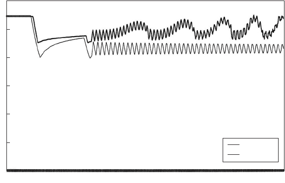
Figure 20.22 shows the predicted head variations at the pumping
station also upstream and downstream of the first NRV, after pumps
are tripped. A smooth fall in head at the pumping station is followed
by a very modest oscillation around an eventual static head of about
45 mASL. Upstream of the first NRV the head drop initially follows
the same form as at the pumping station until a wave reflection from
downstream produces a head rise beginning after about 14 s. A
second reflection causes head to fall once more and at around 37 s
the NRV shuts. The rate of head drop increases upstream of the
valve after closure and head falls to a minimum at about 58 s.
Thereafter an oscillation occurs between the pumping station and
the NRV, with maximum amplitude at the closed valve. Downstream
of the NRV, head conditions are essentially the same as upstream.
After closure a modest high-frequency oscillation occurs in that section
of main between the now closed first and second NRVs.
Figure 20.23 depicts changing head downstream of the second and
third NRVs. After closure of the check valves a modest high-frequency
oscillation is developed between the shut second and third valves.
405
0.093
4.092
8.091
12.090
16.089
20.088
24.087
28.086
32.085
36.084
40.083
44.082
48.081
52.080
56.079
60.078
64.077
68.076
72.075
76.074
80.073
84.072
88.071
92.070
96.069
100.068
104.068
108.067
112.066
116.065
120.064
Gizera/El Dahab pumping station and DN 1500 rising main
Time (s)
Head (mASL)
Gizera
u/s 1 NRV
d/s 1 NRV
120
100
80
60
40
20
0
Fig. 20.22. Head variations after pumping failure, upstream part of system
Check valve dynamics
Downstream of the final NRV the oscillation is complicated by fluc-
tuations resulting from action of air valves along the final 4.5 km of
main. Positioning of the in-line check valves should seek to avoid the
possibility of vacuum pressures developing at the upstream side of the
valve following closure against a reversing flow. Valves should be
located at points on the pipeline of sufficiently low elevation to
prevent this from occurring.
20.11.5 Inclusion of air valves with in-line check valve
If the pipeline is fitted with air valves which function during the
downsurge allowing air inflow, or if a pressure vessel is installed at the
pumping station, then as flow comes to rest and starts to reverse, air
volumes will exist in the pipeline together with appreciable adverse
hydraulic gradient.
Often air valves are purchased before pressure transient analysis has
been undertaken. Where these valves are of a typical large-orifice type,
giving large inflow and outflow capacity, then a steep adverse hydraulic
gradient will potentially produce high reversed velocity and substantial
abrupt head rise at the valve when it shuts, as described in Chapter 17.
Where the opportunity exists to change the valves then restricted
406
0.093
4.092
8.091
12.090
16.089
20.088
24.087
28.086
32.085
36.084
40.083
44.082
48.081
52.080
56.079
60.078
64.077
68.076
72.075
76.074
80.073
84.072
88.071
92.070
96.069
100.068
104.068
108.067
112.066
116.065
120.064
Gizera/El Dahab pumping station and DN 1500 rising main
Time (s)
Head (mASL)
d/s 2 NRV
d/s 3 NRV
120
100
80
60
40
20
0
Fig. 20.23. Head variations after pu mping failure, downstream part of system
Pressure transients in water engineering
outflow valves may be used to prevent unacceptable secondary tran-
sient effects developing when the valves close. The general principle
is to flatten the adverse hydraulic gradient to remove at least part of
the driving force causing reversed flow.
Where standard large-orifice valves, without outflow throttling, are
used then a check valve or valves can be installed at appropriate loca-
tions along the main. Then reversed flow can be avoided entirely or if a
throttled bypass is provided around the check valve, additional head
loss can be introduced (Fig. 20.24). Allowing some flow through the
bypass dissipates energy and provides an alternative means of flattening
the adverse hydraulic gradient. The extent of throttling controls the
magnitude of reversed velocity so that air valves can close without
severe secondary transient effects developing. Siting of the check
valve has to be at an elevation such that sub-atmospheric pressures
are avoided upstream of the valve.
20.11.6 Backflow check valve
Figure 16.3 shows the pipeline arrangement at a downstream receiving
reservoir which allows reversed flow out of the reservoir. The outflow
pipeline contains a check valve to ensure that flow entering the reser-
voir does so through the normal filling connection. This backflow
arrangement allows water to enter the upstream pipeline in the event
of flow reversal such as might be required to refill a pressure vessel or
407
Downstream
reservoir
Reversed flo
w
Piezometric gradient
without in-line NRV
Double-orifice air valve
Piezometric gradient
with in-line NRV
In-line NRV with bypass
Closed NRV
PS
Rising main
Fig. 20.24. Hydraulic gradients with in-line check valve and bypass
Check valve dynamics
to permit purging of air through air valves. Without this arrangement
the filling connection would empty and possibly a section of pipeline.
This would reduce piezometric level possibly below prevailing ground-
water levels. It will be noted that this back flow arrangement will
have no influence upon transient events until reversed flow has
occurred. There is generally no particular requirement for this check
valve to open rapidly or to close quickly.
408
Pressure transients in water engineering
21
Check valve characteristics
Control of pressure transients is essentially a matter of limiting rates of
velocity change. In the context of check valves, the velocity in question
is the reversed velocity in the pipeline as the valve closure element
approaches its seat. To limit severity of pressures on valve closure,
two principal alternatives are available. First, measures can be taken
to minimise the velocity at the time when the valve closes. This is
achieved by selecting a check valve which has the ability to shut quickly
so that a strong reversed velocity does not have time to develop.
Assumed maximum head rise on valve closure ja=gVj is thus kept
within acceptable limits. An alternative approach is to influence the
way in which the valve door moves, specifically by slowing door move-
ment over all or possibly during the final stages of movement. Reversed
flow is allowed to develop and the door movement is controlled by some
form of ‘damping’ mechanism to prolong closure time. As the door
slowly closes, reversed flow which has developed is then gradually
reduced, yielding a modest deceleration dV=dt and a corresponding
quiet closure.
21.1 Check valve response
Discussions in Chapter 20 relate largely to free-acting valve behaviour.
System response was represented by the rate of deceleration of flow
jdV=dtj and the corresponding variations of pressure at the check
valve. Equal consideration must be given to the ability of check
valves to close in an acceptable manner at a particular rate of flow
deceleration. Not all valves yield the same response. To illustrate this
point Fig. 21.1 shows measured transient pressure just downstream of
the check valve, for three different free-acting valves placed within
409
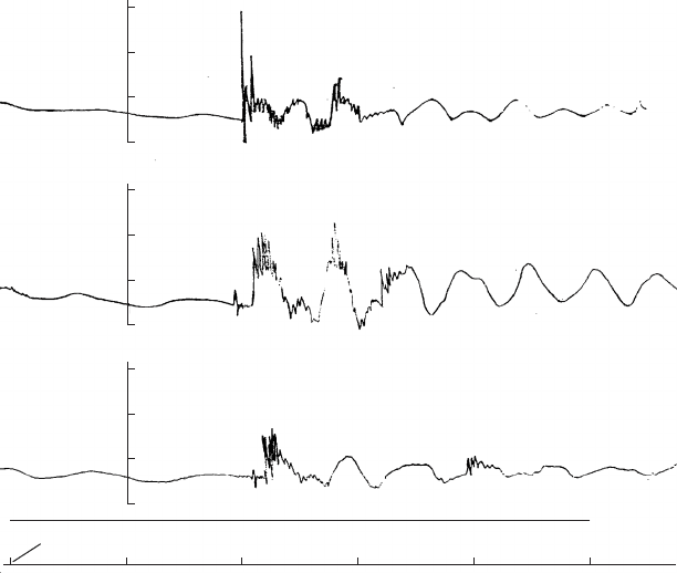
the same reflux environment at Barepot pumping station. In each case
the duty pump was tripped under the same flow conditions. Reflux
valves which will close silently can be produced without difficulty.
The same valve cannot always be guaranteed to offer minimum
resistance to flow and the two factors are largely incompatible.
To discover why valves respond in different ways in a particular situa-
tion, consideration has to be given to the valve characteristics which
affect movement of the closure element(s). The following sections
examine a range of valve types.
While interest is predominantly centred on check valve closure, it
should be noted that damage has also occurred when free-acting
valves are opened rapidly, for example after pump start. The door can
be thrown open violently to impact against its seat, with very high
deceleration of the door. Door deceleration gradients of 6000 g have
been recorded and valve door stops have been broken.
The following sections of this chapter describe the main features of a
range of valve types.
410
Case 3: Amri wafer check valve
400 mm NB Series 2000
Fig. No. 1H3T2KF – heavy springs fitted
Case 2: Amri wafer check valve
400 mm NB Series 2000
Fig. No. 1H3T2KF – light springs fitted
Case 1: Blakeborough swing check valve
350 mm NB Fig. No. 3820 – light door
0 0.5 1.0 1.5 2.0 2.5
Time
(
s
)
Barepot Pumping Station
Pump trip
8.24 bar(g) max
P
(bar(g))
P
(bar(g))
P
(bar(g))
11.4 bar(g) max
14.7 bar(g) max
15
10
5
0
15
10
5
0
15
10
5
0
Fig. 21.1. Check valve performance comparisons
Pressure transients in water engineering
21.2 Swing check valves
Swing check valves are the most common type of check valve found
in water and effluent pipelines, being suitable for both applications
(Fig. 21.2a). It comprises a single hinged door with the ends of the
shaft usually projecting through the valve body. The buoyant weight
moment provided by the valve door is used to assist closure. From a
time of closure standpoint it suffers from a number of drawbacks, parti-
cularly in larger sizes and quite often additional features are added to
the valve to change its closure performance. As a general rule this
valve should be considered for use in solo pumping duty on low to
medium lift systems and on low lift systems where multi-pump duty is
envisaged. Because of its large door opening angle of 708 or greater,
the valve offers an unrestricted flow passage and is suitable for sewage
as well as cleaner liquids.
Figure 21.3 shows a schematic of the valve. During closure the valve
door rotates around its hinge with
P
moments
¼ 0. The moments
involved are as follows:
Inertia moment ¼ I d
2
=dt
2
, where I is the mass moment of inertia
of the valve door (kg/m
2
) and d
2
=dt
2
is the angular acceleration
of the door (rad/s
2
).
Closing moment ¼ W
s
r
m
sinðÞ, where W
s
is the buoyant weight
of the door (N), r
m
is distance from the hinge to the door centre
of gravity (m) and is the door angle measured from the vertical
(rad).
Bearing friction moment ¼ r
p
T
r
, where is the coefficient of
friction, r
p
is radius of the hinge pin (m) and T
r
is the resultant
thrust on the hinge comprised of the vector sum of buoyant
weight and hydrodynamic thrust (N).
Hydrodynamic moment ¼
Ð
pr dA, where p is the differential
pressure across the element of door area dA and r is the distance
from the hinge pin to the elementary area. Differential pressure
is assumed proportional to the total tangential velocity u
2
or
p ¼ C du
2
=ð2gÞ with u ¼ V cosðÞþr d=dt. A detailed
discussion of the representation of hydrodynamic moment has
been given by Mualla (1983).
As far as performance is concerned, the basic swing check valve
suffers from a number of disadvantages. Considering the buoyant
weight moment term; the light door does not have a large weight and
411
Check valve characteristics