Ellis,J. Pressure transients in water engineering, A guide to analysis and interpretation of behaviour
Подождите немного. Документ загружается.

412
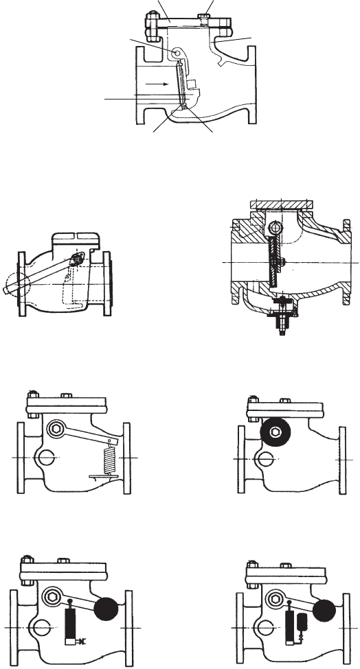
(a) Swin
g
check valve
Cover
Hinge pin
Door
Flow
Air plug
Bod
y
Seat ring Face ring
(
b
)
External lever and wei
g
ht
(
c
)
Inte
g
ral relief valve
(
d
)
External lever and axial s
p
rin
g(
e
)
External torsional s
p
rin
g
(
f
)
Air chamber + lever and wei
g
ht
(g)
C
y
linder and oil reservoir
Fig. 21.2. Swing check valve and modifications
Pressure transients in water engineering
so this part of the buoyant weight closure moment is modest. A large
opening angle means that the door has a relatively long way to travel
before reaching its seat, implying a greater time of closure. Seating
angle is often close to the vertical when installed in a horizontal pipeline
— the most common application — so that the lever arm r
m
sinðÞ
becomes very small as the door approaches its seat, rendering the
closure moment almost negligible at this stage. The valve may often
rely to some extent upon an actual reversed flow to push the door
onto its seat. On closure, subsequent abrupt elimination of the reversed
velocity can produce valve ‘slam’ with noise, vibration, high transient
pressure and possible damage.
These features of the swing check give this type of valve a relatively
poor closure performance, especially in larger sizes. Modifications can
be made to this valve in an effort to improve closure performance
and Fig. 21.2b—g illustrates a range of these.
Two fundamentally different approaches can be adopted when
deciding the way in which a check valve will behave during closure.
The free-acting behaviour of the basic valve can be enhanced to yield
a faster response. In these circumstances an ‘ideal’ free-acting valve
would close just at the moment of flow reversal. In practice there will
be some reflux V
o
, however small, when the door meets its seat.
Where this velocity produces an inertial head rise jaV
o
=gj, which is
413
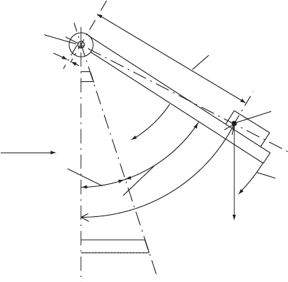
r
m
= distance to centre of gravity
+V
Seating angle = b
a = opening angle
W
s
= buoyant weight
dq/dt, d
2
q/dt
2
Centre of gravity
m = hinge friction
r
p
q
Fig. 21.3. Schematic of swing check valve door
Check valve characteristics
acceptable then the valve is considered satisfactory. On the other hand
if closure is protracted in relation to the rate of deceleration, a sub-
stantial reversed velocity V
o
can develop with a correspondingly large
inertial head rise when the valve shuts. Free-acting valve response
can be improved to give a smaller V
o
. Modelling of the pipeline
system can be carried out without detailed consideration of the specific
free-acting valve up until the moment of closure so that the methods
described in Chapter 20 can be employed without modification.
The second option to improve closure conditions is to delay the
valve closure and allow the reversed flow to develop. By controlling
the time of closure the reversed flow can gradually be ‘throttled’ up
until the moment of closure. Thus as the reversed flow is progres-
sively eliminated, the deceleration gradient dV=dt can be made as
low as necessary to avoid unacceptable transient effects on closure.
Response of this ‘damped’ valve has to be modelled as an integral
part of the pipeline network, including the characteristics of the
damping mechanism.
Using the common swing-check valve as an example both of the
above types of valve modification are considered. Alterations shown
in Fig. 21.2b—e retain the free-acting nature of the valve while Fig.
21.2f and 21.2g illustrate valve damping mechanisms.
21.2.1 Free-acting modifications
An external lever and weight can be added with the lever at an angle to
the valve door (Fig. 21.2b). This enhances the closure moment and
produces an important closing moment even when the door is close
to its seat. The angle between the valve door and the lever can be
used to alter closure performance or indeed to make it easier for the
valve to open if required, although this is liable to have a detrimental
affect on closure performance. The size of weight and the length of
lever arm also influences performance. The greater the additional
closing moment provided by the lever and weight the shorter the
closure time but with the penalty of increased flow velocity to get the
valve fully opened.
Two forms of external spring can be introduced. A linear spring
connected to the lever (Fig. 21.2d) or a torsional spring on the
projecting hinge shaft (Fig. 21.2e). When the valve is open the spring
is in tension and so additional closure moment is achieved without
significantly increasing the moment of inertia of moving parts. Spring
stiffness will improve performance, with a stiffer spring improving
414
Pressure transients in water engineering
closure performance but with the requirement for a higher velocity to
open the valve against the increased resistance.
A rule of thumb sometimes used is to consider use of measures to
improve closure performance when velocity through the valve exceeds
2.5 m/s.
A pressure relief valve which opens to alleviate transient pressure rise
on valve closure, can be included (Fig. 21.2c). A variation is to have a
bypass around the valve and to include a slow-closing valve within the
small bypass line. The bypass valve remains open until flow reverses,
acting as a pressure relief mechanism. The valve then closes slowly,
gradually decelerating flow in the bypass.
The free-acting swing check valve is best operated with the valve
fully open, as a partly open door may tend to ‘flutter’ causing accelerated
wear of the hinge.
To maintain pump prime a swing check valve or other pattern can be
included at the intake from a wet well. The valve is usually integral with
a strainer in these circumstances. Head loss through the strainer may
be 0:8V
2
=ð2gÞ.
21.2.2 Valve damping modifications
An air chamber can be attached to an external lever as shown in
Fig. 21.2f. As the valve opens, air can enter the chamber freely from
the atmosphere. When the valve starts to close, the air in the chamber
is compressed and pressure rises. A resistance force is produced which
increases as the valve door moves towards its seat. Controlled release
of air to atmosphere can be achieved using a flow-regulating valve.
Flow through the check valve is allowed to reverse and later as the
valve door nears its seat this reversed flow is gradually reduced to
zero, giving a quiet closure.
Figure 21.2g shows an oil-filled piston and oil reservoir. When the
valve is opening, a free flow of oil from the reservoir to the piston
cylinder takes place. As the valve closes, a flow-regulating valve
controls the rate at which oil returns to the reservoir. The piston move-
ment is also controlled and with it movement of the valve door. During
the controlled closure a reversed velocity is allowed to develop through
the check valve. As the valve door approaches its seat, this reversed
flow is throttled at a controlled rate with modest deceleration rates
dV=dt to give quiet valve closure.
A modification to the oil cylinder approach is to have the piston only
make contact with the lever during the final stages of closure so that the
415
Check valve characteristics
door moves freely towards its seat until the final stages of closure. The
piston can also be mounted internally to make contact with the door
itself.
A relatively slow-closing valve may allow high reversed velocity to
occur and the damping device may be unable to control the hydrody-
namic forces and can become unstable if not carefully chosen. A
quick-closing free-acting valve may be considered preferable in some
circumstances.
21.3 ‘Recoil’ valves
The closure performance of free-acting check valves having a rotating
door can be improved substantially if a number of changes are made
to the geometry of the valve. These improvements produced the
‘recoil’ check valve, an example of which is shown in Fig. 21.4a. This
valve remains suitable for both clean water and also sewage applica-
tions. The enhancements include:
(a) a weighted door which increases buoyant weight and closure
moment substantially
(b) a restricted ‘lift’ so that the valve door does not open to the same
degree as the simple swing check; this reduces travel distance
(c) a seating angle which is 30—408 from the vertical. This not only
reduces the travel distance of the valve door but also ensures
that a good lever arm and thus closure moment remains even as
a door nears its seat.
In larger sizes the good closure performance of a single-door valve,
which deteriorates as diameter increases, can be retained by having
several doors. Figure 21.4b shows a three-door pattern. Doors of
these larger valves can also be weighted as well as having a similar
seating angle as the smaller sizes. The lift of the valve door can likewise
be restricted. It should be noted that closure performance of these
valves has been optimised for a particular installation and the same
closure performance cannot be expected if the valve is placed in a
vertical riser. However, valves have been produced which are optimised
for vertically upwards flow and Fig. 21.4c depicts such a three-door
type.
These valves are suitable for application to water and sewage
systems with branch velocities typically 3—5 m/s. Recoil types should
be considered for high-lift, multi-pump applications.
416
Pressure transients in water engineering
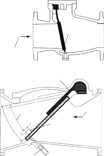
21.4 Tilting disk valve
Also known as a ‘slanting’ disk, this free-acting valve also relies on rota-
tion of the valve door to achieve closure but with the hinge partway
along the valve body (Fig. 21.5).
This valve has a good closure performance on account of its seating
angle and restricted opening angle. Some versions such as the Glenfield
type were specifically designed to have a low head drop.
The valve is available in wafer patterns such as the NAF check so
that reasonable space saving is achieved. The disk is light in weight
with low inertia and opens fully with a velocity of 0.6 m/s, thus avoiding
disk flutter. Seating angle is 158 from the vertical (in a horizontal line)
417
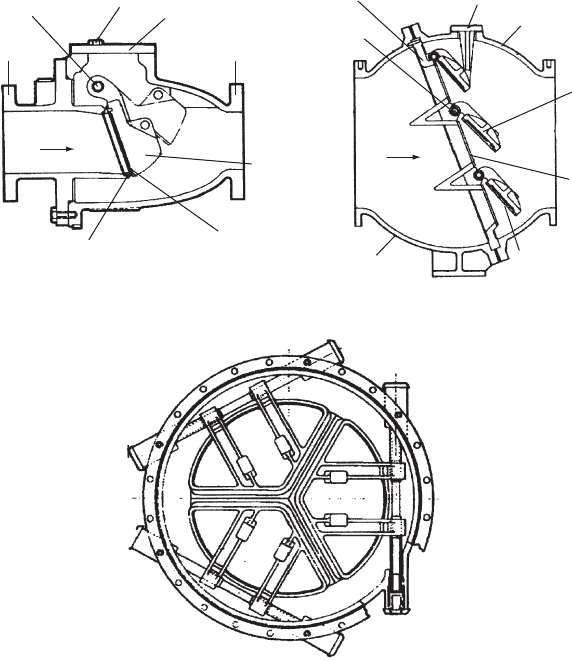
(b) Multi-door check valve(a) Glenfield recoil check valve
Flow
Inlet body
Flow
Outlet body
Doo
r
Seat
Face
Stopper
Diaphragm
Air plug
Cover
Hinge pin
Hinge pin
Outlet bodyInlet body
Door
Seat ring
Face ring
(
c
)
Multi-door check valve for verticall
y
u
p
wards flow
Fig. 21.4. ‘Recoil’ and multi-door check valves
Check valve characteristics
up to DN 450 and 108 for DN 500 or more. Auxiliary internal springs
can be fitted to enhance closure performance, with a reduction in
pressure rise of 75% after spring addition being measured in one test.
The valve is best suited to clean water applications rather than raw
sewage.
Tilting disk valves are not generally suitable for vertically downward
flow.
21.5 Rubber flap valve
Bearing a superficial resemblance to the swing check type is the
rubber flap valve (Fig. 21.6). This free-acting valve is simple in design
and is suitable for both clean water and sewage applications. The
valve has a door which is encased in rubber and the entire valve
418
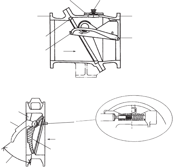
(a) Glenfield tiltin
g
disk valve
Body half
Face ring
Seat ring
Body hal
f
Disc
Air plugCover
Flow
Stop
Open
Shut
+
Opening angle
(b) Wafer-type body tiltin
g
disk
(c) Auxiliary torsional spring
Valve fitted with auxiliary
torsional springs
Fig. 21.5. Tilting disk valves
Pressure transients in water engineering
body is sometimes designed to accept a rubber lining. Instead of
having a hinge and shaft, a rubber strip is included. One end of the
strip is connected to the door and the other end is clamped in place
at the top of the valve body. Like the swing check, the door rotates
to open with the rubber strip bending. If the door is light the buoyant
weight closing moment will be more modest than with a heavier
door. The example shown in Fig. 21.6a will not have a good closure
performance and its merits lie in its simplicity. If the seat angle is
about 458 from the vertical, as illustrated in Fig. 21.6b, and angle of
travel is 358 then the buoyant weight moment remains significant
until closure, providing an improvement in closure performance. A
seat angled away from the vertical also helps to reduce overall valve
419
(
a
)
Flexible hin
g
e check valve
+
Normal flow direction
Closing disk
Ductile iron/nitrile coated
(b) Rubber flapper check valve
+
Normal flow direction
Flexible hinge
Free closure
Damped closure
Optional bottom buffer
Fig. 21.6. Rubber flapper check valves
Check valve characteristics
door travel and thus closure time. Since no shaft projects through the
valve body, the options of having external lever and weight or springs
to assist closure are not available with these valves.
In some valves, such as shown in Fig. 21.6b, the option of installing a
‘bottom buffer’ is available. This is in the form of a piston which projects
into the valve near to the bottom of the seat. When the closing door
makes contact with the piston over the final stages of closure,
the piston gradually moves back into an oil-filled cylinder, effectively
throttling any reversed flow which develops and controlling decelera-
tion rate dV=dt. This modification produces a damped closure over
the final stages of movement and it is necessary to know characteristics
of the oil cylinder and piston for any modelling exercise involving valve
closure.
Being rubber-coated, door closure will not be accompanied by the
sharp crack which is present with metal-to-metal seating.
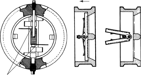
21.6 Split disk valve
Another pattern of free-acting valve which has become popular is the
split disk type (Fig. 21.7). It is composed of two lightweight semicircular
hinged doors. Valve closure is accomplished using a pair of torsional
springs. When installed in a horizontal line with the valve spindle
vertical, there is no buoyant weight moment to assist closure but
reliance is entirely on the springs. When installed in a vertically
upwards flow line, buoyant weight moment of the doors assists closure.
Conversely, in a vertically downwards flow, door weight retards closure.
Due to reliance on internal springs, the use of this type of valve is more
restricted, with installation in sewage schemes not advisable.
420
Shut Fully open
Normal flow direction
Torsional sprin
g
s
Fig. 21.7. Split disk valve with torsional springs
Pressure transients in water engineering
In terms of closure performance, the split disk valve is an improve-
ment on the basic swing check but does not match the recoil pattern.
Popularity of the valve rests on its lightweight, wafer design which
can be fitted between flanges, and its relatively lower cost. The space
saving achieved by using this valve can have an influence upon the
dimensions of pumping station buildings.
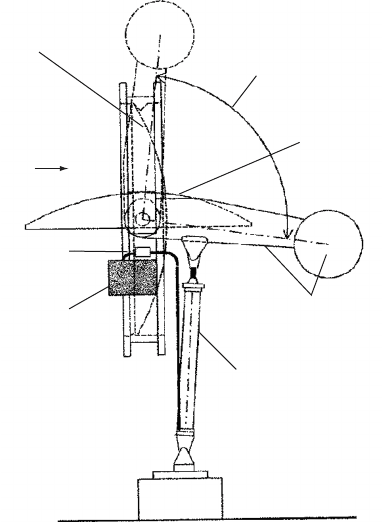
21.7 Butterfly valve used as a check valve
The butterfly valve can be fitted with an external lever and weight plus
an oil-filled cylinder to damp valve motion (Fig. 21.8). A locking device
is included which prevents the valve closing until pumping failure has
occurred. Typically a butterfly valve might be used on a larger diameter
of line, say DN 1400 or larger. Use of the damping mechanism, as for all
valves thus fitted, allows a substantial reversed flow to occur for an
appreciable time. Reversed rotation of pumps should be investigated.
In one instance the pump was running backwards at 150% of its
design forward speed and it is important to ensure that this is
421
Door closed
Door open
90∞
Flow direction
+
Oil flow regulating valve
Oil reservoir
Lever and weight
Cylinder connected to lever
Fig. 21.8. Butterfly valve as a check valve (simplified)
Check valve characteristics