Durst F. Fluid Mechanics: An Introduction to the Theory of Fluid Flows
Подождите немного. Документ загружается.

21.6 Turbulence Measurements with Hot-Wire Anemometers 685
21.6 Turbulence Measurements with Hot-Wire
Anemometers
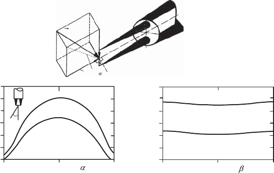
Velocity measurements by means of hot-wire anemometers require a detailed
knowledge of the directional sensitivity of the hot wire. The latter is deter-
mined by direct calibration of the hot wire in a flow with known direction.
Rotation of the wire leads to the velocity-angle representation of the outlet
signal of a hot-wire anemometer shown in Fig. 21.27. However, this informa-
tion is insufficient for using a hot-wire anemometer in turbulent flows, where
the angle of the local velocity changes continuously. For the evaluation of
the resulting output signal, it is necessary to know the velocity-angle depen-
dence of the hot-wire signal analytically. In this way, it is possible to record
the complex connections between turbulent velocity fluctuations and the an-
gle dependence on the HDA output signal quantitatively. Here, it is usual
to introduce an effective cooling velocity which for the velocity components
vertical and parallel to the hot wire can be expressed as follows:
ˆ
U
2
eff
=
ˆ
U
2
per
+ k
2
ˆ
U
2
par
, (21.32)
where
ˆ
U
per
is the momentary velocity component vertical to the hot wire
and U
par
the momentary parallel component; see, e.g. Hinze [21.1]. Equa-
tion (21.32) is characterized by the fact that the velocity components U
per
and U
par
are chosen as components, i.e. the components are expressed rela-
tive to the wire. For the flow measurements it is important, however, that the
velocity components are obtained for the measurements relative to a space-
fixed coordinate system x
i
. This makes it necessary to express
ˆ
U
per
and
ˆ
U
par
U
U
U
U
par
B
per
4.8
4.4
4.0
3.6
5.4
5.0
4.6
4.2
-90 0
90
-90 0
90
U
0
= 35 m/s
U
0
= 32 m/s
U
0
= 32 m/s
U
0
= 30 m/s
E Volt
[
]
E Volt
[]
α
U
par
= Velocity component
parallel to the wire
U
per
=
Velocity component
perpendicular to the wire
Fig. 21.27 Angle dependence of hot-wire signals

686 21 Introduction to Fluid-Flow Measurement
by the components
ˆ
U
i
. In this respect, for the velocity vector and the position
vector of the hot wire the following holds:
ˆ
U
i
=
<
ˆ
U
1
,
ˆ
U
2
,
ˆ
U
3
=
and !
i
= {cos α
1
, cos α
2
, cos α
3
} (21.33)
Hence,
ˆ
U
2
per
and
ˆ
U
2
par
can be given as follows:
U
2
per
=
ˆ
U
2
1
(cos
2
α
2
+cos
2
α
3
)+
ˆ
U
2
2
(cos
2
α
1
+cos
2
α
3
)+
ˆ
U
2
3
(cos
2
α
1
+cos
2
α
2
)
−2
ˆ
U
1
ˆ
U
2
cos α
1
cos α
2
− 2
ˆ
U
1
ˆ
U
3
cos α
1
cos α
3
− 2
ˆ
U
2
ˆ
U
3
cos α
2
cos α
3
(21.34)
and
U
2
par
=
ˆ
U
2
1
cos
2
α
1
+
ˆ
U
2
2
cos
2
α
2
+
ˆ
U
2
3
cos
2
α
3
+2
ˆ
U
1
ˆ
U
2
cos α
1
cos α
2
+2
ˆ
U
1
ˆ
U
3
cos α
1
cos α
2
+2
ˆ
U
2
ˆ
U
3
cos α
2
cos α
3
(21.35)
From these equations, the effective cooling velocity indicated in (21.32)
can be given as follows:
ˆ
U
2
eff
=
<
ˆ
U
2
1
!
k
2
cos
2
α
1
+cos
2
α
2
+cos
2
α
3
"
+
ˆ
U
2
2
!
cos
2
α
1
+k
2
cos
2
α
2
+cos
2
α
3
"
+
ˆ
U
2
3
!
cos
2
α
1
+cos
2
α
2
+k
2
cos
2
α
3
"
− 2
!
1−k
2
"
ˆ
U
1
ˆ
U
2
cos α
1
cos α
2
+
ˆ
U
1
ˆ
U
3
cos α
1
cos α
3
+
ˆ
U
2
ˆ
U
3
cos α
1
cos α
3
=
(21.36)
When expressing the momentary value of
ˆ
U
i
= U
i
+ u
i
, i.e. when introducing
the mean flow velocity U
i
and the turbulent fluctuation velocity u
i
, i.e.
ˆ
U
1
= U
1
+ u
1
,
ˆ
U
2
= U
2
+ u
2
,
ˆ
U
3
= U
3
+ u
3
(21.37)
(21.36) can be written as follows:
ˆ
U
2
eff
=
?7!
U
2
1
+2U
1
u
1
+ u
2
1
"!
k
2
cos
2
α
1
+cos
2
α
2
+cos
2
α
3
"
+
!
U
2
2
+2U
2
u
2
+ u
2
2
"!
cos
2
α
1
+ k
2
cos
2
α
2
+cos
2
α
3
"
+
!
U
2
3
+2U
3
u
3
+ u
2
3
"!
cos
2
α
1
+cos
2
α
2
+ k
2
cos
2
α
3
"8
− 2
!
1 − k
2
"
×[(U
1
U
2
+ U
1
u
2
+ U
2
u
1
+ u
1
u
2
)cosα
1
cos α
2
+(U
1
U
3
+ U
1
u
3
+ U
3
u
1
+ u
1
u
3
)cosα
1
cos α
3
+(U
2
U
3
+ U
2
u
3
+ U
3
u
2
+ u
2
u
3
)cosα
2
cos α
3
]} (21.38)
When one now considers the output signal of a hot-wire anemometer,
ˆ
E,
this is connected to the effective cooling velocity of the wire as follows:
ˆ
E =
A + B
ˆ
U
n
eff
1
2
(21.39)
21.6 Turbulence Measurements with Hot-Wire Anemometers 687
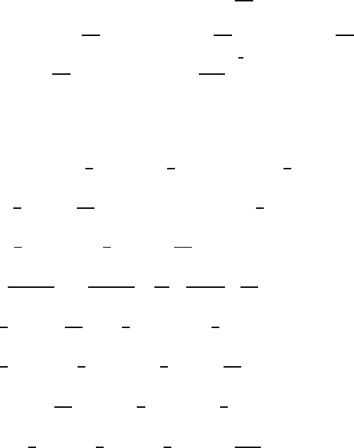
In order to explain the application of hot-wire anemometry for measurements
in turbulent flows, the following sequence of measurements needs to be con-
sidered, for which in Fig. 21.28 the selected hot-wire positions are shown. For
the equation to be given below, it is assumed that:
ˆ
U
1
= Q
1
+ q
1
,
ˆ
U
2
= q
2
,
ˆ
U
3
= q
3
(21.40)
hold. The position of the hot wire is described by the following directional
vector:
n
i
= {sin α, cos α, 0}
With this, the effective cooling velocity is computed as:
ˆ
U
2
eff
=
!
Q
2
1
+2Q
1
q
1
+ q
2
1
"!
k
2
sin
2
α +cos
2
α
"
+ q
2
2
+
!
sin
2
α + k
2
cos
2
α
"
+ q
2
3
+2
!
1 − k
2
"
q
1
q
2
sin α cos α
+2
!
1 − k
2
"
Q
1
q
2
sin α cos α (21.41)
Rearrangement of the above equation yields:
ˆ
U
eff
= Q
1
cos α
1+
!
k
2
tan
2
α
"
+2
!
1+k
2
tan
2
α
"
q
1
Q
1
+2
7!
1 − k
2
"
tan α
8
q
2
Q
1
+
!
1+k
2
tan
2
α
"
q
2
1
Q
2
1
+
!
k
2
+tan
2
α
"
q
2
2
Q
2
1
+
!
1+tan
2
α
"
q
2
3
Q
2
1
+2
7!
1 − k
2
"
tan α
8
q
1
q
2
Q
2
1
1
2
(21.42)
By series expansion and after neglecting terms of higher order the following
relationships result:
ˆ
U
eff
(α)=Q
1
cos α
1+k
2
1
2
tan
2
α − k
4
1
8
tan
4
α +
1+k
2
1
2
tan
2
α
− k
4
1
8
tan
4
α
q
1
Q
1
+
tan α − k
2
tan α
1+
1
2
tan
2
α
+ k
4
1
2
tan
3
α
1+
3
4
tan
2
α
q
2
Q
1
+
1
2cos
2
α
− k
2
tan
2
α
4cos
2
α
+
3
16
k
4
tan
4
α
cos
2
α
q
2
3
Q
2
1
−
3
8
k
4
tan
4
α
q
2
1
Q
2
1
k
2
1
2
+tan
2
α1+
1
2
tan
2
α
−
3
2
k
4
tan
2
α
1
2
+tan
2
α +
5
8
tan
4
α
q
2
2
Q
2
1
− k
4
tan
4
α
q
3
1
Q
3
1
+
−k
2
1
2
+tan
2
α +
1
2
tan
4
α
+ k
4
3
4
tan
2
α +
3
4
tan
4
α +
9
2
tan
6
α
q
1
q
2
2
Q
3
1
688 21 Introduction to Fluid-Flow Measurement
+ k
4
6tan
3
α −
9
4
tan
5
α
q
2
q
2
1
Q
3
1
+
k
2
tan
2
α
4cos
2
α
+ k
4
tan
4
α
3
4
tan
2
α +
3
cos
2
α
q
1
q
2
3
Q
3
1
+
k
2
tan
2
α
2cos
2
α
1+
3
2
tan
2
α
+ k
4
3
4
tan
3
α −
3tan
3
α
2cos
2
α
+3
tan
5
α
cos
2
α
q
2
q
2
3
Q
3
1
+
−k
2
tan α
1
2
+tan
2
α +
1
2
tan
4
α
+ k
4
1
2
tan α +
15
4
tan
3
α +
15
4
tan
5
α −
1
16
tan
7
α
q
3
2
Q
3
1
(21.43)
When one introduces (21.43) in (21.39), one obtains for the time-averaged
voltage of a hot-wire anemometer
E
2
− A
∼
=
BQ
n
1
cos
n
α
1+
n
2
k
2
tan
2
α
(21.44)
For the momentary value, considering only terms of first order, the following
results:
E
2
+2Ee − A
∼
=
BQ
n
1
cos
n
α
1+
n
2
k
2
tan
2
α + n
!
1+k
2
tan
2
α
"
×
q
1
Q
1
+ n
!
1 − k
2
"
tan α
q
2
Q
2
(21.45)
By subtraction of (21.44) from (21.45) and squaring the difference, one
obtains
[2E]
2
e
2
∼
=
n
2
B
2
Q
2n
1
cos
2n
α
!
1+k
2
tan
2
α
"
q
1
Q
1
+
!
1 − k
2
"
tan α
q
2
Q
1
2
(21.46)
and, hence, the following final equations can be employed for evaluation of
hot-wire anemometer signals:
!
E
2
− A
"
2
= B
2
Q
2n
1
cos
2n
α
!
1+k
2
tan
2
α
"
(21.47)
or rewritten
2E
E
2
− A
2
e
2
∼
=
n
2
3
q
1
Q
1
+
!
1 − k
2
"
tan α
!
1+k
2
tan
2
α
"
q
2
Q
1
4
2
(21.48)
By time-averaging, one obtains
2E
E
2
− A
2
e
2
= n
2
⎧
⎨
⎩
q
1
Q
1
2
+
3
!
1 − k
2
"
tan α
!
1+k
2
tan
2
α
"
4
2
q
2
Q
1
2
+
2
!
1 − k
2
"
tan α
!
1+k
2
tan
2
α
"
q
1
q
2
Q
2
1
5
(21.49)
21.6 Turbulence Measurements with Hot-Wire Anemometers 689
Three measurements with the angular positions α
1
=0,α
2
= π/4andα
3
=
−π/4 yield
q
2
1
Q
2
1
=
1
n
2
3
2E
α
1
!
E
2
α
1
− A
"
4
2
e
2
α
1
(21.50)
q
2
2
Q
2
1
=
1
2n
2
3
!
1+k
2
"
(1 − k
2
)
4
2
3
2E
α
2
E
2
α
2
− A
2
e
2
α
2
+
2E
α
3
E
2
α
3
− A
2
e
2
α
3
−
2E
α
1
E
2
α
1
− A
2
e
2
α
1
4
(21.51)
q
2
q
2
Q
2
1
=
1
n
2
!
1+k
2
"
4(1− k
2
)
3
2E
α
2
E
2
α
2
− A
2
e
2
α
2
−
2E
α
3
E
2
α
3
− A
2
e
2
α
3
4
(21.52)
In order to obtain also the components in the x
1
–x
3
plane, i.e. in order to
measure
q
2
3
and q
1
q
3
, one chooses the wire positions in Fig. 21.28. For these
positions, additional information results which can be used for measuring the
subsequent quantity.
q
2
3
Q
2
1
=
1
2n
2
3
!
1+k
2
"
(1 − k
2
)
4
2
3
2E
α
4
E
2
α
4
− A
2
e
2
α
4
+
2E
α
5
E
2
α
5
− A
2
e
2
α
5
−
2E
α
1
E
2
α
1
− A
2
e
2
α
1
4
(21.53)
Fig. 21.28 Wire positions for sequence of hot-wire measurements
690 21 Introduction to Fluid-Flow Measurement
U
w
u
Fig. 21.29 Straight probe in flow field
q
1
q
3
Q
2
1
=
1
n
2
3
!
1+k
2
"
4(1− k
2
)
43
2E
α
4
E
2
α
4
− A
2
e
2
α
4
−
2E
α
5
E
2
α
5
− A
2
e
2
α
5
4
(21.54)
The above evaluation equations can thus be used to measure the mean flow
component Q
1
= U
1
and the turbulence quantities q
2
1
= u
2
1
, q
2
2
= u
2
2
, q
2
3
= u
2
3
,
q
2
q
1
= u
2
u
1
and q
1
q
3
= u
1
u
3
. Measurements of other correlations can be
carried out on the basis of correspondingly derived equations.
A usually employed quantity for describing the turbulence intensity is the
degree of turbulence, Tu. The mean fluctuation velocity
u
2
containedinit
is determined from the RMS value of the anemometer output voltage (RMS
value)
e
2
of a straight hot-wire probe (Fig. 21.29), divided by the gradient
of the static calibration curve of the same probe, i.e.
Tu=
u
2
U
100 (%) =
e
2
dE
dU
U
100 (%) (21.55)
When basing the computation on the modified King’s law:
E
2
= A + BU
n
(21.56)
differentiation yields
d
¯
E
d
¯
U
=
nB
¯
U
n−1
2
√
A + B
¯
U
n
(21.57)
On inserting in this differential equation once again the above King’s equation
one obtains, together with the theoretical exponents n, the working equation
for determining the turbulence degree
Tu=
u
2
¯
U
=
4 ×
¯
E
e
2
× 100
¯
E
2
− A
(%) (21.58)
This equation indicates that for small fluctuations of the flow velocity, with
a mean velocity value
¯
U, the effective value of the velocity fluctuations is
proportional to the RMS value of the voltage fluctuation of the anemometer.
21.6 Turbulence Measurements with Hot-Wire Anemometers 691
U
U cos
U sin
.
d
U = U + u
Fig. 21.30 Notations of the velocity component
As already emphasized, for the determination of the Reynolds momen-
tum transport terms
u
i
u
j
, one has to employ inclined probes (probe inclined
towards
¯
U by an angle α mostly α = ±45
◦
). In this case, the anemome-
ter output voltage is made up of velocity components of contributions of
the longitudinal and lateral velocity components of a space-fixed coordinate
system (Fig. 21.30). Thus it was shown in previous sections above that the
determination of the Reynolds momentum-transport terms becomes possible.
Simplified considerations, yet well suited for an introduction, are possible
on the assumption that the hot wire is sensitive only to the vertical velocity
component U cos α. The velocity components parallel to the hot wire and
vertical on the plane formed of the hot wire and its prongs are neglected, so
that the modified King’s law reads:
ˆ
E
2
= A + B
ˆ
U cos ˆα
n
(21.59)
Differentiation of this equation yields
2
ˆ
E d
ˆ
E = B cos
n
αn
ˆ
U
n−1
d
ˆ
U − Bnsin ˆα cos
n−1
α
ˆα
ˆ
U
n
dα (21.60)
When the velocity fluctuations of a turbulent flow are small in comparison
with the mean flow velocity U, one can set
d
ˆ
U = u,
ˆ
U dα = v
With this simplifying assumptions, the following results:
2
ˆ
E d
ˆ
E = nB
ˆ
U cos ˆα
n
1
ˆ
U
(u − v tan ˆα) (21.61)
From the modified King’s law, one obtains
B (U cos ˆα)
n
=
ˆ
E
2
− A, (21.62)
where
ˆ
E is once again the anemometer output voltage at the flow velocity
ˆ
U.
From the latter two equations, it can be derived that
692 21 Introduction to Fluid-Flow Measurement
2
ˆ
E
ˆ
E
2
− A
d
ˆ
E =
n
¯
U
(u − v tan ˆα) (21.63)
with
2
ˆ
E
ˆ
E
2
− A
≈
2
¯
E
¯
E
2
− A
= D and d
ˆ
E = e (21.64)
Combining the equations, one obtains
eD =
n
¯
U
(u − v tan α) (21.65)
Squared and time-averaged, one obtains the basic equation for the RMS value
of the anemometer output voltage, when positioning the probe in the u, v
plane:
D
2
e
2
=
n
2
¯
U
2
u
2
+ v
2
tan
2
α − 2uv tan
2
α
, (21.66)
where
e
2
=RMS value of the anemometer output voltage.
For a measurement with the +α inclined and the −α inclined probe in the
u–v plane (Fig. 21.31), one obtains the following:
+α inclined probe:
D
2
e
2
1
=
n
2
¯
U
2
u
2
+ v
2
tan
2
α − 2uv tan
2
α
(21.67)
−α inclined probe:
D
2
e
2
2
=
n
2
¯
U
2
u
2
+ v
2
tan
2
α − 2uv tan
2
α
(21.68)
The difference of (21.67) and (21.68) produces the turbulent shear stresses
(up to density ρ):
uv
¯
U
2
tan
2
α
=
1
4n
2
D
2
e
2
1
− e
2
2
(21.69)
The sum yields
u
2
¯
U
2
+
v
2
¯
U
2
tan
2
α =
1
2n
2
D
2
e
2
1
+ e
2
2
(21.70)
With known probe angle α (mostly α =45
◦
) and previously measured u
2
/
¯
U
2
from the above equation, v
2
/
¯
U
2
can be computed.
U
U
w
w
u
u
=
4
=
4
Fig. 21.31 Measurements with inclined probe in u, v plane
21.6 Turbulence Measurements with Hot-Wire Anemometers 693
=
4
=
4
w
u
w
u
U
U
U
u
w
Position 0
Position 2
Position1
Fig. 21.32 The measured signals of a linearized anemometer and a sensor sensitive
only against the vertical velocity components
For the normal probe, α =0
◦
, the following results from the basic equation,
an already known value:
D
2
e
2
0
=
n
2
¯
U
2
u
2
(21.71)
The still remaining turbulence intensity
w
2
/
¯
U
2
is similar to what is described
above, with the only difference that the probe has to be positioned in the
u, w plane, so that in the above equations v only has to be replaced by w.
In the case of a linearized anemometer, with a voltage output proportional
to U, i.e.
E = SU (21.72)
the evaluation of hot-wire signals is simplified considerably. Assuming further,
on the other hand, that the hot wire is only sensitive to the vertical velocity
components (Fig. 21.32), one arrives at the following connections:
Position 0 : α =0 e
0
= a
0
u;
¯
E = a
0
¯
U (21.73)
Position 1 : α
1
=45
◦
e
1
= au + bv (21.74)
Position 2 : α
2
= −45
◦
e
2
= au − bv (21.75)
From these three equations, one obtains by squaring and time averaging:
e
2
0
= a
2
0
u
2
(21.76)
e
2
1
= a
2
u
2
+ b
2
v
2
+2abuv (21.77)
e
2
2
= a
2
u
2
+ b
2
v
2
− 2abuv (21.78)
From the RMS values, the flow parameters can be determined:
u
2
=
1
a
2
0
e
2
0
(21.79)
v
2
=
e
2
1
+ e
2
2
2b
2
−
a
2
b
2
u
2
(21.80)
uv =
e
2
1
− e
2
2
4ab
(21.81)
When an X-probe is used in the measurements, e
1
and e
2
are measured
simultaneously with two separate electric systems (Fig. 21.33). For the flow
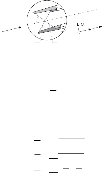
694 21 Introduction to Fluid-Flow Measurement
a
u
Velocity fluctuations
u
Flow direction
Hot-wire
II
Hot-wire I
Probe-axis
Fig. 21.33 Measurement signals of an X-probe
parameters, the following evaluation would also be possible:
u =
1
2a
(e
1
+ e
2
) (21.82)
v =
1
2a
(e
1
− e
2
) (21.83)
The output signals are then processed such that the sought flow parameters
can be determined, i.e. the following quantities:
u
2
=
1
4a
2
(e
1
+ e
2
)
2
(21.84)
v
2
=
1
4b
2
(e
1
− e
2
)
2
(21.85)
uv =
1
4ab
e
2
1
− e
2
2
(21.86)
Quantities that depend on squares of differences of small voltages can only
be determined very inaccurately.
21.7 Laser Doppler Anemometry
21.7.1 Theory of Laser Doppler Anemometry
The physical background of optical velocity measurements by means of laser
light beams, discussed in this section, is the Doppler effect, which leads to
measurable frequency changes of the laser light, that are generated by the
movements of light scattering particles. The prerequisite for the applicability
of optical velocity measurement procedures, therefore, is the existence of ap-
propriate light-scattering particles, which either exist naturally in the flowing
fluid, or need to be added by particle generators. These particles serve as re-
ceiver and transmitter of the incident laser light and bring about, by their
motion, the desired frequency changes of the laser radiation. These frequency
changes are measured and from the measurements one induces the velocities