Durst F. Fluid Mechanics: An Introduction to the Theory of Fluid Flows
Подождите немного. Документ загружается.


258 9 Stream Tube Theory
The flange force F on the control volume in Fig. 9.5 is computed from the
integral momentum equation as follows:
−ρU
2
D
π
4
D
2
+ ρU
2
d
π
4
d
2
−P
D
π
4
D
2
+ P
O
π
4
D
2
−
π
4
D
2
(P
D
−P
O
)
= F (9.39)
or, after rearrangement, in consideration of (9.38):
−
ρ
2
π
4
D
2
U
2
D
2 − 2
d
2
D
2
U
2
d
U
2
D
−
π
4
D
2
ρ
2
D
2
d
4
− 1
U
2
D
= F (9.40a)
and after further rearrangement:
−
ρ
2
π
4
D
2
U
2
D
1 −
D
2
d
2
2
= F (9.40b)
On inserting the corresponding relationships for U
D
from (9.35), one obtains
for the flange force F
A = −
˙m
2
ρ
π
2
D
2
1 −
D
2
d
2
2
(9.41)
The force applied by the flange on the examined nozzle part proves to be
positive, so that the supporting surface of the flange receives a negative force
F . The screws in the flange can therefore be regarded to be force free as far
as any contribution from the flow is concerned. The nozzle is pressed on to
the flange.
9.3.2 Sudden Cross-Sectional Area Extension
In practical fluid mechanics, often pipes of different cross-sections are lined
up and flows proceed through them. In this way, viewed in the flow direction,
internal flows result that are exposed to sudden cross-section widenings, as
shown in Fig. 9.6. In this manner separation areas are generated whose influ-
ence on the flow can be understood from the following considerations. When
treating flows with sudden changes in their cross-sectional area, mass conser-
vation between the planes A and B of the pipe flow exists, and thus yields
from the continuity equation:
˙m
ρ
= U
d
π
4
d
2
= U
D
π
4
D
2
(9.42)
Hence the velocities U
d
and U
D
can be determined by the given mass flow
˙m, if the density of the fluid is known, and also the cross sectional areas.
In the case of flows passing through the considered region without losses,
the following difference in pressure would result between the planes A and B,
which can be computed from the Bernoulli equation:
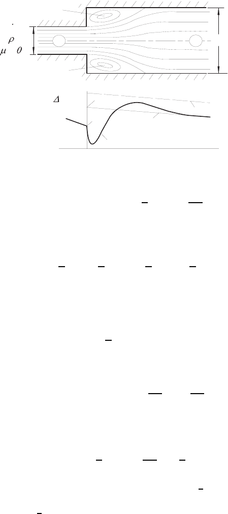
9.3 Incompressible Flows 259
.
P
verl
{
P
P
P
P
ideal
real
A
B
Pressure distribution
m
d
A
B
D
Separation
region
Separation
region
=
Fig. 9.6 Carnot’s impact diffusor
∆P
ideal
=(P
B
− P
A
)
ideal
=
ρ
2
U
2
d
1 −
d
4
D
4
(9.43)
Under real conditions, as indicated in Fig. 9.6 by the occurrence of the sep-
aration areas, the following momentum equation results:
F = ρU
2
d
π
4
− ρU
2
D
π
4
D
2
+ P
A
π
4
d
2
− P
B
π
4
D
2
(9.44)
When one neglects the contributions to the force F by momentum losses at
the pipe walls, then the force F can be computed as the pressure force on
the ring surface after the sudden expansion of the pipe, i.e. as
F = P
A
π
4
!
D
2
− d
2
"
(9.45)
Thus one obtains for the pressure difference
∆P
real
=(P
A
− P
B
)
real
= ρU
2
d
d
2
D
2
1 −
d
2
D
2
, (9.46)
so that a pressure loss (Carnot’s momentum loss) can be determined as
follows:
∆P
loss
=∆P
ideal
− ∆P
real
=
ρ
2
U
2
d
1 −
d
4
D
4
=
ρ
2
!
U
2
d
− U
2
D
"
(9.47)
For D →∞resultsasamaximumvaluefor∆P
loss
=
ρ
2
U
2
d
, the discharge
pressure loss. This means that there is no diffusor available to convert the
“dynamic pressure”
1
2
ρU
2
d
back into “static pressure”.
260 9 Stream Tube Theory
9.4 Compressible Flows
9.4.1 Influences of Area Changes on Flows
The general treatment here provides information on what effect cross-sectional
changes in flow channels have on fluid flows, i.e. to what extent and in which
way area changes determine the distribution of velocity, pressure, density and
temperature along the channel. The equations that were derived in Sect. 9.2
are employed, i.e. the continuity equation reads:
˜ρ
˜
U
1
A = constant (9.48)
Equation (9.48) can be written in differential form as:
dA
A
+
d˜ρ
˜ρ
+
d
˜
U
1
˜
U
1
= 0 (9.49)
According to the considerations in Sect. 9.2, the variation of the velocity
in the flow direction can be described, as a first approximation, by Euler’s
equation, reduced for one-dimensional flows, i.e.
˜ρ
˜
U
1
d
˜
U
1
dx
1
= −
d
˜
P
dx
1
= −
d
˜
P
d˜ρ
d˜ρ
dx
1
(9.50)
On the basis of the energy equation, written for reversible adiabatic fluid
flows, the following relationship holds:
˜
P
˜ρ
κ
= constant (9.51)
Under these adiabatic conditions, the differentiation of
˜
P with respect to ρ
yields the sound velocity c:
˜c
2
=
*
d
˜
P
d˜ρ
+
ad
(9.52)
Equation (9.52) introduced into (9.50) yields the following relationship:
˜ρ
˜
U
1
d
˜
U
1
dx
1
= − ˜c
2
d˜ρ
dx
1
(9.53)
When one introduces the Mach number Ma of the flow as:
>
Ma =
˜
U
1
˜c
(9.54)
9.4 Compressible Flows 261
(9.53) can be written as:
d˜ρ
˜ρ
= −
>
Ma
2
d
˜
U
1
˜
U
1
(9.55)
Inserting the density variation in (9.55) in (9.49), one obtains:
dA
A
−
>
Ma
2
d
˜
U
1
˜
U
1
+
d
˜
U
1
˜
U
1
= 0 (9.56)
or
d
˜
U
1
˜
U
1
=
−1
(1 −
>
Ma
2
)
dA
A
(9.57)
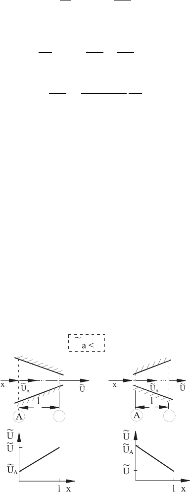
When one takes into consideration that subsonic flows are given by
>
Ma < 1
and supersonic flows by
>
Ma > 1, the above relationship expresses:
• In the presence of a subsonic flow (
>
Ma < 1), a decrease in the cross-
sectional area of a flow channel in the flow direction is linked to an increase
in the flow velocity. An increase in the channel cross-sectional area in the
flow direction results in a decrease in the flow velocity (see Fig. 9.7).
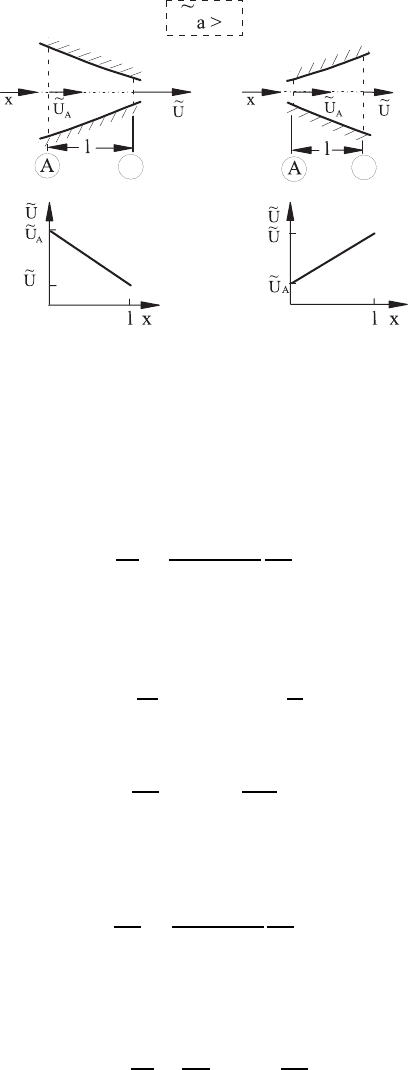
• In the presence of a supersonic flow (
>
Ma > 1), a decrease in the cross-
sectional area of a flow channel in the flow direction is linked to a decrease
in the flow velocity. An increase in the flow cross-section in the flow
direction results in an increase in the flow velocity (see Fig. 9.8).
In addition to the changes in the flow velocity, caused by changes in the
cross-sectional areas, the changes in pressure, density and temperature of the
flowing fluid are also of interest. From (9.51), it can be seen that the relative
change in density always has the opposite sign to the change in velocity,
i.e. the density increases in the flow direction when the velocity decreases
and vice versa. In the region of subsonic flow, the locally present relative
B
M1
11
B
B
B
B
B
1
1
Fig. 9.7 Influence of a change in the flow cross-section on a subsonic flow
262 9 Stream Tube Theory
11
B
B
B
B
B
B
11
M
1
Fig. 9.8 Influence of a change in the flow cross-section on a supersonic flow
change in density is smaller than the local relative change in velocity. In the
region of supersonic flow, the locally present relative change in density is
larger than the relative change in velocity. The changes in the density for the
corresponding changes in cross-sectional area changes of the flow channel are
given by the relationship:
d˜ρ
˜ρ
=
>
Ma
2
(1 −
>
Ma
2
)
dA
A
(9.58)
With regard to the pressure variation, the following considerations can be
carried out. From the adiabatic pressure-density relationship (9.51), the
following results:
d
˜
P =
˜
P
˜ρ
κ
κ˜ρ
(κ−1)
d˜ρ = κ
˜
P
˜ρ
d˜ρ (9.59)
Therefore, for the local relative change in pressure one can derive:
d
˜
P
˜
P
= κ
>
Ma
2
d
˜
U
1
˜
U
1
(9.60)
or with regard to the local relative change in the cross-sectional area of the
flow, the following relative change in pressure results:
d
˜
P
˜
P
=
κ
>
Ma
2
(1 −
>
Ma
2
)
dA
A
(9.61)
Finally, it is necessary to consider the variations in temperature. For this
purpose, the state equation for ideal gases is differentiated:
−
˜
P
d˜ρ
˜ρ
2
+
d
˜
P
˜ρ
= Rd
˜
T
dA
A
(9.62)
9.4 Compressible Flows 263
or rewritten in the following form:
−
d˜ρ
˜ρ
+
d
˜
P
˜
P
=
d
˜
T
˜
T
(9.63)
Hence, knowing
d˜ρ
˜ρ
and
d
˜
P
˜
P
, the following relationship for the temperature
changes results:
d
˜
T
˜
T
= −(κ − 1)
>
Ma
2
d
˜
U
1
˜
U
1
(9.64)
The locally occurring relative change in temperature has the opposite sign
to the local relative change in velocity. The relative changes in temperature
are weaker than the corresponding relative changes in density. With regard
to the relative area change of the flow cross-section, it results that
d
˜
T
˜
T
=
(κ − 1)
>
Ma
2
(1 −
>
Ma
2
)
dA
A
(9.65)
The considerations stated for the flow velocity variations in supersonic and
subsonic flows, which are sketched in Figs. 9.7 and 9.8, can also be carried
out for the variations in pressure, density and temperature with the aid of
the above equations.
Another important result of the above derivations can be stated through
a rearrangement of the relationships derived above, such that the following
equation holds:
dA
d
˜
U
1
=
A
˜
U
1
(1 −
>
Ma
2
) (9.66)
This relationship expresses that the condition for achieving the sound velocity
is given by dA = 0, i.e.
>
Ma = 1. Since for the second derivative of A
d
2
A
d
˜
U
2
1
=
A
˜
U
2
1
>
Ma
2
(
>
Ma
2
− 2) (9.67)
for
>
Ma = 1 the condition for some flow to exist is given by a minimum of the
flow cross-section. Further considerations of changes if errors sectional area
are given in refs. [9.1] to [9.5].
9.4.2 Pressure-Driven Flows Through Converging
Nozzles
In many technical plants, flows of gases occur which are to be classified into a
group of flows that take place between reservoirs with differing pressure lev-
els. Gases, for example, are often stored under high pressure in large storage
reservoirs, in order to be discharged through conduits for the intended pur-
pose when need arises. This discharge can be idealized as a “equalization flow”
264 9 Stream Tube Theory
between two reservoirs or two chambers of which one represents the storage
reservoir under pressure, while the environment represents the second reser-
voir. In the following considerations it is assumed that both reservoirs are very
large, so that constant reservoir conditions exist during the entire “equaliza-
tion flow” under investigation. These are assumed to be known and are given
by the pressure P
H
, the temperature T
H
, etc., in the high-pressure reservoir,
and also through the pressure P
N
and temperature T
N
for the low-pressure
reservoir. The compensating flow takes place via a continually converging
nozzle as indicated in Fig. 9.9, whose largest cross-section thus represents the
discharge opening of the high pressure reservoir, whereas the smallest nozzle
cross-section represents the inlet opening into the low-pressure reservoir.
When one wants to investigate the fluid flows taking place in the above
equalization flow in more detail, the final equations for flows through chan-
nels, pipes, etc., derived in Sect. 9.2 can be used:
˜ρ
˜
U
1
A = constant (9.68)
˜
h +
1
2
˜
U
2
1
= constant;
˜
P
˜ρ
κ
= constant (9.69)
˜
P
˜ρ
= R
˜
T (9.70)
With (9.68)–(9.70), a sufficient number of equations exists to determine the
changes in the area-averaged velocity and the area-averaged thermodynamic
state quantities of the flowing gas. Hence the velocity, pressure, temperature
and density along the x
1
axis, shown in Fig. 9.9, can be found by solving this
set of equations.
When one considers that, based on the assumption of a large high-pressure
reservoir there is the constant pressure P
H
and the velocity (U
1
)
H
=0,then
for the velocity U
1
at each point x
1
of the nozzle the following relationship
can be stated to be valid:
Container 1
Container
2
P
T
P
T
H
H
H
N
N
N
x =0
1
x =L
1
F(x )
1
1
x
Fig. 9.9 Flow between two reservoirs through a converging nozzle
9.4 Compressible Flows 265
˜
h +
1
2
˜
U
2
1
= h
H
(9.71)
Taking into account that the enthalpy for an ideal gas can be stated as c
P
T
and moreover that the ideal gas equation (9.70) holds, (9.71) can be rewritten
as follows:
c
P
˜
P
R˜ρ
+
1
2
˜
U
2
1
=
κ
κ − 1
˜
P
˜ρ
+
1
2
˜
U
2
1
=
κ
κ − 1
P
H
ρ
H
(9.72)
The velocity U
1
is thus linked to the change in the pressure along the axis of
the nozzle as follows:
˜
U
1
=
9
:
:
;
2κ
κ − 1
*
P
H
ρ
H
−
˜
P
˜ρ
+
(9.73)
The above equation indicates that for
˜
P = 0, i.e. for the outflow into a
vacuum, a maximum possible flow velocity develops which is given by the
state of the reservoir only:
U
max
=
$
2κ
κ − 1
P
H
ρ
H
=
2c
P
T
H
(9.74)
Standardizing the flow velocity U
1
, existing at a point x
1
,withU
max
,one
obtains:
˜
U
1
U
max
=
$
1 −
˜
P · ρ
H
P
H
˜ρ
(9.75)
or rewritten by taking the ideal gas equation into account:
˜
U
1
U
max
=
$
1 −
˜
T
T
H
(9.76)
Linking the adiabatic equation (9.86) to the state (9.70) leads to the following
relationships:
˜
T
T
H
=
˜ρ
ρ
H
κ−1
and
˜
T
T
H
=
*
˜
P
P
H
+
κ−1
κ
(9.77)
Thus the following equations hold:
˜
U
1
U
max
=
9
:
:
;
3
1 −
˜ρ
ρ
H
κ−1
4
(9.78)
266 9 Stream Tube Theory
and
˜
U
1
U
max
=
9
:
:
:
;
⎡
⎣
1 −
*
˜
P
P
H
+
κ−1
κ
⎤
⎦
(9.79)
On choosing the normalized velocity (
˜
U
1
/U
max
) as a parameter for the repre-
sentation of the flow in the nozzle, the distributions of pressure, density and
temperature along the nozzle can be stated as follows:
˜
P
P
H
=
⎡
⎣
1 −
*
˜
U
1
U
max
+
2
⎤
⎦
κ
κ−1
(9.80)
˜ρ
ρ
H
=
⎡
⎣
1 −
*
˜
U
1
U
max
+
2
⎤
⎦
1
κ−1
(9.81)
˜
T
T
H
=
⎡
⎣
1 −
*
˜
U
1
U
max
+
2
⎤
⎦
(9.82)
These relationships are shown in Fig. 9.10 as functions of (
˜
U
1
/U
max
). Also,
along the (
˜
U
1
/U
max
) axis, the corresponding Mach number of the flow is
plotted, which under consideration of the relationship c =
(dP/ dρ)
ad
=
√
κRT can be shown to be identical with
˜
U
2
1
U
2
max
=
˜
U
2
1
2c
P
T
H
κR
˜
T
κR
˜
T
=
>
Ma
2
1
κ − 1
2
*
˜
T
T
H
+
(9.83)
Fig. 9.10 Distributions of the pressure, density and temperature as a function of
the local normalized velocity or as a function of the local Mach number

9.4 Compressible Flows 267
When one considers the relationship derived above for (T/T
H
), in (9.77), one
obtains for the Mach number the following dependence on (
˜
U
1
/U
max
):
>
Ma =
9
:
:
:
:
:
:
:
:
:
;
2
κ − 1
⎧
⎪
⎪
⎪
⎪
⎪
⎪
⎨
⎪
⎪
⎪
⎪
⎪
⎪
⎩
*
˜
U
1
U
max
+
2
⎡
⎣
1 −
*
˜
U
1
U
max
+
2
⎤
⎦
⎫
⎪
⎪
⎪
⎪
⎪
⎪
⎬
⎪
⎪
⎪
⎪
⎪
⎪
⎭
(9.84)
Hence a Mach number of the flow can be assigned to each value of an area-
averaged velocity normalized with the maximum velocity.
All quantities which are stated in (9.80)–(9.82) can also be written as
functions of the Mach number
>
Ma. This in turn can be considered as an
area-averaged flow quantity describing the distributions of the flow along the
x
1
axis.
For the derivation showing the dependence of the pressure, density and
temperature on the Mach number of the flow, shown graphically in Fig. 9.10,
(9.71) is written as follows:
c
P
˜
T +
1
2
˜
U
2
1
= c
P
T
H
(9.85)
By division with c
P
˜
T one obtains
T
H
˜
T
=1+
˜
U
2
1
2c
P
˜
T
κR
κR
=1+
κ − 1
2
>
Ma
2
1
(9.86)
or for the reciprocal
˜
T
T
H
=
2
2+(κ − 1)
Ma
2
1
(9.87)
This equation makes it clear that there is a relationship between the area-
averaged temperature at a location on the x
1
axis and the Mach number
existing at the same point of the flow. Hence it becomes clear that for each
point x
1
the temperature can be computed when the high-pressure reservoir
temperature is given and the Mach number of the flow is known.
Taking into account the adiabatic equation, the relationship between the
pressure
˜
P and reservoir pressure P
H
is given by
˜
P
P
H
=
*
˜
T
T
H
+
κ
κ−1
=
3
2
2+(κ − 1)
Ma
2
1
4
κ
κ−1
(9.88)
and the corresponding relationship for the density is
˜ρ
ρ
H
=
*
˜
T
T
H
+
1
κ−1
=
3
2
2+(κ − 1)
Ma
2
1
4
1
κ−1
(9.89)