Du C., Xie L. Modeling and Control of Vibration in Mechanical Systems
Подождите немного. Документ загружается.

284 Modeling and Control of Vibratio n in Mechanical Systems
15.5.3 Simulation and implementation
Identification of the actuators in the platform can b e fou nd in Chapter 3. The 6 × 1
adaptive feedback controller is developed using the MATLAB Simulink platf orm.
Improvement and modification on the controller structure was performed during an
experiment. There are six Filtered-X LMS adaptive filters which form the main parts
of t he controller. The outputs of the adaptive filters are fed into th e six DA converters
of the dSPACE real time interface board (D S1104). Another major portion is the
primary disturbance synthesizer with the six estimated filters
ˆ
P
n
(z) of the secondary
paths P
n
(z). The secondary sig nals fr om the adaptive filters are also inputed into
these filters in order to regenerate the primary disturbance signal.
Normally a feedback controller can get into oscillation due to internally generated
noise. To prevent this u nstable situati on, small nonlinear dead zones are placed at th e
output of the primary signal synthesizer and the receiving point of th e error signal.
The dead zone levels are small enough to ensure that only t he noise signal is prohib-
ited from passing through. An automatic gain control , which will be introdu ced in
Section 15.5.3.2, is placed at the reference signal input to the six adaptive filters to
improve the stability of the control ler.
Sampling frequency is set at 1 kHz. Therefore, the entire control process is carried
out within 1 ms for each sampled signal and the secondary sig nals are sent ou t with
1 kHz sampling rate. We may obt ain better performance if the sampling frequency is
increased. But the computing demand of the six adaptive filters limits the sampling
frequency. The adaptation step size µ is set between 0.0005 and 0.002 depending on
the vibration frequency. During th e experiment, the controller is able to achieve 20
dB to 30 dB attenu at ion for vibration of frequency fro m 60 Hz to 220 Hz. The result
can be further improved b y minimizing the modeling error of the secondary path.
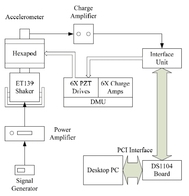
Figur e 15.6 shows the experiment setu p and the connections between various de-
vices. The Stewart platform is mounted o n a shaker ( Labworks ET139) through
a custom−made mountin g interface. The shaker is powered by a power amplifier,
which in turn is driven by a signal generator. A sine wave is used as the reference
signal for the shaker. The piezoelectric accelerometer (357B21 from PCB Piezoelec-
tronics) is placed at the center of the top p late to detect the erro r signal of t he system
as a whole. A charge amplifier (Sinocera YE5852) will amplify the detected error
signal from the accelerometer and filter the high frequency noise b efore the signal
is sent to the controller via the ADC unit. An interface unit of DS1104 DSP board,
which includes peripheral outlets for the DS1104 card, serves as a junction point
among the DSP board, charge amplifier and DMU (Drive and Monitoring Unit).
Adaptive Filtering Algorithms for Active Vibration Cont rol 28 5
15.5.3.1 Experimental results
Experiments are conducted for different frequencies of vibration. Depending on the
frequency of the disturbance (vibration) signal, an adaptation step size µ is chosen.
Recall that the step size is inversely proportional to th e reference input power; a
smaller step size µ is chosen for higher frequency since the signal power increases
as the frequency is higher.
The PZT actuator has a maximum stroke length of 50 µm. In order not to exceed
the maximum stroke length of the actuator, the vibration signal is chosen with 200
mV peak-to-peak at th e ADC input. Error signal at the input of the algorithm will be
20 mV peak-to-peak (−40 dB) due to the scaling factor of the A/D converter.
During the experiments, th e controller is observed to be able to attenuate distur-
bances with frequency up to 220 Hz. The actual resonance frequency of the sy stem
is approximately at 230 Hz. When the vibration frequency is around 230 Hz, the
system r uns into an unstable state. This may be due to a large modeling error around
the resonance frequency. Theoretically, there is a phase shift of close to 180
◦
around
the resonance frequency. The phase response of the secondary path also shows that
there is a major phase shift around the resonance frequ ency. But the phase response
in the identification result may not have sufficient changes to represent the resonance
region.
Therefore, the contr oller is modified to compensate the phase error. Inverted gain
(−1) is inserted in the error signal path and the control ler is tested with frequency
starting from 2 40 Hz. With this modification, disturbance frequency up to 280 Hz is
observed to be attenuated.
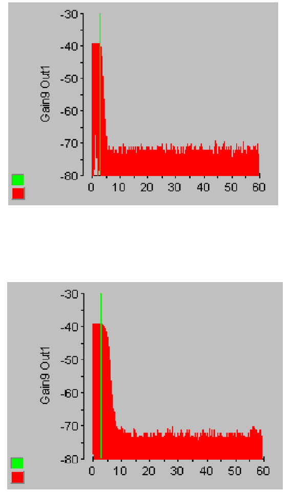
Figur es (15.7)−(15.10) are the experimental resul ts captured by dSPACE control
desk w ith frequency 60 Hz, 210 Hz, 240 Hz, and 270 Hz, respectively. The straight
line is the po int where AVC is switched on. The error signal is inverted when the
disturbance frequency is set at 240 Hz and 270 Hz.

286 Modeling and Control of Vibratio n in Mechanical Systems
FIGURE 15.6
General layout of the experimental setup.

Adaptive Filtering Algorithms for Active Vibration Cont rol 28 7
FIGURE 15.7
60 Hz error si gnal in dB unit .
FIGURE 15.8
210 Hz error signal in dB unit.

288 Modeling and Control of Vibratio n in Mechanical Systems
FIGURE 15.9
240 Hz error signal in dB unit.
FIGURE 15.10
270 Hz error signal in dB unit.
Adaptive Filtering Algorithms for Active Vibration Cont rol 28 9
15.5.3.2 Controller modification a nd discussion
Observe from Figure 15.7−Figure 15.10 that the level of vibration attenuation varies
with frequency. It may be because of the error of magni tude in the frequency re-
sponse of the secondary path. An accurate modeling is required not only at the
fundamental frequency but also at the harmonics of the disturbance signal. Because
once the controller start s to suppress the disturbance si gnal, harmonics will be intro-
duced in the r eference signal path of the controller.
Therefore, mod el ing is a big challenge. Nonlinearity of the secondary path ac-
tuator introduces modeling error and instability. Mod eling errors include magnitude
error and phase error. Phase error is a crucial factor since the feedback control system
must be able to predict the disturbance before the cont rol signal is sent o ut. Phase
error in the secondary path model of the synthesizer section will i ntroduce the wrong
phase i n the reference sign al . Then the phase error in the reference signal makes the
adaptive controller output the wrong phase of cancellation signal to the PZT actuator
as well as t o the synthesizer again.
The magnitude response of the secondary path model is altered by ± 6 dB, which
means that the FIR models of the secondary path are multiplied by 2 or d ivided by
2, to introduce the magnitude error. Then the experiments are conducted again. The
stabil ity of the controller is not affected and there is only a slight decrease in vibration
attenuation level. Furthermore, there is a magnitude peak at 2 40 Hz in the frequency
response of the secondary path model. Based on the experiments, the actual peak
response is estimated to be at 230 Hz. But the controller i s able to attenuate the
disturbance frequency of 240 Hz with the phase compensating gain (−1) in th e error
signal path. Therefore, we can say th at the adaptive feedback controller i s able to
tolerate some magnitude error in the secondary path model.
During the experiment, the controller is observed to have a faster convergence
rate for a higher frequency vibration . It verifies that a larger signal power at higher
frequency can drive the adaptive filter to converge at a faster rate. B ut the faster
convergence rate due to the higher signal power can lead the system to instability if
the adaptation step size “µ” is not sufficiently small . Minimizing the adaptation step
size can improve the stability of the controller but a slow convergence rate has to be
borne.
Another strategy used to compromise between the stability and convergence rate is
to use the normalized LMS alg orithm. The NFXLMS algorithm is able to work well
in the feedforward al gorithm. Bu t in the practical implementation of adaptive feed-
back system, surged convergence of the normalized adaptive filter is again observed
to cause some instabili ty to the feedback system.
Therefore, instead of applying the normalized algorithm, another strategy is devel-
oped and applied to the system to ensure the stability and to improve the convergence
of the adaptive algo rithm. That is an automatic gain control (AGC), introduced in
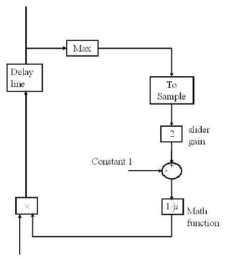
the reference signal path as sh own in Figu re 15.11.
When the adaptive controllers start to adapt their filter weights, it is observed that
the reference signal becomes larger than the normal level before th e adaptati on is
triggered. It may be because of the error of magnitude of the secondary path model.

290 Modeling and Control of Vibratio n in Mechanical Systems
In order to prevent the actuator from being overdriven and the control system from
being driven into an unstable situati on, an automatic gain control, AGC is inserted
in the reference si gnal path. AGC is a simple nonlinear attenuator. The reference
signal g enerated by the synthesizer will be t ransformed into a 16-order vector f orm
by a delay line. “Max” block will filter out the maximum value of t he vector signal
and this signal will be transformed back to a scalar value by “To Sample” block.
This scalar value is amplified with “Sli der Gain ” which can be adjusted during the
experiment to obtain the best performance. Constant value 1 is added to avoid the
division b y zero. The summed value will be reciprocated by the math fu nction “1/µ”.
This results in a variable attenuating factor for the reference signal by i nputting it to
the “Cross Product” block tog et her with the reference signal. Therefore, when the
reference signal becomes larger, AGC will attenuate more and maintain the reference
signal within a safe level. The mathematical description of the automatic gain control
is
X
o
(k + 1) =
X
i
(k + 1)
1 + gX
o
(k)
, (15.2 6)
where g is the AGC gain (slider gain).
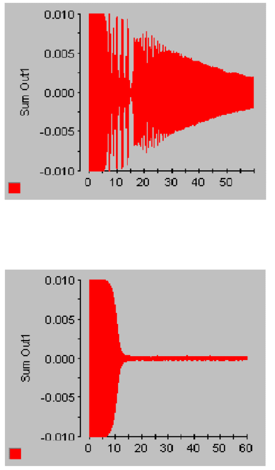
The different resul ts between with and without auto matic gain control are shown
Figur es 15.12 and 15.13. It can be seen that automatic gain control can greatly
improve the performance of the adaptive feedback controller. Another way of min-
imizing the overgrowing of reference signal is to restrict the adaptive filter weights
by putting in a leakage factor. The leakage factor o f the adaptive filter prevents the
weight vector from growing without bound after the convergence of the error signal.
A leakage factor of abo ut 0.9999 is chosen so that 1 − 0.9999 = 0.0001 is still less
than the smallest adaptation size 0.0005 in the experiments. B ut experi ments with
the leakage factor show that the attenuation level is decreased from 30 dB to 20 dB.
Although the leakage factor can improve the stability, it can degrade the performance
of the AVC.
15.6 Co nclusion
In this chapter, with the adaptive filtering algorith m being conceptualized, a multiple-
reference adaptive feedback controller h as been developed. A 6×1 adaptive feedback
system has been implemented using Si mulink and Control Desk. Adaptive ident ifi-
cation has been used to model the six PZT actuators in the secondary path.
Experiments have been performed with different adaptation step µ. Lower step
size has t o be chosen for a high frequency vi bration signal in order to take into
account its high sign al power. Impro perly chosen µ has been observed to affect the
stabil ity and performance of the control system.
The regenerated reference signal has been observed to become larger than the nor-
mal level before the adaptive filter has started to adapt. The leaky FXLMS algor ithm

Adaptive Filtering Algorithms for Active Vibration Cont rol 29 1
has been appli ed to restrict the overflow of the weig ht vector of the adaptive filter. But
the controller performance is degraded with introdu ci ng the leakage factor. Finally
the automatic gain controller has been considered and developed in the reference sig-
nal path. The experimental results are greatly improved by fine-tuning the slider gain
of the automatic gain controller. Actually, the nonlinear property of the auto matic
gain controller partially compensates for the modeling error so that the performance
and stability of the adaptive feedback controller are comparatively b et ter than those
without using the automatic gain controller. For vibrations wi th frequencies fro m 60
to 22 0 Hz, an attenuation level of up to 30 dB has been achieved. Therefore, the
adaptive feedback controller can provide satisfactory performance among various
constraints.
FIGURE 15.11
Simulink diagram of automatic gain control.

292 Modeling and Control of Vibratio n in Mechanical Systems
FIGURE 15.12
180 Hz error signal without automatic gain control.
FIGURE 15.13
180 Hz error signal with automatic gain control.

References
[1] S. Deeyiengyang, and K. Ono, “Suppression of resonance amplit ude
of disk vibration s by squeeze air bearing plate,” IEEE Trans. Magnet-
ics, vol. 37, no . 2, pp. 820−825, 200 1.
[2] B. A. Fr ancis, and J. C. Doyle, “Linear control theory with an H
∞
optimality criteron,” SIAM J. Control and Optimi zation, vol. 25, pp.
815−844, 1987.
[3] S. Boyd, and C. A. Desoer, “Subharmonic functions and performance
bounds in l inear time-invariant feedback systems,” IM A J. Mathemat-
ical Control and Information, vol. 2, pp. 153−170 , 1985.
[4] D. E. Baxa and R. A. Dykstra, “Pneumatic isolati on systems control
forging hammer vibration,” Sound and Vibration, vol. 14, pp. 22−25,
1980.
[5] A. Soon and M. -S. Lee, “Optimal d esign of linear and nonlinear ab-
sorbers for damped systems,” Journal of Vibration, Acoustics, Stress,
and Reliability in Design, vol. 105, p p. 112−119, 1983.
[6] K. Zhou, J. C. Doyle, Essentials of Robust Control, Prentice Hall Inc.,
1998.
[7] Ali Saberi, P. Sannuti, B. M. Chen, H
2
Optimal Control, Prentice Hall
Inc., 1995.
[8] T. Krysi nski, F. Malburet, Mechanical Vibrations: Active and Passive
Control, ISTE Ltd, 200 7.
[9] S. S. Rao, Mechanical Vibrations, Addison-Wesley Publishing C om-
pany, 19 90.
[10] Guzik Company Website [Online], Spin Stand Products Information,
http:/ /www.guzik.com.
[11] B. Heo, I. Y. Shen, “Taming disk and spindle rocking by damped lam-
inated disks − an experimental study,” IEEE Trans. Magnetics, 35(5),
pp. 2304−2306, 1999.
[12] C. Du, G. Guo and D. Wu, “Low-hump sensitivity function design for
dual-stage systems with different micro actuators,” IEE Proc. Control
Theory and Applicatio n, 152(6), pp. 655−661, 2005.
293
