Du C., Xie L. Modeling and Control of Vibration in Mechanical Systems
Подождите немного. Документ загружается.


254 Modeling and Control of Vibratio n in Mechanical Systems
10
1
10
2
40
60
80
100
10
1
10
2
−300
−200
−100
0
Frequency(Hz)
Phase (deg)
Magnitude(dB)
0.25V
0.5V
FIGURE 13.4
Actuator frequency responses with friction compensation for different displacements
in voltage wi th 0.5µm/V (St raight smooth lines: the pure double integrator).
10
1
10
2
40
60
80
100
10
1
10
2
−300
−200
−100
0
Frequency(Hz)
Phase (deg)
Magnitude(dB)
1V
3V
FIGURE 13.5
Actuator frequency responses with friction compensation for different displacements
in voltage wi th 0.5 µm/V (Straight smooth lines: th e pure double i ntegrator).
Nonlinearity Comp ensation and Nonlinear Control 255
10
1
10
2
10
3
−90
−80
−70
−60
−50
−40
−30
−20
−10
0
10
After compensation
After compensation
Before compensation
Magnitude(dB)
Frequency(Hz)
FIGURE 13.6
Sensitivity functions with and without friction compensation.
as observed from the well known Bode integral constraint. For example, the KYP
Lemma-based control design in Chapter 8 results in an excellent attenuation of dis-
turbance around 650 Hz. But its abi lity in rejectin g low frequency disturbance is
not very desirable. On the other hand, in Chapter 2, the low-frequency disturbance
is modeled as the output of an adaptive nonl inear scheme w ith the error sign al as
the input. Here it is used to compensate for the low-frequency disturbance, i.e., a
nonlinear controller is augmented with the KYP Lemma-based linear feedback con-
troller, which remarkably improves the syst em dist urbance rejection capability in
low frequency range without sacrificing performance at o ther frequencies.
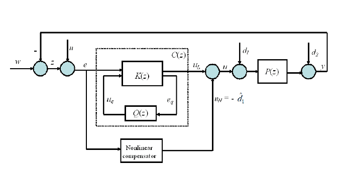
Considering Figure 13.7 with plant P (z): (A
p
, B
p
, C
p
, D
p
), we have the f ol-
lowing discrete time state-space realization:
x(k + 1) = A
p
x(k) + B
p
u(k) + B
p
d
1
(k), (13.1)
z(k) = −C
p
x(k) + w(k) − D
p
u(k) − D
p
d
1
(k) − d
2
(k), (13.2)
e(k) = −C
p
x(k) + w(k) − D
p
u(k) − D
p
d
1
(k) −d
2
(k) + n(k). (13.3)
The design of control law u = u
L
+ u
N
includes t w o parts:
1. The first is to design a linear dynamic output feedback controller u
L
= C(z)e
for t he plant P (z) such that t he closed-loop syst em is stable and satisfies the
performance in (8.2).
256 Modeling and Control of Vibratio n in Mechanical Systems
FIGURE 13.7
Control structure of a plant P (s) with Youla parametri zati on approach and adaptive
nonlinear compensation.
2. The second is to design a nonlinear contr ol l aw u
N
such that the contribution
of the low-frequency disturbance in d
1
to the error can be compensated.
13.3.1 Design of a composite control law
The linear con trol law design based on the KYP Lemma in Chapter 8 can give goo d
rejection of dist urbance of particular frequencies such as that around 650 Hz. How-
ever, the performance at low frequency needs to be improved. Thus we shall design a
nonlinear compensation based on the nonlinear modeling discussed in Section 2.4.2.
Note that the modeling in Section 2.4.2 is based on the time history of the mea-
surement e. We consider the modeled distur bance
ˆ
d
1
given by
ˆ
d
1
= ˜ω
T
(k)s(Φ
k
) (13.4)
with the update law
˜ω(k + 1) = (1 − δ)˜ω(k) − Γs(Φ
k
)e(k), (13.5)
where s(Φ
k
) is given in (2.56).
As demonstrated later, by injecting
u
N
(k) = −
ˆ
d
1
(13.6 )
to the plant combined with u
L
as shown in Figure 13.7, we are able t o compensate
the low-frequency disturbance in d
1
, which is modeled as in (2.55).

Nonlinearity Comp ensation and Nonlinear Control 257
13.3.2 Experimental results in hard disk drives
The pl ant under consideration and the linear control ler are the same as in Section
8.6 of Chapter 8. The nonlinear control signal u
N
in Fi gure 13.7 is calculated from
(13.5)−(13 .6) and (2.56) in Section 2.4.2 of Chapter 2. The center positio ns c
e
i
and
c
∆e
i
for the measurement e and velocity ˙e are chosen as zero. The variances are
σ
2
e
i
= σ
2
∆e
i
= 10, i = 1, ..., p . The forgetting factor δ = 0.5. Γ affects the learning
speed and should be selected to b e as large as possible.
To evaluate the disturbance rejection performance o f the combined linear cont rol
C(z) designed in Section 8.6 in Chapter 8 and the nonlinear control (13.6), a sinu-
soidal signal with the logarithmically spaced frequency f rom 10 Hz to 22.5 kHz is
respectively injected as w in Figure 13.7. For each frequency sinusoidal i nput, the
error signal e will involve multiple frequency components due to the nonlinear con-
trol. In this situation, it is reasonable that the error rejection capabilit y is directly
measured as the amplitude ratio e/w in time domain. At each frequency point, the
error rejection e/w is then plotted and shown in Figure 13.8.
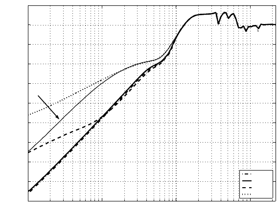
The error rejection capability is evaluated for each value o f p = 1, 5, 9. As in
Figur e 13.8, the two cases with p = 1 and p = 5 give similar results, and bo th are
better than that given by p = 9. This implies that a higher p may not necessarily
lead to a better result. This phenomenon i s consi stent with the observation in mod-
eling. Overall, from the simulation result, the nonlinear control pr oduces a better
rejection of disturbances of low frequencies, while not affecting t he high frequ ency
disturbance rejection performance.
Figur e 13 .8 also shows the effect of Γ on the error rejection. 10% of the Γ value
in (2.58) is used in the calculation. It is observed that the larger Γ yields a better
accuracy. This also agrees with the modeling result in Section 2.4.2 in Chapter 2 .
Consequently, corresponding to the error rejection i n Figure 13.8 with p = 1, the
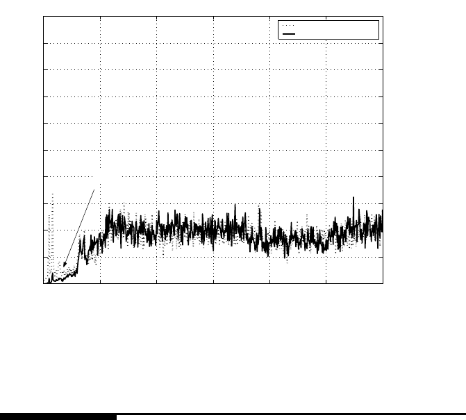
power spectrum of PES NRRO is shown in Fig 13.9. It is observed that the error
is much lowered by 8 0% before 400 Hz, and no cost in higher frequency range is
paid. Overall it is evaluated from calculation that the 3 σ of the true PES NRRO
is improved from 6.0 nm with the KYP Lemma method to 5.5 nm with the KYP
Lemma-based li near cont rol augmented with the nonlinear control.
REMARK 13.1 It should be mentioned tha t the nonlinear compensation
scheme can b e combined with any l inear control to improve low frequency
vibratio n rejection without sacrificing disturbance rejection capability in other
frequency ranges.
258 Modeling and Control of Vibratio n in Mechanical Systems
10
1
10
2
10
3
10
4
−90
−80
−70
−60
−50
−40
−30
−20
−10
0
10
p=1
p=5
p=9
No u
N
Magnitude(dB)
Frequency(Hz)
0.1Γ
FIGURE 13.8
Comparison of error rejection frequency response without and with u
N
of different
p and Γ.
Nonlinearity Comp ensation and Nonlinear Control 259
0 1000 2000 3000 4000 5000 6000
0
0.1
0.2
0.3
0.4
0.5
0.6
0.7
0.8
0.9
1
x 10
−3
KYP
KYP+nonlinear control
NRRO magnitude(µm)
Frequency(Hz)
400 Hz
FIGURE 13.9
NRRO power spectrum with KYP lemma-based linear control and nonlinear com-
pensation (80% reduction before 400 Hz).
13.4 Co nclusion
The nonlinear friction has been compensated for by injecting the modeled friction
force in Chapter 2 into the actuator. With the model based compensation, the lin-
earization effect for the VCM actuator has been verified via the measurement of the
hysteresis in time domain and the frequency response in frequ ency domain. The
measured error rejection function showed an increased error rejection capability in
low frequency range, as a result of the compensation.
To further improve the disturbance rejection in low frequency range, the linear
control is combined with an adaptive non linear compensatio n. The simulation results
have demonstrated that the proposed controller can effectively reject disturbances at
low frequencies, resulting in a marked improvement for the 3σ value of the PES
NRRO in the data stor age system.

14
Quantization Effect on Vibration Rejection
and Its Compensation
14.1 Introduction
A/D and D/A converters are inevitable in digital control systems. Chapter 5 men-
tioned quantizatio n performed by the A/D converter. This chapter investigates the
quantization effect on vibration rejection capabilit y of the closed-loop control sys-
tem. With a proposed quantizer model, the influence of d ifferent quantizer bits on
the error rejection ability in low frequency range is analyzed and evaluated based
on frequency response measurement. On the ot her hand, it is known that nonlinear
behavio rs such as actuator pivot friction limit the low frequency gain of the open
loop. Translated to the error rejection function or sensitivity functio n, it lifts the
magnitude at low frequencies and thus r educes the ability of the closed-loop system
to reject vibrations in the low frequency range. Therefore, quantization and friction
induced problems sh ould be treated differently for more effective control .
A simple and low cost scaling scheme is developed in this chapter to compen-
sate for the effect of the quantizer. It is demonstrated that the compensation scheme
is effective in improving the sensitivity fu nction in the low frequency range with -
out deteriorating performances at other frequencies. With the compensation for the
quantization effect, the impact on the rejection ability is mostly due to the friction.
As such, the effects from quantization and friction o n th e error rejection function can
be differentiated, and the quantization and friction induced problems can be tack-
led separately in the con trol loop. Additionally, t hrough the proposed quantization
model and measurement methodology, suitable bit resolution for the quantizer can
be identified with and without the compensation .
14.2 Description of control system with quantizer
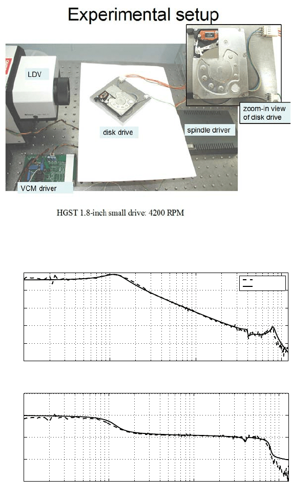
The system under investigation is the VCM actuato r in a commercial 1.8−inch d isk
drive with a spindle motor rotational speed of 4200 RPM. The experiment setup is
shown in Figure 14.1, wh ere the spindle dr iver is used to spin the spindle motor, the
261

262 Modeling and Control of Vibratio n in Mechanical Systems
LDV is to measure the positio n of the read/write head, and a VCM driver to drive
the VCM actuator. The LDV d isplacement range is set as 2 µm/V. The frequency
response of the VCM actuator is measured via DSA by injecting a swept sine wave
of 5 mV amplitude. Due to experimental limitations, measurements in this chapter
are taken when the head is positioned in the middle-diameter region of the disk. The
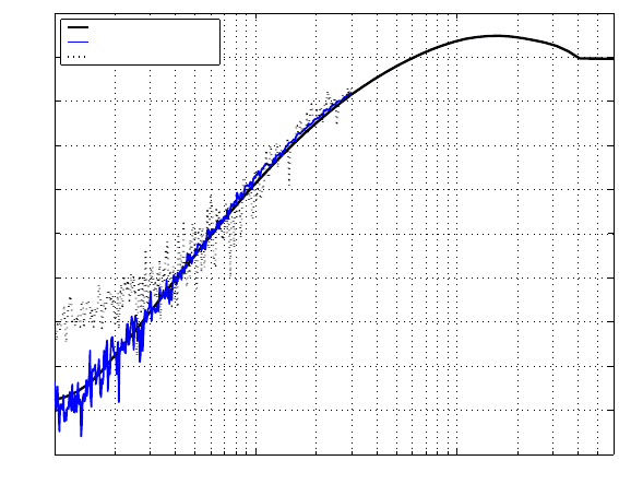
measured frequency response of t he VCM actuator is shown in Figure 14.2, and its
model P (s) is obtained as
zeros = 10
5
× [1.6 965; −0.0077 ± 0.2575j];
poles = 10
5
× [−1.6965; −0.0251 ± 0.5020j;
−0.0101 ± 0.2511j; −0.0019 ± 0.0073j];
gain = −5.3167 × 10
17
.
A PID con troller combined with notch filters is designed for the VCM actuator and
shown in Figure 14.4. The clo sed servo loop o f the VCM actuator is seen in Figur e
14.3, where dSpace DS1 103 with TMS320C 240 DSP on board are used to imple-
ment the con troller with the sampling rate of 30 kHz. The quantizer model Q(·) is
given by
Q(e) =
max(e)
2
n
× floor
e ×
2
n
max(e)
+ 0.5
, (14.1 )
where n is t he quantizer bit , max(e) means th e maximum amplitude of the error
signal e, and floor(e) means rounding e to the nearest integer towards minus infinity.
The sensitivity function o f the control loop without Q(e) i s given by
S(z) =
1
1 + P (z)C(z)
. (14.2)
A swept sine wave with 50 mV amplitude is injected as the reference signal to t he
closed control loop and the sensitivity function S(z) is measured and plotted in Fig-
ure 14.5. It is known that as t he excitation level to th e VCM actuator decreases, the
VCM actuator gain in the low frequency range is lowered due to friction nonlinearity
effect [40], which correspondingly leads to the increased |S(z)|. This is illustrated
also in Fig ure 14.5, where S(z) changes for different reference amplitudes. In this
chapter, we focus on the effect of quantizer (14.1) on the sensitivity function and
seek to differentiate the quantization and friction nonlinearity effect.
With t he quantizer Q(e), the sensit ivity function is given by
S
Q
(z) =
e
reference
=
1
1 + P (z)Q
e
(z)C(z)
(14.3 )
where
Q
e
(z) =
e
3
(z)
e(z)
(14.4 )
stands for an approximation o f the quantizer (14.1).
Quantization Effect on Vibration Rejection and Its Compensation 263
FIGURE 14.1
Experimental setup.
10
1
10
2
10
3
10
4
−40
−20
0
20
40
60
Magnitude(dB)
Measured
Modeled
10
1
10
2
10
3
10
4
−600
−400
−200
0
200
Frequency(Hz)
Phase(deg)
FIGURE 14.2
Frequency response of the VCM actuator measured by i njecting a swept sin e wave
of 5mV ampli tude.
