Du C., Xie L. Modeling and Control of Vibration in Mechanical Systems
Подождите немного. Документ загружается.

184 Modeling and Control of Vibratio n in Mechanical Systems
9.2 Problem formulation
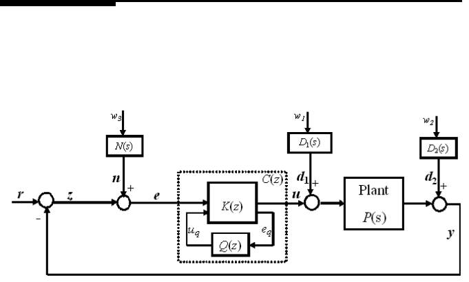
FIGURE 9.1
H
2
control scheme with Q parametrization for controller design.
In the previou s chapter, specifications on sensitivity funct ion S(z) are described
as
|S(f
i
)| < r
i
, f
i1
< f
i
< f
i2
, i = 1, 2, ···, m (9.1)
where r
i
< 1 is a positive scalar, and f
i1
and f
i2
define the f requency range.
Such an upper-bound specification as in (9.1) will lead to a problem when the fre-
quency f
i
is larger than and especially n ear th e desired bandwidth or 0-dB crossover
frequency of S(z). The 0-dB crossover frequ ency of S(z) will be pushed away to-
wards a higher frequency, as seen in Figure 9.9, which tends to damage the system
stabil ity and det eriorate the system high-frequency perfor mance. In view of this, a
lower-bound specification, i.e.,
|S(f
i
)| ≥ 1, f
i1
≤ f
i
≤ f
i2
(9.2)
is required. This specification helps to fix the bandwidth or 0 -dB crossover frequency
of S(z), which will be seen later in the appl ication results.
The problem of the specific disturbance rejection can b e solved by imposing such
performance specifications in (9.1) and then using the KYP Lemma-based control
design method in Chapter 8. However, as shown in Figure 9.1 associated with Fig-
ure 8.14, th e servo mechanical system suffers from vari ous kinds of distur bances
and sensing noise. The KYP Lemma-based control design cannot include all dis-
turbances and noises which contribute to the position error. In view of this, we also

Combined H
2
and KYP Lemma-Based Control Design 185
take into account the overall perfor mance of the servo control system, which is repre-
sented as t he so- call ed track misregistration (TMR) induced by w =
w
1
w
2
w
3
T
passing through D
1
(s), D
2
(s), and N (s). I t is expressed by the standard deviation
σ
z
of z, and
kT
zw
k
2
= σ
z
, (9.3)
when w is a white noise with zero mean and identity covariance matrix, where T
zw
is the transfer function from w to z.
In the next section, we proceed to the controller design to achieve the specifica-
tions in (9.1) and (9.2), and meanwhil e to optimize (9.3).
9.3 Controller design for specific disturbance rejection and over-
all error minimization
The generalized KYP Lemma-based design method in Chapter 8 is used to design a
controller for specific disturbance at tenuation.
Let (A
p
, B
p
, C
p
, D
p
) and (A
c
, B
c
, C
c
, D
c
) respectively be the state-space model
of plant P (z) and controller C(z). In order to convexify matri x inequalities, the
Youla parametrization approach with the Q(z) in a FIR filter form is app lied and the
controller structure is shown in Figure 9.1. K(z) is an observer based controller that
can be designed using the LQG method as in (8.11)−(8.12).
For the presentation of the KYP Lemma, we denote
σ(S, Π) :=
S
I
∗
Π
S
I
(9.4)
where S(z) = S(e
jθ
), I stands for an identity matrix and Π a Hermiti an matrix of
the form
Π =
Π
11
Π
12
Π
∗
12
Π
22
, (9.5)
which specifies the frequency domain property to be investigated.
9.3.1 Q parametrization to meet specific specifications
A. Specification (9.1)
Recall from (8.13)−(8.14) that a set of sensitivity functions S(z): (
˜
A,
˜
B,
˜
C,
˜
D)
can be Q-parameterized.
According to the denotation (9.4)−(9.5), the specification |S(z)| ≤ r is written as
σ(S, Π) ≤ 0 with
Π =
Π
11
Π
12
Π
∗
12
Π
22
=
1 0
0 − r
2
. (9.6)
186 Modeling and Control of Vibratio n in Mechanical Systems
Thus based on t he KYP Lemma in Chapter 8, achieving
S
e
jθ
≤ r for the
frequency range θ
1
≤ θ ≤ θ
2
can be obtained by solving the following matrix
inequality
˜
A
˜
B
I 0
∗
Σ
˜
A
˜
B
I 0
+
˜
C
˜
D
0 I
∗
Π
˜
C
˜
D
0 I
≤ 0, (9.7)
which is, since Π
11
> 0, equivalent to
˜
A
˜
B
I 0
∗
Σ
˜
A
˜
B
I 0
+
0 0
0 −r
2
˜
C
˜
D
∗
Π
11
Π
11
˜
C
˜
D
−Π
11
≤ 0, (9.8)
where
Σ =
−U e
jθ
c
V
e
−jθ
c
V U −(2 cos θ
d
) V
, (9.9)
θ
c
=
(θ
1
+ θ
2
)
/
2
, θ
d
=
(θ
2
−θ
1
)
/
2
, (9.10)
U and V are Hermiti an matrices and V ≥ 0.
To convexify the matrix inequality (9.8), we shall give a state space realization
of S(z) = T
11
(z) + T
12
(z) Q (z) T
21
(z). Denote the state-space representation
of T
11
(z) and T
12
(z)T
21
(z) by (A
t11
, B
t11
, C
t11
, D
t11
) and (A
t
, B
t
, C
t
, D
t
),
respectively. Then a state-space model of S(z) can be written as (8.17)−(8.18).
B. Specification (9.2)
Again, accordin g to the denotation (9.4)−(9.5) th e specification |S(z)| ≥ r is
equivalent to σ(S, Π) ≤ 0 with
Π =
Π
11
Π
12
Π
∗
12
Π
22
=
−1 0
0 r
2
. (9.11)
However, because Π
11
< 0, (9.7) can not be converted equivalently to (9.8), which
means (9.7) is not possibly convexified according to the method i n Section 9.3.1.
Hence we resort to the following specification
σ (S, Π) = aR(S) + bI (S) + c, Π :=
0 a + jb
a − jb 2c
(9.12 )
where R and I denote the real and the imaginary parts o f S(e
jθ
). When a, b and
c are properly selected, |S(z)| ≥ r can be achieved. A simple selection is a = 0,
b = −1, c = r, and
σ (S, Π) = −I (S) + r. (9.13)
Thus σ(S, Π) ≤ 0 means I (S) ≥ r, and subsequently |S(z)| ≥ r. In this situation,
Π =
Π
11
Π
12
Π
∗
12
Π
22
=
0 −j
j 2r
, (9.14 )
Combined H
2
and KYP Lemma-Based Control Design 187
where Π
11
= 0 and (9.7) is equivalent to
˜
A
˜
B
I 0
∗
Σ
˜
A
˜
B
I 0
+
0
˜
C
∗
Π
12
Π
∗
12
˜
C
˜
D
∗
Π
12
+ Π
∗
12
˜
D + Π
22
≤ 0, (9.15)
which is a linear matrix inequali ty with unknown variables in
˜
C and
˜
D only, and can
be solved usi ng the same method as in Section 9.3.1A.
It should be mentioned that R(S) ≥ r can also be used to achieve |S(z)| ≥ r, if
it is suitable for a specific application. In this case,
Π =
Π
11
Π
12
Π
∗
12
Π
22
=
0 −1
−1 2r
, (9.16 )
and the linear matrix i nequality (9.15) remains applicable.
9.3.2 Q parametrization to minimize H
2
performance
Next we focus on the design of Q(z) to minimize the H
2
norm kT
zw
k
2
. From Fi gure
9.1 we have
−z = N (z) w
3
+ S (z) [P (z) D
1
(z) w
1
+ D
2
(z) w
2
−N (z) w
3
] . (9.17)
Denote a state-space realization of P (z)D
1
(z), D
2
(z) and N(z) by (A
1
, B
1
, C
1
, D
1
),
(A
2
, B
2
, C
2
, D
2
), and (A
3
, B
3
, C
3
, D
3
), respectively. It follows from (8.13) and
(8.17)−(8.18) that
x (k + 1) =
¯
Ax (k) +
¯
Bw(k), (9.18)
−z (k) =
¯
Cx (k) +
¯
Dw(k), (9. 19)
where,
¯
A =
A
1
0 0 0
0 A
2
0 0
0 0 A
3
0
˜
BC
1
˜
BC
2
−
˜
BC
3
˜
A
,
¯
B =
B
1
0 0
0 B
2
0
0 0 B
3
˜
BD
1
˜
BD
2
−
˜
BD
3
, (9. 20)
¯
C =
˜
DC
1
˜
DC
2
−
˜
DC
3
+ C
3
˜
C
,
¯
D =
˜
DD
1
˜
DD
2
−
˜
DD
3
+ D
3
.
The H
2
norm kT
zw
k
2
can be minimized as follows:
min
(Ξ=Ξ
T
>0, Ω=Ω
T
>0)
T race (Ω) (9.21)
subject to
¯
A
T
Ξ
¯
A −Ξ +
¯
C
T
¯
C < 0 (9.22)
¯
B
T
Ξ
¯
B +
¯
D
T
¯
D < Ω (9.23)
188 Modeling and Control of Vibratio n in Mechanical Systems
or equivalently,
¯
A
T
Ξ
¯
A − Ξ
¯
C
T
¯
C −I
< 0 (9.24)
−Ω +
¯
B
T
Ξ
¯
B
¯
D
T
¯
D −I
< 0 (9.2 5)
where
¯
A =
A
1
0 0 0 0 0
0 A
2
0 0 0 0
0 0 A
3
0 0 0
B
t11
C
1
B
t11
C
2
−B
t11
C
3
A
t11
0 0
B
t
C
1
B
t
C
2
−B
t
C
3
0 A
t
0
B
q
D
t
C
1
B
q
D
t
C −B
q
D
t
C
3
0 B
q
C
t
A
q
,
¯
B =
B
1
0 0
0 B
2
0
0 0 B
3
B
t11
D
1
B
t11
D
2
−B
t11
D
3
B
t
D
1
B
t
D
2
−B
t
D
3
B
q
D
t
D
1
B
q
D
t
D
2
−B
q
D
t
D
3
,
¯
C =
(D
t11
+ D
q
D
t
) C
1
(D
t11
+ D
q
D
t
) C
2
(D
t11
+ D
q
D
t
) C
3
C
t11
D
q
C
t
C
q
,
¯
D =
(D
t11
+ D
q
D
t
) D
1
(D
t11
+ D
q
D
t
) D
2
−(D
t11
+ D
q
D
t
) D
3
+ D
3
] . (9.2 6)
Note that the Q(z) coefficients q
i
(i = 0, 1, . . . , τ) only appear in C
q
and D
q
.
Therefore, from (8.17)−(8.18) and (9.26), we know that q
i
exists only in
˜
C,
˜
D,
¯
C
and
¯
D. In this case, (9.8), (9.15) and ( 9.24)−(9.25) define LMIs in terms of the
variables U, V , Ξ, Ω and q
i
. Hence, the Q(z) coefficients q
i
can be computed via a
convex optimization.
With t he solved Q(z): (A
q
, B
q
, C
q
, D
q
), t he controller C(z) is then given by
A
c
=
A
p
−B
p
M + LC
p
+ B
p
D
q
C
p
B
p
C
q
B
q
C
p
A
q
,
B
c
=
L + B
p
D
q
B
q
,
C
c
=
−M + D
q
C
p
C
q
,
D
c
= D
q
.
(9.27 )
9.3.3 Design steps
To summarize, a design procedure for con troller C(z) is given as foll ows.

Combined H
2
and KYP Lemma-Based Control Design 189
Step 1. Design K(z) from (8.11)−(8.12).
Step 2. Compute T
11
(z), T
12
(z) and T
21
(z) from (8.14), and obtain the state space
model (
˜
A,
˜
B,
˜
C,
˜
D) i n (8.17)−(8.18).
Step 3. Based on disturbance spectrum and bandwidth requirement, specify the
positive scalars r
i
and r
j
, and the frequency point s f
i
(i = 1, . . ., m) and f
j
(j = 1,
. . . , n) for the sensitivity function S(z), i.e.,
|S (f
i
)| < r
i
, f
i1
≤ f
i
≤ f
i2
, (9. 28)
and
|S (f
j
)| > r
j
, f
j1
≤ f
j
≤ f
j2
. (9.29 )
For each specification, const ruct the LMIs (9.8) and (9.15) in terms of the variables
U, V , C
q
and D
q
.
Step 4. Construct the LMIs (9.24)−(9.25) in terms of the variables Ξ, Ω, C
q
and
D
q
.
Step 5. Obtain Q(z) : (A
q
, B
q
, C
q
, D
q
) by solving the above LMIs using the
MATLAB LMI to olbox.
Step 6. Obtain the controller C(z) from (9.27).
9.4 Simulation and implementation result s
This section will apply the control design method in Section 9.3 f or a PZT microac-
tuator to separately reject one or two specific disturbances and meanwhile minimize
the H
2
norm of the PES.
9.4.1 System models
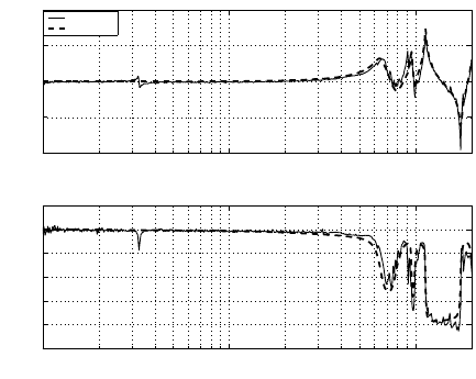
The frequency response of the PZT microactuator, shown in Figure 9.2, was obtained
using a LDV and a DSA. The main resonance modes of the plant are at frequencies
6.5 kHz, 9.5 kHz, 11.3 kHz, and 20 kHz. The identified pl ant model of th e micro-
actuator P (s) has the following parameters:
Zer os = 10
5
× [−0.0296 ± 0 .4927j, − 0.0110 ± 1.0964j,
− 0.7116 ± 0.6275 j, − 0.0093 ±0.6198j, 0.8168],
P oles = 10
5
×[−0.0255 ±1.2733j, − 0.0050 ± 0.7100j,
− 0.0048 ± 0.5981 j, − 0.0245 ±0.4071j, − 0.8168],
Gain = −0.4819.
The frequency response of the plant model is plotted against the measured data in
Figur e 9.2 for comparison and it is subsequently discretized in MATLAB using the
“zoh” method with a sampling rate of 40 kHz.
190 Modeling and Control of Vibratio n in Mechanical Systems
10
2
10
3
10
4
−40
−20
0
20
40
Frequency (Hz)
Magnitude (dB)
10
2
10
3
10
4
−250
−200
−150
−100
−50
0
50
Frequency (Hz)
Phase (deg)
Measured
Modeled
FIGURE 9.2
Frequency response of a PZT microactuator.
9.4.2 Rejection of specific disturbance and H
2
performance minimiza-
tion
Consider the disturbances in Figure 8.14; the disturbance around 650 Hz is due to
the disk vibration. A suitable feedback controller, C(z) has to be designed for the
system so th at the overall system is stable and the disturbance around 650 Hz is
suppressed su fficiently, while ensuring that the H
2
norm of the position error signal
is minimized. Hence, the desired specification of the sensitivity functi on S(z) is
|S ( f)| < −10 dB for 610 Hz ≤ f ≤ 670 Hz and at the same time the position error
signal is to be minimized.
The parameters of a fir st-order FIR Q(z) are obtained b y solving the three LMIs
(9.8), (9.24) and (9.25). For comparison, another controller is designed without H
2
minimization and just to suppress the vibration around 650 Hz. With each of the
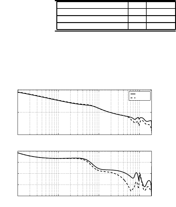
two designed controllers, the frequ ency response of the open-loop C(z) ×P (z) and
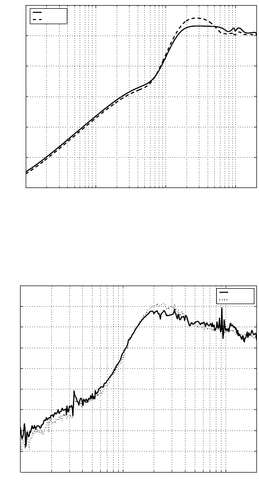
the sensitivity function S(z) are depicted in Figure 9.3 and Figure 9.4. It is seen
that the hump of S(z) is reduced to about 3 dB with the controller designed by
the combined method, i.e., the combined H
2
optimization and specific disturbance
rejection method. On the other hand, the performance sp ecifications listed in Table
9.1 show that the proposed method offers better stabilit y margins although the open-
loop crossover frequency is a bit lower.
Experiments are carried out for the KYP Lemma-based controller and the KYP+H
2
controller to verify the simulation results. The controllers are implemented using
dSPACE 1103 on a TMS320C240 DSP board and the st ructure of the experimental
setup is the same as in Figure 8.10. The sensitivity function of the system is obtained
by the rati o of the measurements in Channel 2 and Channel 1 o f the DSA, where a
swept sine signal is the reference input. The sensitivity f unction obtained from the
Combined H
2
and KYP Lemma-Based Control Design 191
TABLE 9.1
Comparison of performance specifications
Method KYP KYP+H
2
Crossover frequency (kHz) 1.85 1.78
Gain margi n (dB) 7.9 1 2.6
Phase margin (deg) 35.4 45.9
experiment, as shown i n Figure 9.5, demonstrates th e effectiveness of the proposed
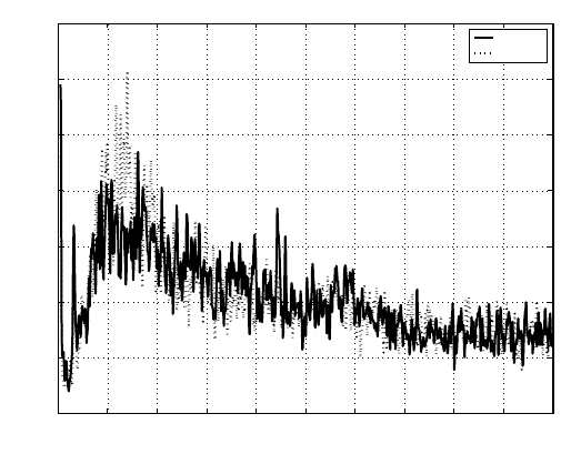
method. As a result, as seen in Figure 9.6, the position error is reduced and its σ
value has a 4% improvement .
10
1
10
2
10
3
10
4
−50
0
50
Magnitude(dB)
10
1
10
2
10
3
10
4
−250
−200
−150
−100
−50
Phase(deg)
Frequency(Hz)
KYP+H
2
KYP
Frequency(Hz)
FIGURE 9.3
Open-loop frequency responses.
192 Modeling and Control of Vibratio n in Mechanical Systems
10
1
10
2
10
3
10
4
−50
−40
−30
−20
−10
0
10
Magnitude(dB)
Frequency(Hz)
KYP+H
2
KYP
FIGURE 9.4
Designed sensitivity functions.
10
2
10
3
10
4
−35
−30
−25
−20
−15
−10
−5
0
5
10
Frequency (Hz)
Magnitude (dB)
KYP+H
2
KYP
FIGURE 9.5
Comparison of sensitivity functions obtained from experiment.
Combined H
2
and KYP Lemma-Based Con trol Desig n 193
0 0.2 0.4 0.6 0.8 1 1.2 1.4 1.6 1.8 2
x 10
4
0
0.05
0.10
0.15
0.20
0.25
0.30
0.35
Frequency (Hz)
NRRO magnitude (nm)
KYP+H
2
KYP
FIGURE 9.6
NRRO power spectrum with KYP Lemma-based controller with and without H
2
minimization.
9.4.3 Rejection of two disturbances wi th H
2
performance minimiza-
tion
In what follows, we include one more specific disturbance rejection at 2 kHz (see
Figure 9.7), which is caused by air flow and is near the desired servo bandwidth 1
kHz. In this case, the specifications on S(z) are set as:
i. |S (f)| < −10 dB for 610 Hz ≤ f ≤ 670 Hz;
ii. |S (f)| < −5 dB for 1950 Hz ≤ f ≤ 2050 Hz;
iii. |S (f)| > 0 dB for 990 Hz ≤ f ≤ 1010 Hz,
where in addition to the rejection of disturbance at 650 Hz, the disturbance around
2 kHz i s also to be suppr essed. Note that the third specification aims to fix the
bandwid th.
By solving the LMIs (9.8), (9.15) and (9.24)−(9.25) in terms of the variables
P , V , Ξ, Ω, C
q
and D
q
, a con trol ler C(z) which leads to the S(z) satisfying the
specifications can be obtained with a fou rth-o rder FIR Q (z). With the result ant
controller, t he open-loop frequency response and the sensitivity function are shown
in Fi gures 9.8 and 9.9, where the specifications (i), (ii) and (iii) have been achieved
and the closed-loop system remains stable. The open-loop gain and phase margins
are 14.6 dB and 49.5 degrees, respectively.
We have also carried out experiments to verify the designed controller. The ex-
perimental result s of the open-loop frequency response and sensitivity function are
