Du C., Xie L. Modeling and Control of Vibration in Mechanical Systems
Подождите немного. Документ загружается.


174 Modeling and Control of Vibratio n in Mechanical Systems
10
1
10
2
10
3
10
4
−50
−40
−30
−20
−10
0
10
Frequency(Hz)
Magnitude(dB)
Before KYP design
After KYP design
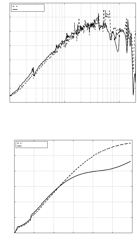
FIGURE 8.8
Sensitivity functions before and after the KYP lemma-based desig n: simulat ion re-
sult.

Generalized KYP Lemma-Based Loop Shaping Control Design 175
10
1
10
2
10
3
10
4
−20
−10
0
10
20
30
40
50
Magnitude(dB)
After KYP optimization
Before KYP optimization
10
1
10
2
10
3
10
4
−800
−600
−400
−200
0
Phase(deg)
Frequency(Hz)
FIGURE 8.9
Open-loop Bode plot before and after the KYP l emma-based design.
FIGURE 8.10
Structu re of experimental setup.

176 Modeling and Control of Vibratio n in Mechanical Systems
10
2
10
3
10
4
−25
−20
−15
−10
−5
0
5
10
Frequency(Hz)
Magnitude(dB)
Before KYP design
After KYP design
< 0dB
FIGURE 8.11
Sensitivity functions before and after the KYP lemma-based design: experimental
results.
0 2000 4000 6000 8000 10000 12000
0
0.002
0.004
0.006
0.008
0.01
0.012
Frequency(Hz)
PES σ(µm)
Before KYP design
After KYP design
FIGURE 8.12
σ value of PES versus fr equ ency.

Generalized KYP Lemma-Based Loop Shaping Control Design 177
8.6 Application in mid-frequency v ibration rejectio n
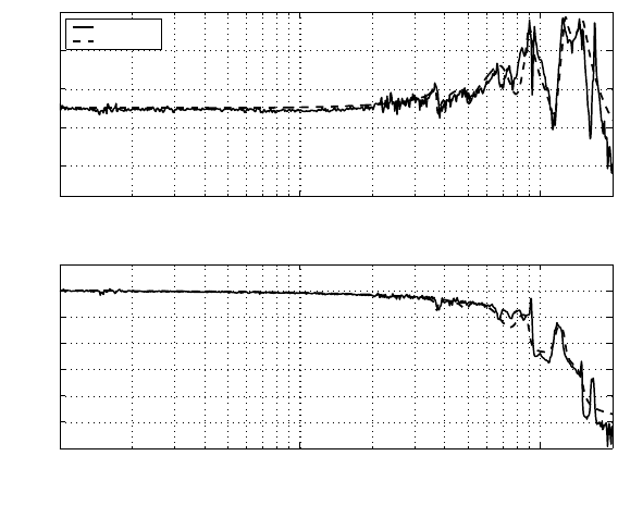
The frequency responses of the microactuator are shown in Figure 8.13. Six reso-
nance modes at 3.7, 4.9, 6.9, 9, 12.7 and 15 kHz are i ncluded in the model.
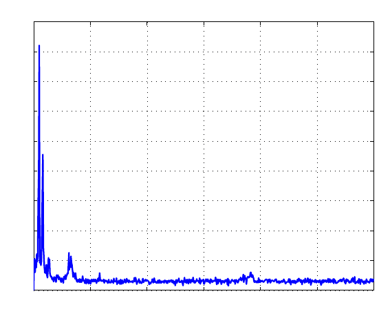
The disturbance dist ributio n is reflected in the non-repeatable runout power spec-
trum of the measured PES in Figure 8.14. It is noticed that there is a vi bration mode
at 650 Hz due to disk vibration. The objective here is to use the above KYP method
to d esign a linear dynamic output feedback controller C(z) for the microactuator in
Figur e 8.13 such that its closed-loop system is stable and the disturbance centering at
650 Hz is suppressed sufficiently. 45 kHz sampling rate is used in the servo control
design. The control algorithm is implemented with the digital position error signal
generated from DSP TMS320C6711. Currently, due to the limitation by th e DSP
speed, with this sampling rate the platform can support up to 10
th
order cont roller.
Because 65 0 Hz i s at a relative low frequency range, we just involve the static
part of the mi croactuator represented by a pade delay in the control design with the
KYP Lemma. After t hat, notch filters f or the resonance modes at 3.7, 9 and 1 5
kHz will be used to compensate the dynamic part, which will not change a lot th e
obtained performance o f the low frequency part. The 4.9 and 6.9 kHz resonance
modes, seen in Figure 8.13, have relatively small magnitud es and can be ignored as
long as t hey are not excited in the control loop. The resonance mode at 12.7 kHz is
not considered in the control design as it is not excited easily and does not affect the
whole loop stabili ty when the 15 kHz mode is compensated.
The pade delay model is given by
P
pade−delay
= −5.6234
s −2 · π · 17000
s + 2 · π · 17000
, (8.39 )
which is pre-compensated by the proportional-integral (PI) controller:
Int(z) = 0.027(−
z
z − 0.999
+ 0.5). (8.40 )
Due to the first order pade-delay model used in the computation of LMIs, the
computation of control ler can be very efficient.
The desired specifications for the sensit ivity function S(z) are set as:
Spec.(a) |S(f )| < 0 dB, f ≤ 500 Hz,
Spec.(b) |S(f )| < −10 dB, 610 Hz ≤ f ≤ 670 Hz,
Spec.(c) |S(f )| < 9.54 dB, f ≥ 19 kHz.
Spec. (b) means to attenuate the disturbances centering at 6 50 Hz by 10 dB at least.
The parameters of Q(z) in (8.19) with τ = 1 are attained by solving three LMIs of
the form (8.7) corresponding to Spec. (a), (b) and (c). The resultant C(z) is a 10
th
order cont roller.
For the sake of comparison, the phase-lead p eak filter (PLPF) of t he form in (8.28)
with values K = 0.4, φ = −0.584, ω
0
= 2π650, and ξ = 0.0632, is also applied to

178 Modeling and Control of Vibratio n in Mechanical Systems
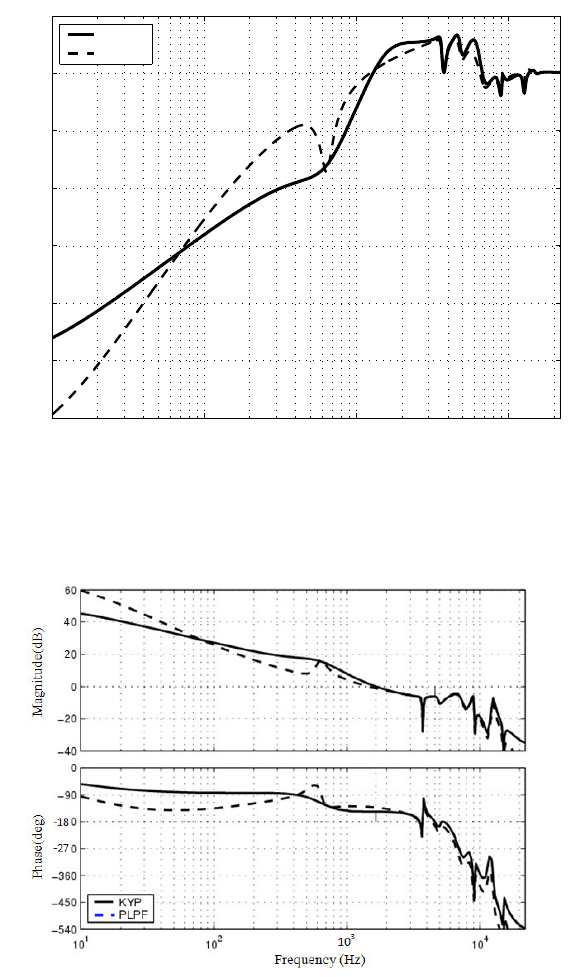
suppress the low frequency disturb ances around 650 Hz, and the sensitivity function
comparison is shown in Figure 8.15. It can be seen that the KYP method achieves
better disturbance rejection from 60 Hz to 1 kHz, although they have almost th e
same rejection capabilit y in the very narrow band arou nd 650 Hz. However, t he
KYP method gives a poorer disturbance rejectio n performance for frequency below
60 Hz than the PLPF method.
In the open loop comparison in Figure 8.16, the phase margin (PM) with the PLPF
method is much higher, while the bandwidth is lower and the gain margin (GM) is
comparable with the KYP Lemma method. Consistent with the sensitivity functions
in Figure 8.15, the PES NRRO power spectrum comparison is shown in Figure 8.17
which clearly shows that the KYP based design gives a better disturbance rejecti on
around 6 50 Hz than the PLPF alth ough at 650 Hz they offer a similar performance.
From Figure 2.20 , it is known that the spectrum of the t rue PES y is given by
S
y
= |P (z)S(z)|
2
×|d
1
|
2
+ |S(z)|
2
|d
2
|
2
+ |T (z)|
2
× |n|
2
(8.41 )
= S
e
− |S(z)|
2
×|n|
2
+ |T (z)|
2
×|n|
2
, (8.42)
where S
e
is in (8.1), and T (z) = 1 −S(z) is the closed loo p transfer fu nction. Thus
the 3σ value of the true PES can be assessed f rom the power spectrum S
e
in Fi gure
8.17 with the known level of noise n. As a result it is improved from 6.4 nm with
the PLPF method to 6 nm with the KYP Lemma method.
In the above application, only the first order Q(z) is used. A higher order Q(z)
offers more desig n freedom and has the potential of achieving better results. How-
ever, wh at ever Q(z) is used, the resultant sensitivity funct ion has to comply w ith the
Bode integral t heorem, meaning that it is not possible to achieve disturbance rejec-
tion across th e entire frequency range. To further improve the disturbance rejection
at low frequency for th e KYP Lemma-based design, we shall incorporate a nonlinear
compensation in Chapt er 13.
8.7 Conclusion
This chapter has applied the generalized KYP Lemma in the microactuator clo sed-
loop design to suppress the narrow band disturbances. The system design problem
with multiple specifications on the gain properties of the sensitivity f unction over
several frequency ranges has been sol ved by the LMI optimization based on the
KYP Lemma. The Youla parametrization approach has been used in the feedback
controller design. Practical applications have been demonstrated for narrowband
high frequency and mid-fr equency disturbance rejecti on. The resultant controller
verifies that the desir ed specifications to reject the disturbances have been satisfied
via the search for the coefficients o f Q(z) in the Youla parametrization approach.

Generalized KYP Lemma-Based Loop Shaping Control Design 179
10
2
10
3
10
4
0
10
20
30
40
Magnitude(dB)
10
2
10
3
10
4
−600
−500
−400
−300
−200
−100
0
100
Phase(deg)
Frequency(Hz)
Measured
Modeled
FIGURE 8.13
Frequency response of the PZT microactuator.

180 Modeling and Control of Vibratio n in Mechanical Systems
0 1000 2000 3000 4000 5000 6000
0
0.5
1
1.5
2
2.5
3
3.5
4
x 10
−3
Frequency(Hz)
NRRO magnitude(µm)
FIGURE 8.14
PES NRRO power spectrum calculated fro m measured PES signal without servo
control, reflecting the vibration distribution of the system (3σ = 21 nm including the
noise 3σ = 15.2 nm).

Generalized KYP Lemma-Based Loop Shaping Control Design 181
10
1
10
2
10
3
10
4
−60
−50
−40
−30
−20
−10
0
10
Magnitude(dB)
Frequency(Hz)
KYP
PLPF
FIGURE 8.15
Comparison of sensitivity functions.
FIGURE 8.16
Open loop frequency responses (PLPF (GM: 6 dB, PM: 50 deg., Bandwidth
1.4kHz)); KYP(GM: 6 dB, PM: 34 deg., Bandwidth : 1.7 kHz))).

182 Modeling and Control of Vibratio n in Mechanical Systems
0 1000 2000 3000 4000 5000 6000
0
0.2
0.4
0.6
0.8
1
x 10
−3
Frequency(Hz)
NRRO magnitude(µm)
KYP
PLPF
650Hz
FIGURE 8.17
NRRO power spectrum wi th PLPF and KYP (50% reduction befor e 1 kHz).

9
Combined H
2
and KYP Lemma-Based
Control Design
9.1 Introduction
As a closed-loop shaping method, the KYP Lemma-based approach allows d esigners
to impose perfor mance requirements over selected finite frequency ranges so as to
have the desired sensitivity function that is able to reject the disturbances in these
specific frequency ranges. Subsequently, the posi tioning accuracy can be impr oved
to some extent. However, the KYP Lemma-based loop shaping method does not
count for overall positioning error mi nimization w hich can be translated into the
H
2
optimal con trol problem by taking into consideration the distur bance and noise
models. On the other hand, the H
2
control design whi ch incorporates all disturbance
and noise models can result in an average performance across the entire frequency
range and a high order controller. Thus it usually does not have the flexibility to
specifically reject di sturbances at certain frequency ranges, which however may be
dominant factors that influence the overall performance. Therefore there is a need to
suppress disturbances of specific frequencies when minimizing the positioning erro r.
This motivates us to incorporate the KYP Lemma-based method with the H
2
control
method in this chapter. With the selected specific disturbances handled by the KYP
Lemma-based design, th e H
2
control is formulated with a lower order disturbance
model, excluding the disturbances covered in the above design. This will not only
release the computation burden in the H
2
control design but also result in a lower
order cont roller.
In this chapter, we will apply the combined control design method to a PZT mi-
croactuator such t hat a disturbance at 650 Hz is rejected with the KYP Lemma-based
design and at the same t ime overall positioning error is minimized via the H
2
control
design. Then one more disturbance at 2 kHz near the servo bandwidth 1kHz is al so
considered as a specific disturbance to be rejected via the the KYP Lemma-based
design. The design procedure will be illustrated and the resultant controller will be
verified via an experiment. A seri es of simulation and experimental results will show
the effectiveness of the control design method in terms of enhancing positioning ac-
curacy.
183
