Chilingarian G.V. et al. Surface Operations in Petroleum Production, II
Подождите немного. Документ загружается.

115
from it the pressure head due to the vertical column of treating fluid from the
surface to the fracture depth. The value
of
Ap,
does not include the influence of a
propping agent present in the treatment fluid (Halliburton, 1976).
The "leak-off" volume
is
part of the fluid in contact with the formation fracture
faces which penetrates into the formation pores. This lost fluid does not help extend
the fracture. The results of a typical fluid-loss test conducted in
a
laboratory are
presented in Fig.
4-15.
The fluid-loss volume versus time curve exhibits two parts:
(1)
generation of a filter cake on the surface of the fracture; and (2) "leak-off''
through the filter cake. Fluid loss
is
controlled in the field by the addition of
fluid-loss additives to the fracturing fluid. These additives decrease the permeability
of the filter cake on the fracture face and, thus, slow down the rate of fluid loss. The
fracture dimensions decrease with increasing leak-off rates.
Fracture
inclination
Allen and Roberts (1982) pointed out that knowledge of the direction or
inclination of a fracture is desirable in order to:
(1)
estimate the increase in
post-fracturing productivity,
(2)
determine whether multiple fracturing is feasible or
Fracture
BOnomho'e propagation pressure
Fracture
closure pressure
Horizontal Vertical matrix
Reservoir
@
Sand
Y
=
0.30.
E
=
3
x
lo6
-
@
Shale
Y
=
0.33, E
=
4
Y
lo6
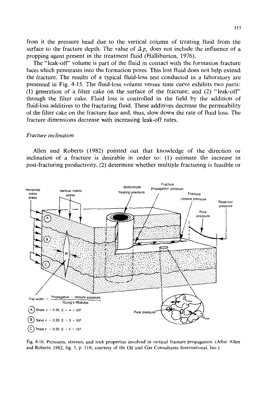
Fig.
4-16.
Pressures, stresses, and rock properties involved in vertical fracture propagation. (After Allen
and
Roberts, 1982, fig.
5,
p.
119; courtesy of the Oil and Gas Consultants International, Inc.)
116
not, and
(3)
avoid extension of fractures into areas where they are not desired.
Figure 4-16 illustrates the pressures, stresses, and other rock properties involved in
vertical fracture propagation about a wellbore. The inclination of horizontal or
vertical fractures in sedimentary rocks can affect “leak-off” during fracture oper-
ations. The productivity ratio of the fractured well after fracturing
is
also affected
because the fracture angle controls the zones which are opened to the wellbore.
Usually, the fracture plane tends to be vertical when the fracture gradient is
<
0.7
psi/ft. Horizontal fractures occur when the fracture gradient is
>
1.0
psi/ft.
Pressure in the fracture must exceed the pore pressure by an amount equal to the
minimum effective rock matrix stress in order to hold the fracture open after
initiation. This pressure is often called “closure” pressure.
Vertical fractures tend to extend further into the formation than horizontal
fractures. It is important to mention here that the writers in their experience have
not
observed horizontal fractures. The length and width
of
a fracture depends upon
the existence and location of barriers above and below the fractured zone. Inasmuch
as horizontal stresses are higher in shales than in the producing sandstone zone, the
length of a fracture increases, whereas its height does not. Barriers less than 10
ft
in
thickness are usually not restrictive, whereas barriers
>
25
ft
are restrictive. In
carbonate reservoirs, anhydrites, like shales, can form impermeable barriers.
Fracture
initiation
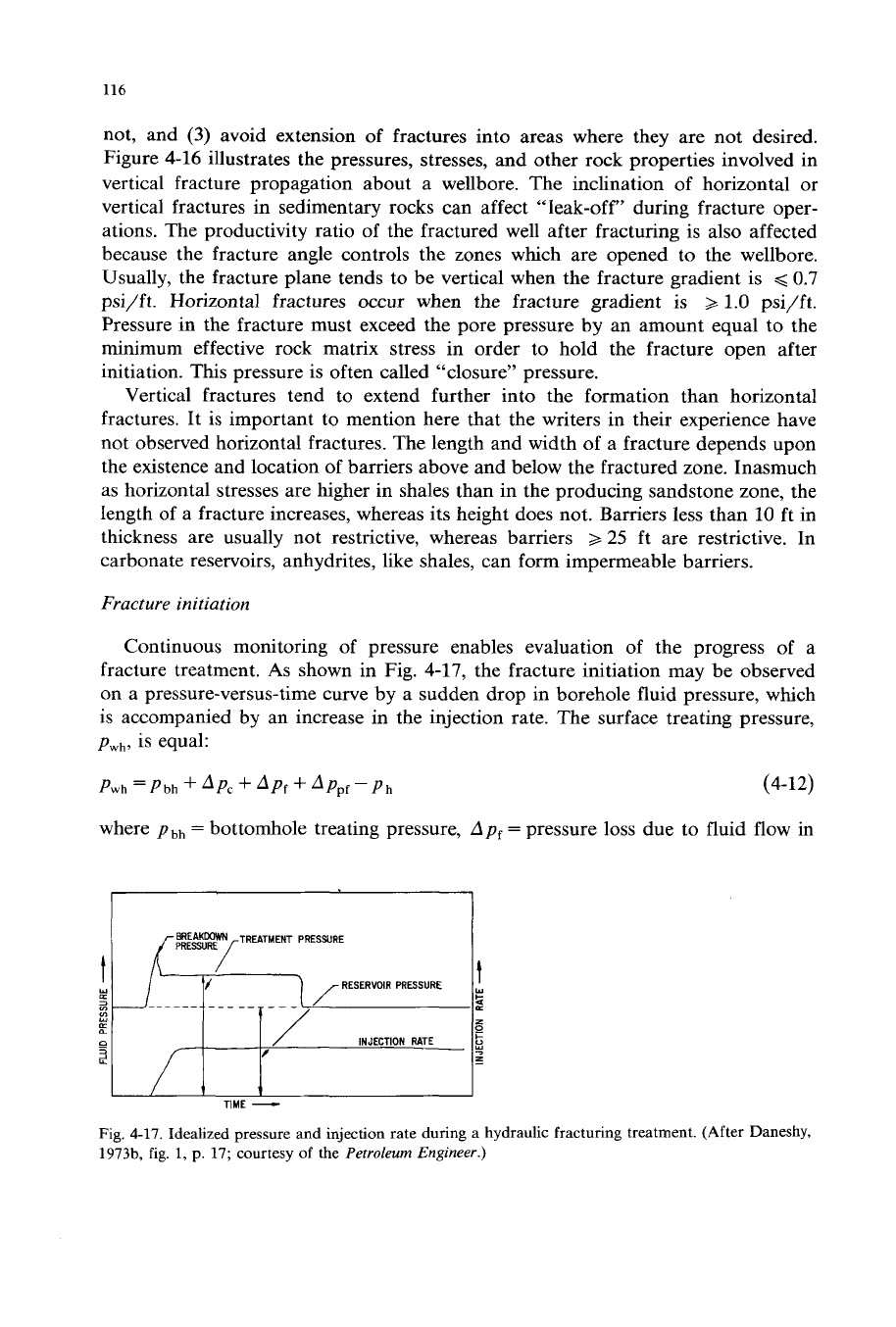
Continuous monitoring of pressure enables evaluation of the progress of a
fracture treatment.
As
shown in Fig. 4-17, the fracture initiation may be observed
on a pressure-versus-time curve by a sudden drop in borehole fluid pressure, which
is accompanied by an increase in the injection rate. The surface treating pressure,
pwh,
is equal:
Pwh
=Pbh
+
‘pc
+
‘pf
-k
‘Ppf-ph
(4-12)
where
pbh
=
bottomhole treating pressure,
Ap,
=
pressure loss due to fluid flow in
INJECTION
RATE
z
-
TIME
-
Fig.
4-17. Idealized pressure and injection rate during a hydraulic fracturing treatment. (After Daneshy,
3973b,
fig.
1,
p.
17;
courtesy
of
the
Petroleum Engineer.)
117
Fig. 4-18. Schematic showing location
of
pressure losses in a fracturing treatment. (Courtesy of the
Halliburton
Co.,
1976, fig. 9.1, p. 42.)
the wellbore between the wellhead and perforations,
Appf
=
pressure loss through
the perforations,
ph
=
hydrostatic pressure due to the weight of the column
of
fluid
between the injection pump and perforations, and
Ap,
=
pressure losses due to fluid
flow in the fracture between the wellbore and tip
of
the fracture (see Fig.
4-18).
FLOW
RATE THROUGH PERFORATION
-
BPM
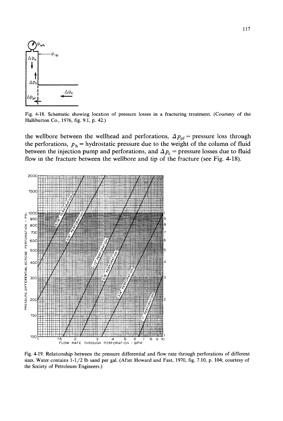
Fig. 4-19. Relationship between the pressure differential and flow rate through perforations
of
different
sizes.
Water contains 1-1/2
Ib
sand per gal. (After Howard and Fast, 1970, fig. 7.10, p. 104; courtesy
of
the Society of Petroleum Engineers.)
118
SAND-POUNDS
PER
GALLON
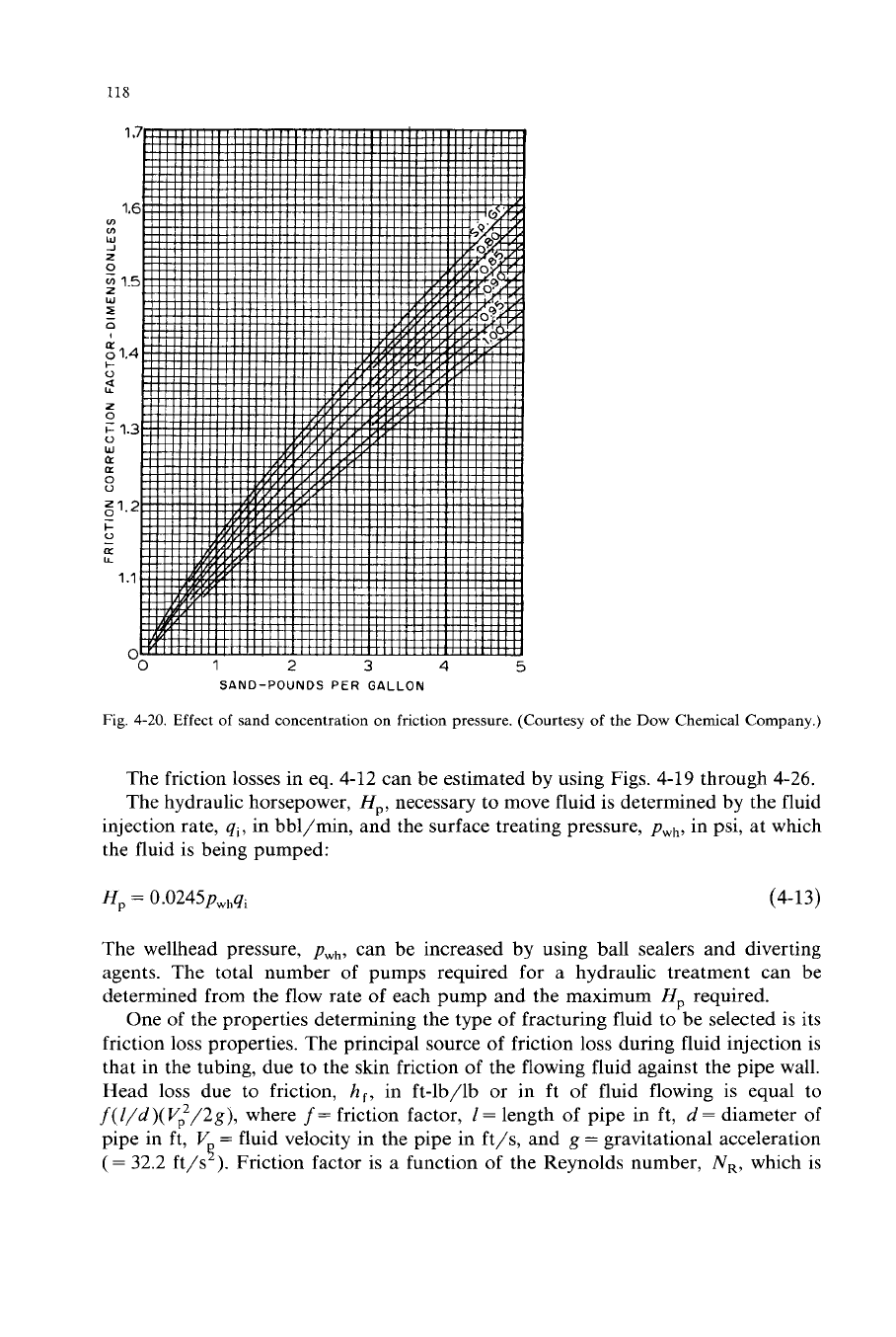
Fig. 4-20.
Effect of sand concentration on friction pressure. (Courtesy
of
the
Dow
Chemical Company.)
The friction losses in eq.
4-12
can be estimated
by
using Figs.
4-19
through
4-26.
The hydraulic horsepower,
Hp,
necessary to move fluid is determined
by
the fluid
injection rate,
qi,
in bbl/min, and the surface treating pressure,
pwh,
in psi, at which
the fluid is being pumped:
Hp
=
0.0245pw,,qi
(4-13)
The wellhead pressure,
pwh,
can be increased
by
using ball sealers and diverting
agents. The total number of pumps required for a hydraulic treatment can be
determined from the flow rate
of
each pump and the maximum
Hp
required.
One of the properties determining the type of fracturing fluid to be selected is its
friction loss properties. The principal source of friction
loss
during fluid injection is
that in the tubing, due to the skin friction of the flowing fluid against the pipe wall.
Head loss due to friction,
h,,
in ft-lb/lb or in ft of fluid flowing is equal to
f(//d)(
V,2/2g),
where
f=
friction factor,
/
=
length of pipe in ft,
d
=
diameter of
pipe in ft,
V
=
fluid velocity in the pipe in ft/s, and
g
=
gravitational acceleration
(=
32.2
ft/s
).
Friction factor is a function of the Reynolds number,
N,,
which is
4
119
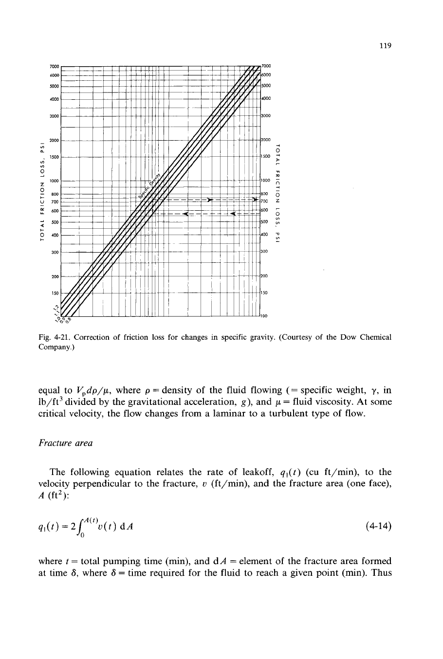
Fig.
4-21.
Correction of friction
loss
for changes in specific gravity. (Courtesy
of
the
Dow
Chemical
Company.)
equal to
V,dp/p,
where
p
=
density of the fluid flowing
(=
specific weight,
y,
in
lb/ft3 divided by the gravitational acceleration,
g),
and
p
=
fluid viscosity. At some
critical velocity, the flow changes from a laminar to a turbulent type of flow.
Fracture area
The following equation relates the rate of leakoff,
ql(t)
(cu ft/min), to the
velocity perpendicular to the fracture,
u
(ft/min), and the fracture area (one face),
A
(ft2):
ql(t)
=
2Jbl(')u(t)
dA
(4-14)
where
t
=
total pumping time (min), and dA
=
element of the fracture area formed
at time
6,
where
6
=
time required for the fluid to reach a given point (min). Thus
120
FLOW RATE
-
BPM
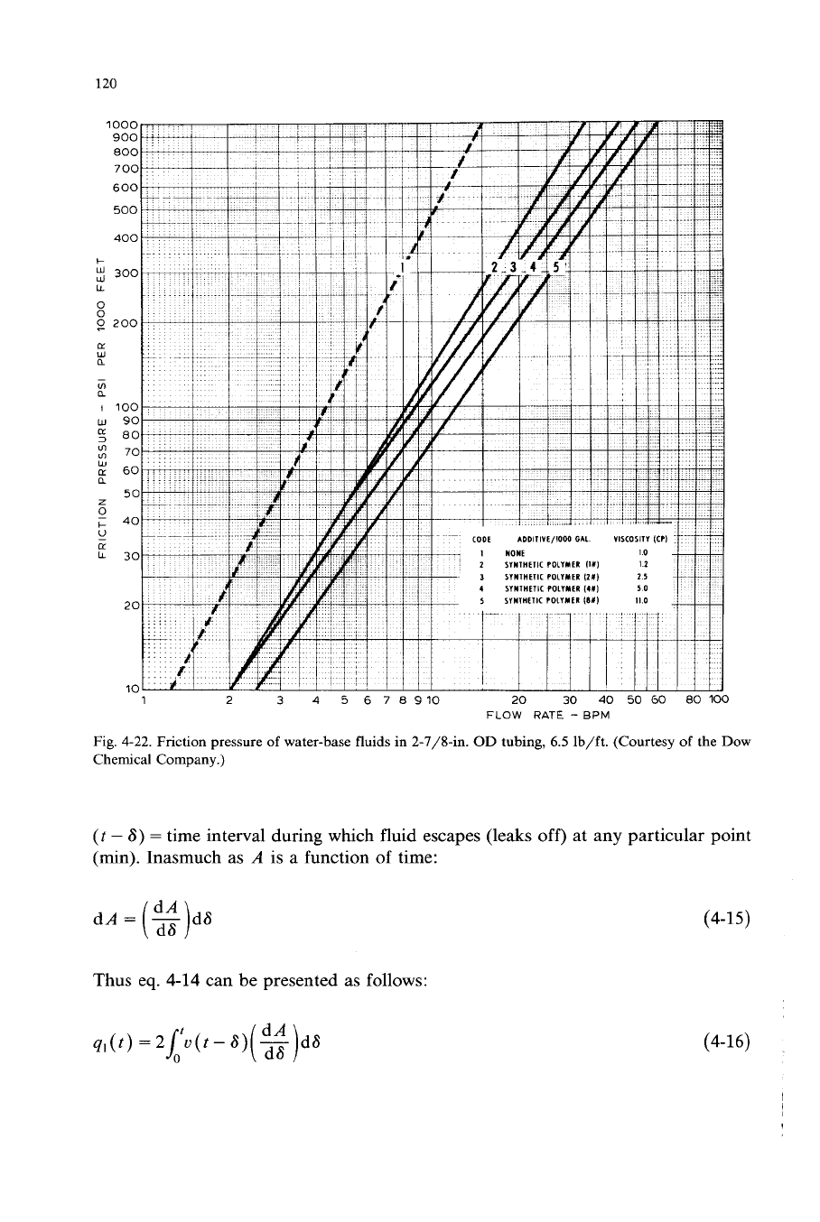
Fig.
4-22.
Friction pressure
of
water-base
fluids
in 2-7/8411.
OD
tubing,
6.5
lb/ft. (Courtesy
of
the Dow
Chemical Company.)
(t
-
8)
=
time interval during which fluid escapes (leaks
off)
at any particular point
(min).
Inasmuch as
A
is a function of time:
dA=
-
d8
(Y
j
Thus eq. 4-14 can be presented as follows:
q1(t)=2i'u(t-8)
(3
-
d8
(4-15)
(4-16)
121
1000
900
800
700
CODE ADDITIVE/1000 GAL VISCOSITY ICPI
I
NONE
I
600
500
I
MODlflED GUM GUM
IIOI)
7-
3
MODIFIED GUM GUM
12011
16
I
MODIFIED
GUM
GUM
llOX)
65
-
I
MODIFIED
GUM
GUM
(6011
130
400
6
MODIFIED GUM GUM
l8OX)
ZIC
1
2
3
4
5
6
78910
20
30
40
50
60
80
100
FLOW
RATE
-
BPM
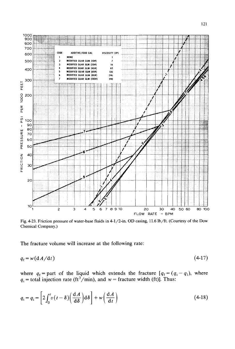
Fig.
4-23.
Friction pressure
of
water-base fluids in
4-1/2411.
OD
casing,
11.6
lb/ft. (Courtesy
of
the Dow
Chemical Company.)
The fracture volume will increase at the following rate:
qt
=
w(dA/dt) (4-17)
where
qf
=
part
of
the liquid which extends the fracture
[
qf
=
(4t
-
4,),
where
qt
=
total injection rate (ft3/min), and
w
=
fracture width
(ft)].
Thus:
(4-18)

122
Fig.
4-24. Friction pressure
of
water-base fluids in 7-in. OD casing, 23 lb/ft. (Courtesy of the Dow
Chemical Company.)
Carter
(1957)
solved the latter equation for
A
at any time,
A([),
by means
of
Laplace transformation, assuming that
qi
is constant and the equation for
u(t)
is
known:
(4-19)
where x
=
2Ca/w,
C
=
fracturing-fluid coefficient
in
ft/& and erfc(x)
=
the
complementary error function of (x), the values of which have been calculated and
123
3
4
5
6
7
8910
Polymer (Friction Reducer)
(2.5)
3.0
Guar (Friction Reducer)
(10)
8.5
-
Guar (Friction Reducer)
(40)
65.0
Acid Retarded with a Natural Gum
5.0
1
1
3
4
5
6
78VlO
10
30
40
60
80
FLOW
RATE
-
BPM
1000
9W
8W
700
6W
500
ux)
3w
ZW
IW
?O
10
0
10
I0
10
10
0
0
,
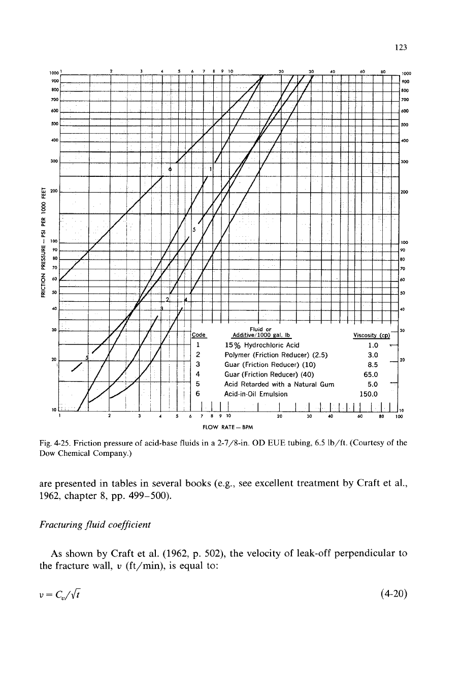
Fig.
4-25.
Friction pressure
of
acid-base fluids in
a
2-7/8411.
OD
EUE
tubing,
6.5
lb/ft. (Courtesy
of
the
Dow
Chemical Company.)
are presented in tables in several books (e.g., see excellent treatment by Craft et al.,
1962, chapter
8,
pp. 499-500).
Fracturing
fluid
coefficient
As
shown by Craft et al.
(1962,
p.
502),
the velocity
of
leak-off perpendicular to
the fracture wall,
v
(ft/min),
is
equal to:
v
=
C"/fi
(4-20)
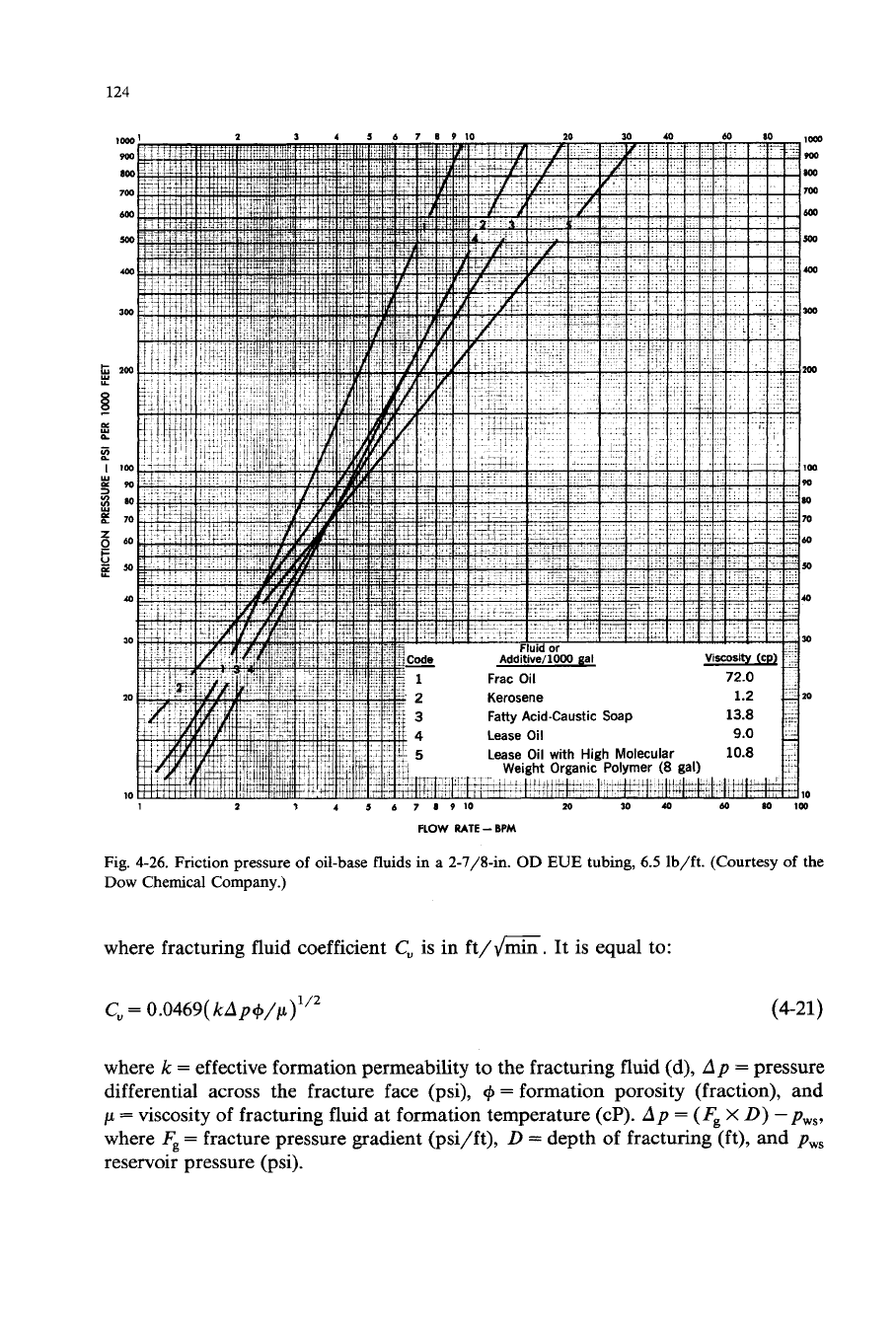
124
Fig.
4-26.
Friction
pressure of oil-base
fluids
in
a 2-7/8411.
OD EUE
tubing,
6.5 lb/ft. (Courtesy
of
the
Dow
Chemical
Company.)
where fracturing fluid coefficient
C,
is in ft/G. It is equal to:
C,
=
0.0469(
kAp+/p)’”
(4-21)
where
k
=
effective formation permeability to the fracturing fluid (d),
Ap
=
pressure
differential across the fracture face (psi),
+
=
formation porosity (fraction), and
p
=
viscosity of fracturing fluid
at
formation temperature (cP).
Ap
=
(
Fg
X
0)
-
pw,,
where
Fg
=
fracture pressure gradient (psi/ft),
D
=
depth of fracturing (ft), and
p,,
reservoir pressure (psi).