Chilingarian G.V. et al. Surface Operations in Petroleum Production, II
Подождите немного. Документ загружается.

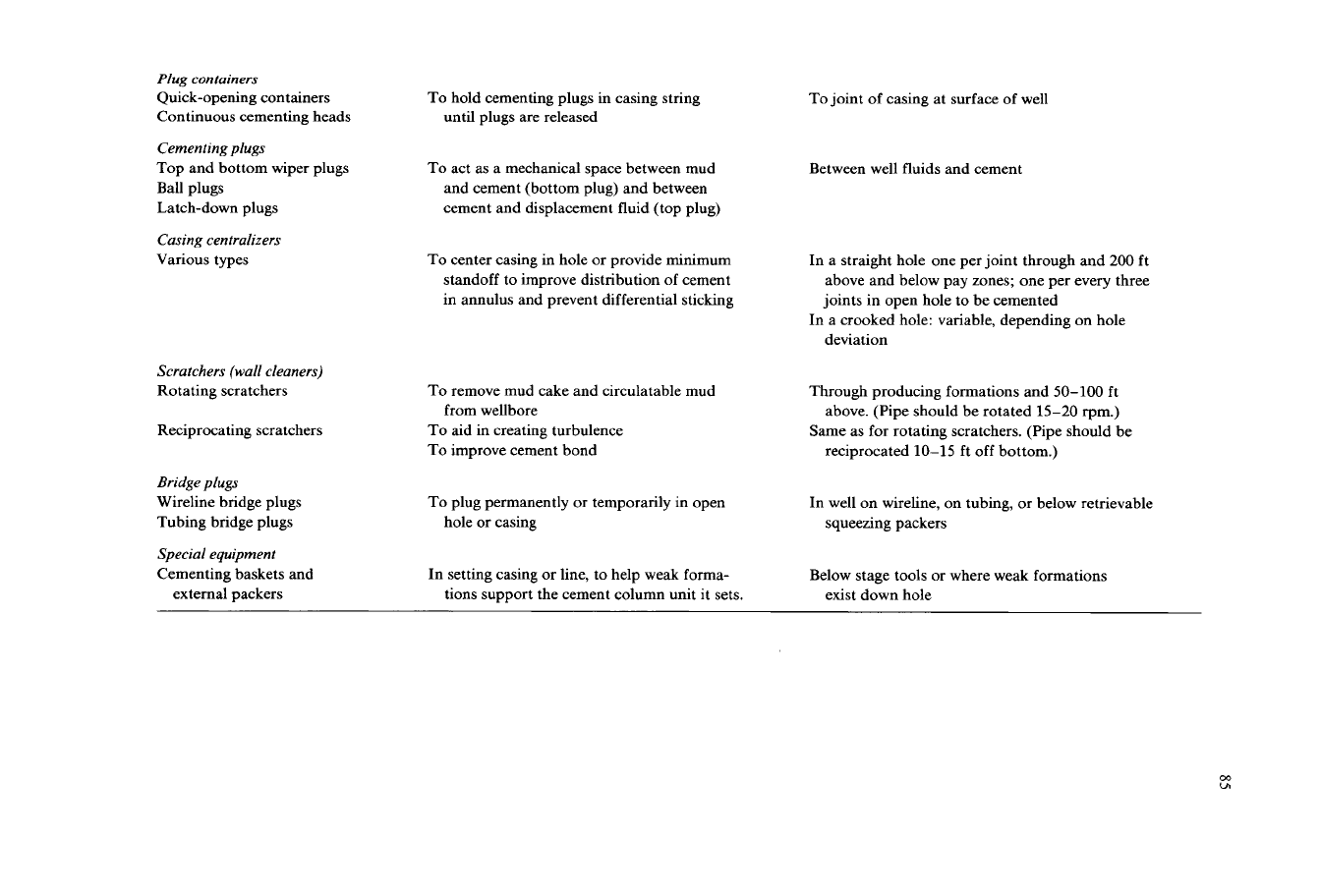
Plug
containers
Quick-opening containers
Continuous cementing heads
Cementing plugs
Top and bottom wiper plugs
Ball plugs
Latch-down plugs
Casing centralizers
Various types
Scratchers (wall cleaners)
Rotating scratchers
Reciprocating scratchers
Bridge plugs
Wireline bridge plugs
Tubing bridge plugs
Special equipment
Cementing baskets and
external packers
To hold cementing plugs in casing string
until plugs are released
To act as a mechanical space between mud
and cement (bottom plug) and between
cement and displacement fluid (top plug)
To
center casing in hole or provide minimum
standoff to improve distribution of cement
in annulus and prevent differential sticking
To
remove mud cake and circulatable mud
To
aid in creating turbulence
To
improve cement bond
from wellbore
To plug permanently or temporarily in open
hole or casing
In setting casing or line, to help weak forma-
tions support the cement column unit it sets.
To joint
of
casing at surface of well
Between well fluids and cement
In a straight hole one per joint through and
200
ft
above and below pay zones; one per every three
joints in open hole to be cemented
deviation
In a crooked hole: variable, depending on hole
Through producing formations and 50-100 ft
above. (Pipe should be rotated 15-20 rpm.)
Same as for rotating scratchers. (Pipe should be
reciprocated 10-15 ft off bottom.)
In well on wireline, on tubing, or below retrievable
squeezing packers
Below stage tools or where weak formations
exist down hole
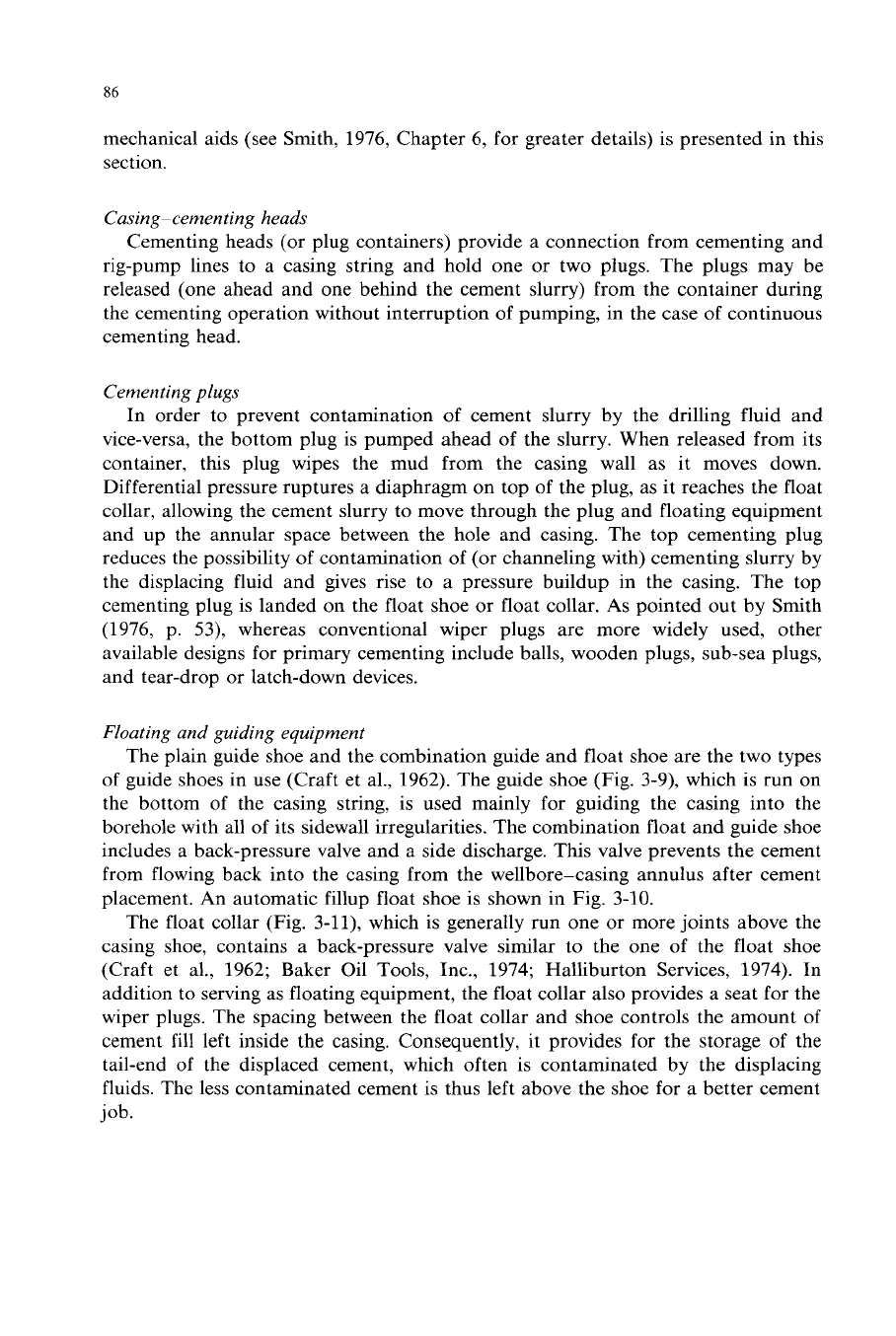
86
mechanical aids (see Smith, 1976, Chapter 6, for greater details) is presented in this
section.
Casing- cemen ting heads
Cementing heads (or plug containers) provide a connection from cementing and
rig-pump lines to a casing string and hold one or two plugs. The plugs may be
released (one ahead and one behind the cement slurry) from the container during
the cementing operation without interruption of pumping, in the case of continuous
cementing head.
Cementing plugs
In order to prevent contamination
of
cement slurry by the drilling fluid and
vice-versa, the bottom plug is pumped ahead of the slurry. When released from its
container, this plug wipes the mud from the casing wall as it moves down.
Differential pressure ruptures a diaphragm on top of the plug, as it reaches the float
collar, allowing the cement slurry to move through the plug and floating equipment
and up the annular space between the hole and casing. The top cementing plug
reduces the possibility
of
contamination of (or channeling with) cementing slurry by
the displacing fluid and gives rise to a pressure buildup in the casing. The top
cementing plug is landed on the float shoe or float collar.
As
pointed out by Smith
(1976, p. 53), whereas conventional wiper plugs are more widely used,
other
available designs for primary cementing include balls, wooden plugs, sub-sea plugs,
and tear-drop
or
latch-down devices.
Floating and guiding equipment
The plain guide shoe and the combination guide and float shoe are the two types
of guide shoes in use (Craft et al., 1962). The guide shoe (Fig. 3-9), which
is
run on
the bottom of the casing string, is used mainly for guiding the casing into the
borehole with all of its sidewall irregularities. The combination float and guide shoe
includes a back-pressure valve and a side discharge. This valve prevents the cement
from flowing back into the casing from the wellbore-casing annulus after cement
placement. An automatic fillup float shoe is shown in Fig. 3-10.
The float collar (Fig. 3-11), which is generally run one or more joints above the
casing shoe, contains a back-pressure valve similar to the one of the float shoe
(Craft et al., 1962; Baker Oil Tools, Inc., 1974; Halliburton Services, 1974). In
addition to serving as floating equipment, the float collar also provides a seat for the
wiper plugs. The spacing between the float collar and shoe controls the amount of
cement fill left inside the casing. Consequently, it provides for the storage of the
tail-end of the displaced cement, which often is contaminated by the displacing
fluids. The less contaminated cement is thus left above the shoe for a better cement
job.
87
Fig.
3-10.
Automatic fillup float
shoe:
(a) valve open for running in hole; and (b) valve closed
to
prevent
back-flow
of
cement once placed. (Courtesy
of
the Halliburton Services.)
Fig.
3-11.
Float collars: (a)
Flow
control collar; (b) concrete baffle collar; and (c) Type
“E”
float collar.
(Courtesy
of
the Halliburton Services.)
88
FIGURE
1
FIGURE
2
FIGURE
3
FIGURE
4
DISPLACING
CEMENT
FOR
FIRST STAGE
DROPPING
OPENING
PLUG
DISPLACING
CEMENT FOR
SECOND STAGE
MULTIPLE
STAGE
CEMENTER
CLOSED
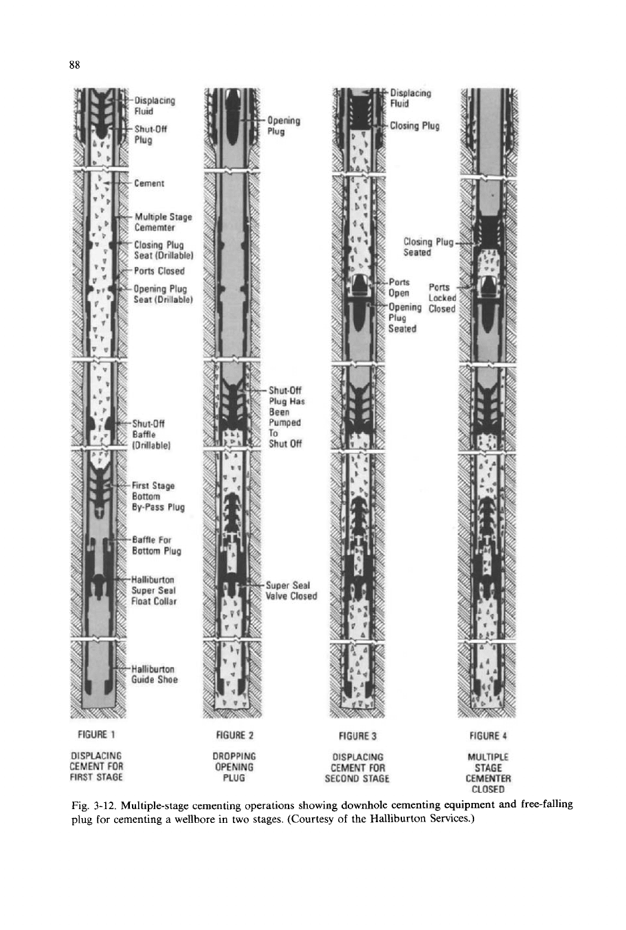
Fig.
3-12.
Multiple-stage cementing operations showing downhole cementing equipment and free-falling
plug
for
cementing a wellbore in two stages. (Courtesy
of
the Halliburton Services.)
89
Stage-cementing tools
Multiple-stage cementing tools must be used in cases when it is desirable to
cement two or three sections behnd the casing. Smith (1976) pointed out that stage
cementing (Fig.
3-12)
usually reduces drilling fluid contamination and decreases the
possibility of formation breakdown, that often causes lost circulation (Halliburton
Services, 1974).
Smith (1976, p. 51) pointed out that as the casing is run into the borehole, stage
I
,-Cement
-,
Mud
Coring
I
(1
b
Fig.
3-13.
Schematic diagram: (a) an improperly centered casing in the wellbore along with mud cake that
has not been removed from the walls
of
the wellbore; and (b) a properly centered casing in the wellbore
where the mud cake has been removed with scratchers and held securely by centralizers.
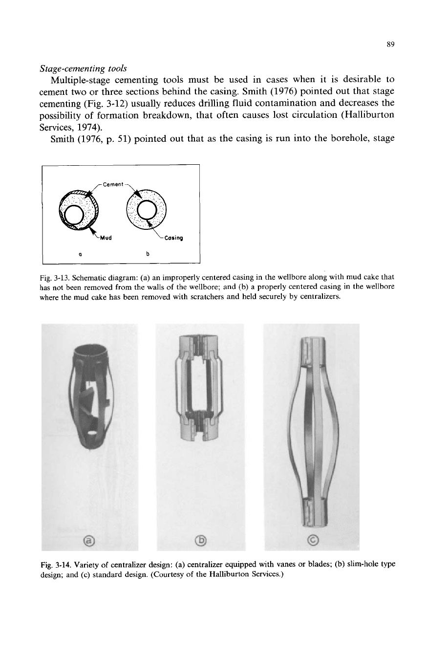
Fig. 3-14. Variety
of
centralizer design: (a) centralizer equipped with vanes or blades;
(b)
slim-hole type
design; and (c) standard design. (Courtesy
of
the Halliburton Services.)
90
tools are installed at a specific point in the casing string. Upon placing the cement
around the bottom of the casing, which constitutes the first stage, the tool can be
opened hydraulically either
(1)
with a plug pumped down the casing
or
(2)
with a
free-falling opening plug dropped down the casing. Cement can be circulated
through the outside ports when the tool
is
opened. A closing plug closes a sleeve
over the side port upon placement of all the cement slurry. Primary advantage of
this method (see Halliburton,
1974)
lies in the fact that the shutoff plug used in the
first stage prevents overdisplacement of the first-stage cement. In cases where the
cement must be placed in the annular space from the bottom of the casing up to or
above the stage tool, the displacement stage-cementing method can be used. In deep
or deviated holes, in whch too much time is needed for a free-falling plug to reach
the tool, ths method is often used.
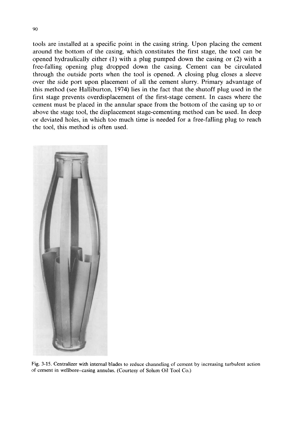
Fig.
3-15.
Centralizer with internal blades to reduce channeling
of
cement
by
increasing turbulent action
of
cement in wellbore-casing annulus. (Courtesy
of
Solum Oil
Tool
Co.)
91
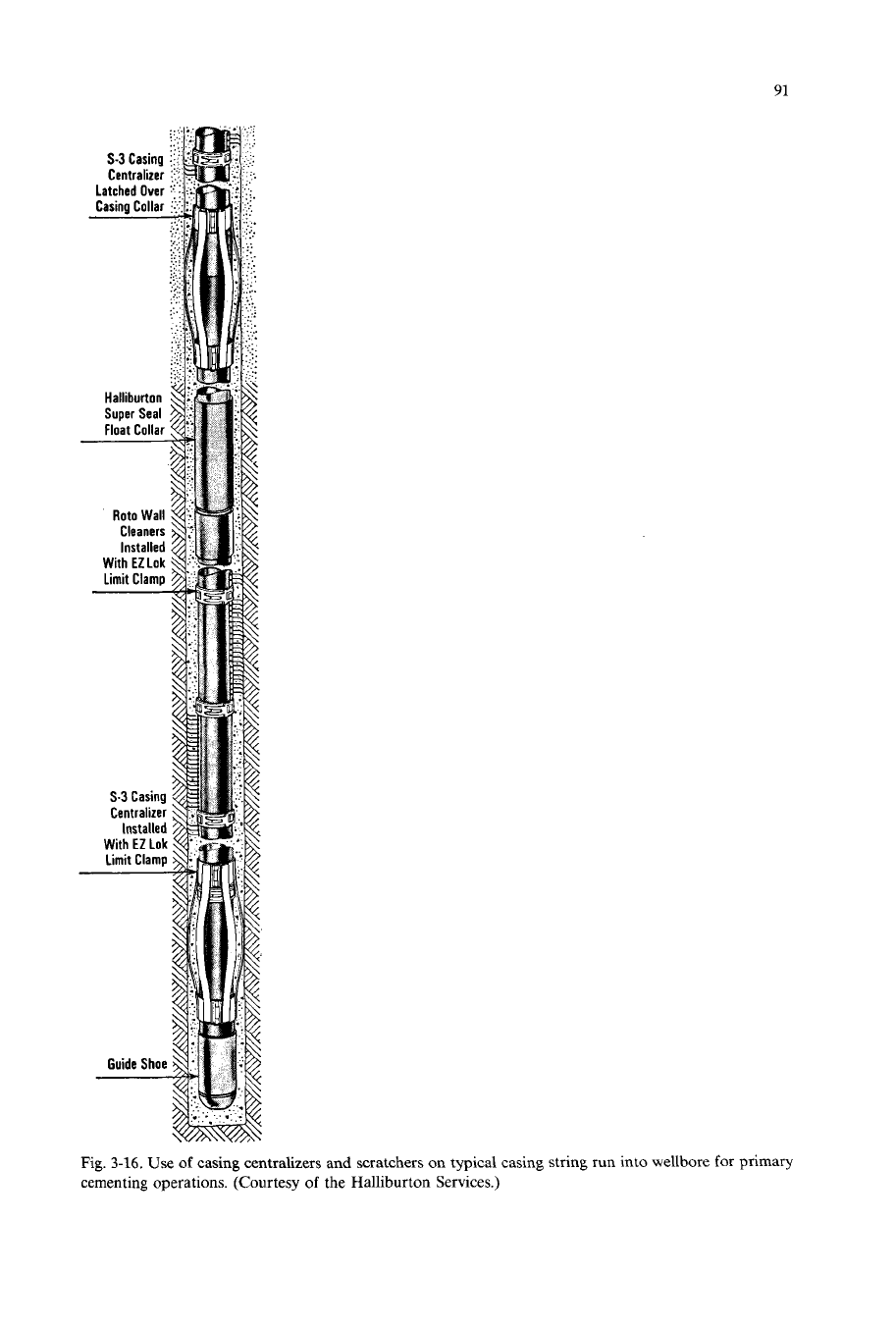
Fig.
3-16. Use
of
casing centralizers and scratchers on typical casing string run into wellbore
for
primary
cementing operations. (Courtesy
of
the Halliburton Services.)
92
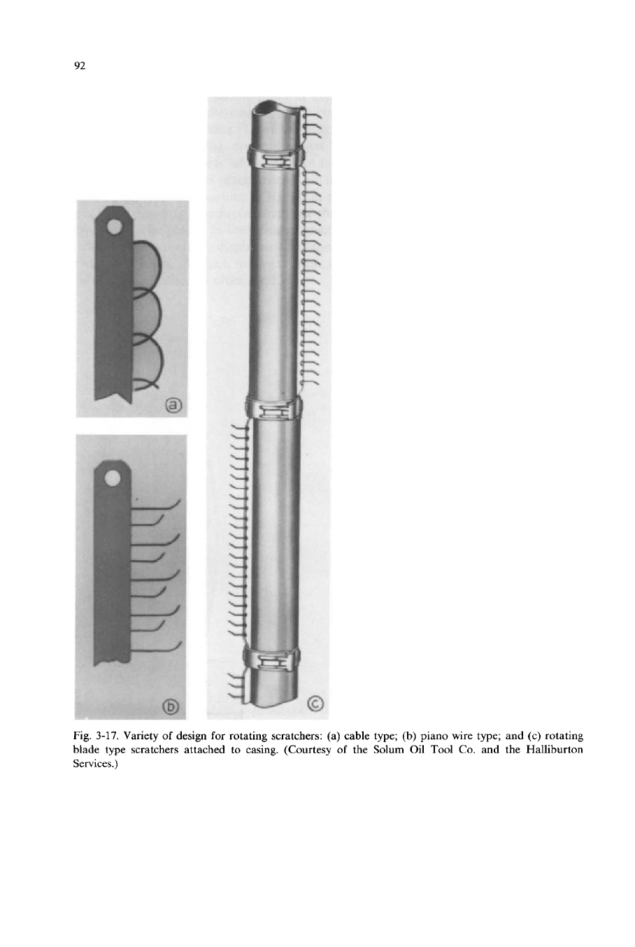
Fig. 3-17. Variety
of
design
for
rotating scratchers: (a) cable type; (b) piano wire type; and (c) rotating
blade type scratchers attached to casing. (Courtesy
of
the
Solum
Oil Tool
Co.
and the Halliburton
Services.)
93
Casing centralizers
The effectiveness of the seal between wellbore and casing is determined in a large
measure by the uniformity of the cement sheath around the pipe (Fig. 3-13).
Generally, the pipe is in contact with the wall of the borehole at several places,
because most holes are not straight. In order to keep the casing away from the walls
of the borehole, centralizers are used (Figs. 3-14, 3-15 and 3-16). Although there is
an agreement among investigators as to the need to centralize the casing to obtain a
better cement job (Goins, 1971), there is some disagreement as to how frequently
centralizers should be placed. The design of centralizers varies widely with vendors
and for different hole applications. The API specifications (API, 1960b; API
Standards 10B) insure minimum strength requirements based upon
(1)
restoring
force and
(2)
starting force (Table 3-V).
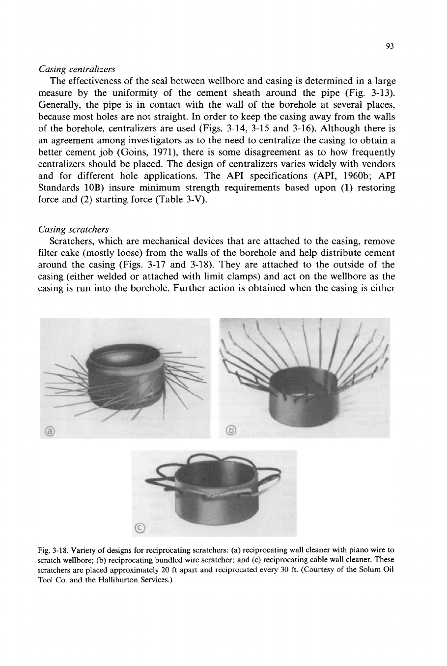
Casing scratchers
Scratchers, whch are mechanical devices that are attached to the casing, remove
filter cake (mostly loose) from the walls of the borehole and help distribute cement
around the casing (Figs. 3-17 and 3-18). They are attached to the outside of the
casing (either welded or attached with limit clamps) and act on the wellbore as the
casing is run into the borehole. Further action is obtained when the casing is either
Fig.
3-18.
Variety of designs for reciprocating scratchers: (a) reciprocating wall cleaner with piano wire to
scratch wellbore; (b) reciprocating bundled wire scratcher; and (c) reciprocating cable wall cleaner. These
scratchers are placed approximately
20
ft apart and reciprocated every
30
ft. (Courtesy of the Solum Oil
Tool
Co. and the Halliburton Services.)
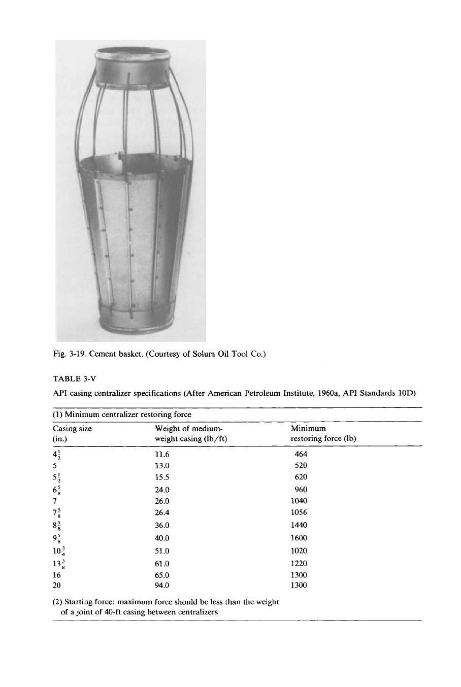
Fig.
3-19.
Cement basket. (Courtesy
of
Solum
Oil
Tool
Co.)
TABLE
3-V
API casing centralizer specifications (After American Petroleum Institute,
1960a,
API Standards
10D)
(1)
Minimum centralizer restoring force
Casing size
Weight of medium- Minimum
(in.)
weight casing (lb/ft) restoring force (lb)
4; 11.6 464
5
13.0 520
5;
15.5 620
6; 24.0 960
7
26.0 1040
7;
26.4 1056
9; 40.0 1600
8;
36.0
1440
10
:
51.0 1020
13; 61
.O
1220
16 65.0 1300
20 94.0
1300
(2)
Starting force: maximum force should be
less
than the weight
of
a joint of 40-ft casing between centralizers