Canale L.C.F., Mesquita R.A., Totten G.E. Failure Analysis of Heat Treated Steel Components
Подождите немного. Документ загружается.

requirement of 46 to 48 HRC for 4330V-
modified steel heat treated to the 1515 to
1655 MPa (220 to 240 ksi) tensile strength
range. The hardness of the nut was 45 HRC,
which was above the hardness requirement of
40 to 43 HRC. The high hardness value did
not appear to be detrimental.
A hydrogen analysis conducted on the hinge
bolt yielded a value of 1.5 ppm, which is con-
sidered low to cause hydrogen embrittlement.
The diameter of the bolt at the fracture was
measured to be 10.6 mm (0.419 in.), meeting
the drawing requirement of 10.7+0.25 mm
(0.422+0.010 in.). The radius at the transition
where the failure occurred was 1.5 mm
(0.060 in.), meeting the drawing requirement of
1.6+0.25 mm (0.063+0.010 in.).
A spectrographic analysis verified that the
bolt was 4330V-modified steel.
A tensile test was conducted on a production
bolt. The bolt failed in the threaded area. The
failing load was determined to be 17,600 kg
(38,820 lb). No requirement was available.
A metallographic section was removed
through the origin location shown in Fig. 29.
The specimen was prepared using standard
metallographic techniques. Figure 31 shows
micrographs taken of the fracture origin. The
tempered martensitic microstructure was nor-
mal. No untempered martensite was present.
Corrosion products were observed on the frac-
ture surface at the origin (Fig. 32). However,
there was no evidence of pitting or other corro-
sion processes that would have produced the
corrosion products. No aluminum IVD was
present on the surface at the origin, because the
IVD had been removed prior to measuring
residual stresses.
Based on the results of this investigation, it is
concluded that the inboard flap hinge bolt failed
in a delayed mode of failure, which was most
likely stress-corrosion cracking. No material
anomalies were observed that would account for
the failure of the inboard flap hinge bolt.
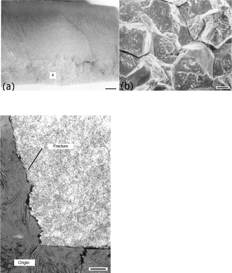
Fig. 26 Typical fracture features. (a) Overall view (500 mm). (b) Intergranular fracture apparent at fracture origin (7 mm)
Fig. 27
Metallographic examination of primary crack. Frac-
ture path followed prior-austenite grain boundaries.
No precipitates in grain boundaries (50 mm) were observed.
366 / Failure Analysis of Heat Treated Steel Components
Name ///sr-nova/Dclabs_wip/Failure_Analysis/5113_351-393.pdf/Chap_11/ 18/8/2008 3:46PM Plate # 0 pg 366
Failure Analysis of a Nose Landing
Gear Piston Axle
This investigation determined the mode and
initiating cause of failure of a nose landing gear
(NLG) piston axle. Failure of the piston axle
occurred on the aircraft during taxiing after the
aircraft had accumulated approximately 60 h in
service. When failure occurred, the nose wheel
completely separated from the piston strut. The
NLG piston assembly was fabricated from 300M
steel and heat treated to a 1930 to 2070 MPa (280
to 300 ksi) ultimate strength range. The axle
was then shot peened and low-embrittlement
cadmium plated. White paint was applied to the
inside and outside surfaces of the axle, with
exception of the two land surfaces for the wheel
bearing cans. The failed NLG piston assembly
was removed from the wheel and submitted for
examination. Figure 33 shows the as-received
piston assembly and the failed axle.
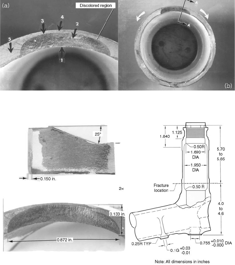
A visual examination of the failed axle
revealed that the fracture surface followed
a circumferential path and contained a large
discolored region (Fig. 34). Except for the
discolored region, the fracture was typically
gray colored and contained chevron markings,
as shown in Fig. 35, indicating the failure orig-
inated at the discolored region. It was deter-
mined that the discolored region, from which the
failure appeared to originate, was located at the
bottom of the axle, at approximately the 6:30
o’clock position. The sketch in Fig. 36 shows the
approximate failure location. Failure of the axle
initiated approximately 145 to 149 mm (5.70 to
5.85 in.) from the threaded outboard end.
An optical examination with a stereomicro-
scope at up to 30· magnification confirmed that
the failure of the axle originated at the discolored
region. Chevron marks were evident that indi-
cated the crack propagated away from the ends
of the discolored region, terminating at an area
diametrically across from it, as shown in
Fig. 35(b). The discolored region extended
along the circumference of the axle for a cord
distance of 22.15 mm (0.872 in.) and a maxi-
mum depth from the inside diameter surface
of 3.38 mm (0.133 in.). Actual wall thickness
at that location was 3.81 mm (0.150 in.). The
plane of the discolored region was approxi-
mately 25
from being perpendicular to the
longitudinal axis of the axle, along machining
marks. These dimensions were shown in Fig. 33
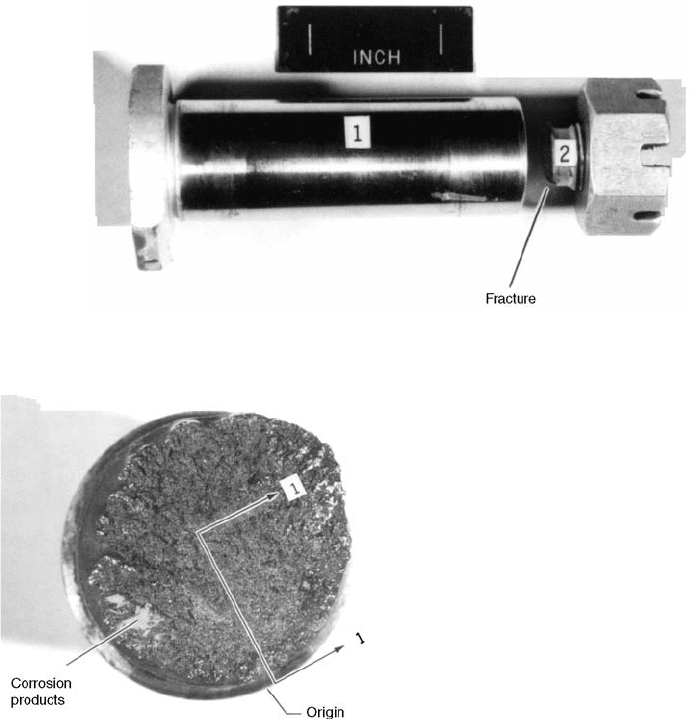
Fig. 28 As-received flap hinge bolt and nut
Fig. 29 Fracture surface of the failed flap hinge bolt
Case Studies of Steel Component Failures in Aerospace Applications / 367
Name ///sr-nova/Dclabs_wip/Failure_Analysis/5113_351-393.pdf/Chap_11/ 18/8/2008 3:46PM Plate # 0 pg 367
and 36. When examined, the discolored region
showed a color variance ranging from a gold
color to reddish brown. Also, small patches of
blue were evident. This observed color variation
is a characteristic typically observed on steel
surfaces that have been exposed to elevated
temperature, such as during heat treatment
(Ref 1). The machining marks indicate a surface
much rougher than is normal.
The hardness measurements were made at
several locations around the circumference of
the axle adjacent to the fracture surface. The
hardness measured 53 to 55 HRC, which con-
formed to the drawing requirement of 53 to 55
HRC for 300M steel heat treated to a 1930 to
2070 MPa (280 to 300 ksi) condition.
A section containing the discolored region
was removed from the axle and examined with
the SEM. The locations where SEM examin-
ations were performed are shown in Fig. 35(a).
Prior to SEM examination, the discolored region
was cleaned with acetone and replication in an
attempt to remove the scale from the fracture
surface. After several attempts, only a small
amount of the scale could be eliminated, indi-
cating the scale was firmly attached to the frac-
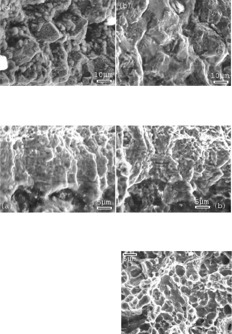
ture surface. The SEM fractographs adjacent to
the inside diameter surface (area 1) were pri-
marily intergranular and appeared to be covered
with scale. At areas beyond the inside diameter
surface, the SEM fractographs revealed a mixed
intergranular with transgranular features and
patches of scale. These are shown in Fig. 37.
Along the periphery of the discolored region,
fatigue striations could be observed at a higher
magnification, as shown in Fig. 38. The depth of
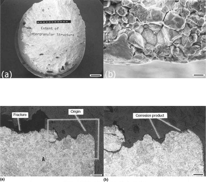
Fig. 30
SEM examination of the flap hinge bolt. (a) Overall view of fracture surface (1.25 mm). (b) Intergranular fracture evident at
origin (10 mm)
Fig. 31
Micrographs of the fracture origin. (a) Section 1-1, Fig. 29. Fracture is intergranular at prior-austenite grain boundaries
(50 mm). (b) Location A showing evidence of corrosion product at fracture facets (25 mm)
368 / Failure Analysis of Heat Treated Steel Components
Name ///sr-nova/Dclabs_wip/Failure_Analysis/5113_351-393.pdf/Chap_11/ 18/8/2008 3:46PM Plate # 0 pg 368
the fatigue growth region was approximately
0.05 mm (0.002 in.). Rapid fracture extended
beyond the fatigue region. The SEM fractograph
in Fig. 39 shows dimpled features that char-
acterize a ductile mode of rapid fracture. When
examining the discolored region with SEM at
low magnification, there was no evidence of
shear lip along the inner diameter surface, which
indicates that the fracture did not initiate sub-
surface, as would be the case for delayed failure
resulting from hydrogen embrittlement.
In an attempt to determine the composition
of the observed scale or to identify any con-
taminant that may be associated with the fracture
surface, an energy-dispersive x-ray (EDX) ana-
lysis was performed on the discolored region.
The EDX analysis revealed no other element
except the ones common to the base metal
composition.
Fig. 32
Micrograph showing the microstructure at the frac-
ture origin. Microstructure consists of quenched and
tempered martensite (25 mm). IVD, ion vapor deposited
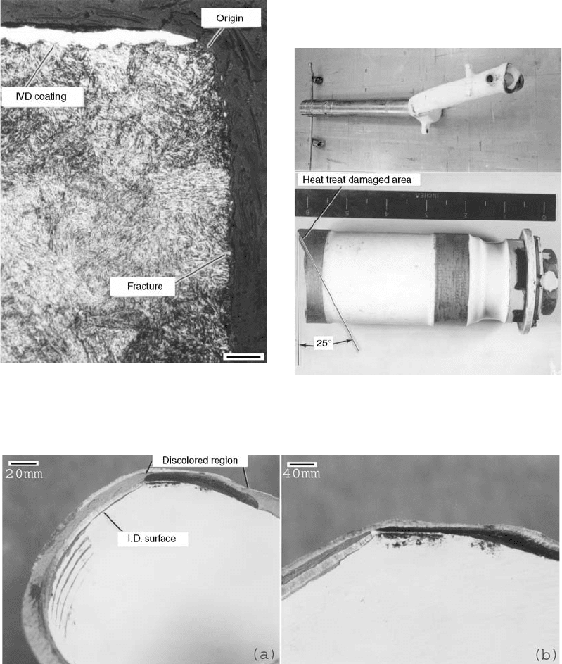
Fig. 33
As-received nose landing gear piston assembly and
the failed axle
Fig. 34 Discolored region of the fracture
Case Studies of Steel Component Failures in Aerospace Applications / 369
Name ///sr-nova/Dclabs_wip/Failure_Analysis/5113_351-393.pdf/Chap_11/ 18/8/2008 3:46PM Plate # 0 pg 369
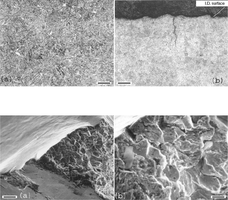
To examine the microstructure of the dis-
colored region, a section was removed (section
A-A, Fig. 35b) for metallographic examination.
The microstructure was tempered martensite,
which is typical for 300M steel heat treated to
the 1655 to 2070 MPa (280 to 300 ksi) ultimate
strength range (Fig. 40). A secondary crack was
observed starting at the inner diameter surface
(Fig. 40b), at a location showing large surface
irregularities. In an attempt to investigate this
secondary crack, the crack was opened and the
fracture surface examined with a light micro-
scope and the SEM. The fracture depth was
relatively small (0.25 mm, or 0.01 in.), which
made it difficult to determine with the light
microscope if a high-temperature scale was
present. The SEM examination revealed inter-
granular and ductile transgranular features
(Fig. 41). These features suggest a secondary
heat treat crack.
Fig. 35
Fracture surface of the failed axle. (a) Black arrows show locations for SEM examination. (b) White arrows show fracture
direction and location of metallographic sections.
Fig. 36 Axle wall thickness, discolored region dimensions, and fracture location
370 / Failure Analysis of Heat Treated Steel Components
Name ///sr-nova/Dclabs_wip/Failure_Analysis/5113_351-393.pdf/Chap_11/ 18/8/2008 3:47PM Plate # 0 pg 370
In order to verify the material composition,
one section of the piston axle was chemically
analyzed, using the atomic absorption spectro-
scopy method. The results of the analysis are
shown in Table 1. These values met the require-
ments of AMS 6419 for 300M steel.
In summation, the results of this investigation
indicated that the failure of the NLG piston axle
was introduced from a pre-existing defect. This
defect was present on the axle prior to the final
assembly of the part to the aircraft. The defect
had a brittle intergranular fracture surface
feature and a discoloration characteristic of a
thermal or quench crack. These phenomena
demonstrated that the crack occurred on the
piston axle during or prior to the heat treatment
Fig. 37
SEM fractographs showing brittle intergranular structure in discolored region of the fracture surface. (a) Intergranular fracture
partially covered with scale at the area adjacent to the inner diameter surface (10 mm). (b) Fracture surface away from the
inner diameter surface showing intergranular and transgranular features (10 mm)
Fig. 38
SEM fractographs showing fatigue growth at regions close to the outer diameter surface. (a) At boundary of discolored region
(5 mm). (b) Outside the boundary of the discolored region (5 mm)
Fig. 39
Rapid fracture at location outside the discolored
region (5 mm)
Case Studies of Steel Component Failures in Aerospace Applications / 371
Name ///sr-nova/Dclabs_wip/Failure_Analysis/5113_351-393.pdf/Chap_11/ 18/8/2008 3:47PM Plate # 0 pg 371
process. Because of the machining marks and
the initiation of cracking at these asperities, it
is possible that cracking occurred during the
machining operation, in a fashion similar to the
formation of grinding cracks.
Based on the results of this examination, it is
concluded that the failure of the NLG piston
axle was due to the pre-existing crack on the
axle. This crack was created prior to or during
heat treatment of the part.
Multiple-Leg Aircraft-Handling Sling
A new multiple-leg aircraft-handling sling
that had just received proof testing was found to
have a cracked clevis. The failed adapter was
machined from 4330V-modified steel that had
been heat treated to a 1240 to 1380 MPa (180 to
200 ksi) tensile strength range.
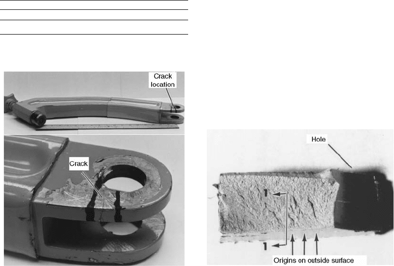
Figure 42 shows the adapter part of the mul-
tiple-leg aircraft-handling sling as received for
examination. Also shown in Fig. 42 is the loca-
tion and appearance of the crack that was at a
clevis. The crack penetrated completely through
the wall of the clevis.
The fracture surface was opened, and the
fracture surface was examined visually and at up
to 50 · magnification using a stereomicroscope.
Figure 43 shows a macrograph of the fracture
surface. Fracture ridges indicated that origins
were present on the outside surface of the clevis.
The fracture surface appeared faceted, which is
characteristic of an intergranular, delayed mode
of failure.
Fig. 40
Microstructure and secondary cracking at the discolored region. (a) Normal tempered martensite typical of 300M (25 mm).
(b) Secondary cracking apparent on inner diameter surface (100 mm)
Fig. 41
SEM fractographs of opened secondary crack. (a) Origin of secondary crack (33 mm). (b) Intergranular fracture apparent
(10 mm)
372 / Failure Analysis of Heat Treated Steel Components
Name ///sr-nova/Dclabs_wip/Failure_Analysis/5113_351-393.pdf/Chap_11/ 18/8/2008 3:47PM Plate # 0 pg 372
An SEM was used to examine the fracture
surface and the side of the clevis at the origin.
Figure 44 shows SEM photographs document-
ing topographic features of the fracture surface
and corrosion pitting on the side of the clevis
at the fracture origin. The pits were coated with
primer, which indicated they were present
prior to painting. Also documented in Fig. 44
are intergranular topography and corrosion pro-
ducts at the fracture origins. These features are
all characteristic of a stress-corrosion failure
(Ref 4).
A laboratory overload fracture produced in
the clevis was examined in the SEM. Figure 45
shows an SEM fractograph documenting dim-
ples that are characteristic of an overload mode
of failure.
Hardness measurements were made on the
adapter to verify the heat treat condition. The
hardness of the adapter was 41.4 HRC, and this
met the hardness requirement of 40 to 43 HRC.
The hydrogen content of the adapter was
determined to be 1 ppm, which is considered
low in relation to producing a hydrogen em-
brittlement failure.
A metallographic specimen was prepared
through a fracture origin. The specimen was
prepared using standard metallographic techni-
ques. Figure 46 shows the microstructure, which
was normal (tempered martensite).
Also shown in Fig. 46 is a corrosion pit that
was coated with paint, indicating the pit was
present prior to painting.
Based on the results of this investigation,
it was concluded that the adapter failed due to
stress-corrosion cracking. Corrosion pits at the
fracture origin were present prior to painting.
Failure Analysis of an Aircraft Hoist
Sling during Static Test
An aircraft hoist sling was successfully tested
to an ultimate load of 136,000 kg (300,000 lb).
However, shortly after relieving the load,
the weld on the aft right-hand fitting failed.
The fitting was fabricated from welded 17-4PH
stainless steel plates.
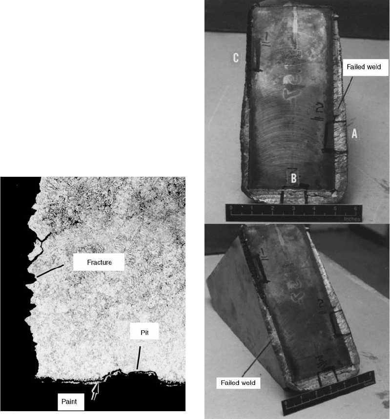
Figure 47 shows the as-received failed portion
of the test fixture. The failure occurred in a
consumable electrode weld that traversed
around the length of the fracture, which was
approximately 69 cm (27 in.). A dark, dis-
colored area was present in the fractured weld
over a length of approximately 122 mm (4.8 in.)
(location C).
Lack of fusion was a general condition
of the weld. Figure 48 shows a typical area
where lack of fusion was present in the weld.
Table 1 Chemical analysis of nose landing
gear piston axle
Chemical composition, %
Si Mn Ni Cr Mo V Fe
1.42 0.72 1.79 0.68 0.49 0.008 bal
Fig. 42
As-received failed multiple-leg aircraft-handling
sling
Fig. 43
Appearance of the fracture surface of the multiple-
leg aircraft-handling sling
Case Studies of Steel Component Failures in Aerospace Applications / 373
Name ///sr-nova/Dclabs_wip/Failure_Analysis/5113_351-393.pdf/Chap_11/ 18/8/2008 3:47PM Plate # 0 pg 373

Figure 49 documents the direction of fracture,
as evidenced by the convergence of river pat-
terns, at a typical location. The side of the
fracture containing location C had been placed
in tension due to bending. Portions of the frac-
ture at locations A, B, and C shown in Fig. 47
were excised and examined on an SEM. Fig-
ure 50 shows SEM fractographs documenting
topographic features of these portions of the
fracture surface. The areas at A and B showed
evidence of overload, that is, dimples. At loca-
tion C in the dark, discolored area, the fracture
topography was different than at A and B. The
topography at location C was indicative of a
heated, oxidized surface.
An energy-dispersive spectrographic (EDS)
analysis conducted on the fractures at A and B
basically detected iron, chromium, nickel, and
copper. Nickel was not detected at location C.
The EDS spectra are shown in Fig. 51. The base
metal also showed the presence of iron, chro-
mium, nickel, and copper, which are present in
17-4PH stainless steel.
In conclusion, a different consumable weld-
ing electrode was used at location C (no nickel
present) than at locations A and B, where nickel
was present. It is recommended that 17-4PH
filler metal be used when welding 17-4PH steel.
Fig. 44
SEM fractographs of the service fracture. (a) Overall view. (b) Intergranular topography at origin. Original magnification:
1500·. (c) Pits on side of clevis at origin. Original magnification: 400·. (d) Pit and corrosion products at origin. Original
magnification: 1000·
Fig. 45
Dimpled rupture indicating overload failure in a
laboratory-produced failure. Original magnification:
5000·
374 / Failure Analysis of Heat Treated Steel Components
Name ///sr-nova/Dclabs_wip/Failure_Analysis/5113_351-393.pdf/Chap_11/ 18/8/2008 3:47PM Plate # 0 pg 374
This was apparently done at locations A and B
but not at C, where no nickel was present. Nickel
gives ductility to the weld and helps to prevent
cracking during cooling from the welding tem-
perature (Ref 7). It appears that at location C,
where no nickel was present, a crack was
formed, and the fracture surfaces at C became
discolored and pebbled in appearance at an
elevated temperature. Lack of fusion due to in-
sufficient heating was a general condition in the
weld, and this also contributed to the failure. In
summary, the weld, when placed under tension,
failed due to a crack and lack of fusion.
Failure Analysis of an Internal Spur Gear
This investigation analyzed cracks that were
present in an internal spur output gear. The
internal gear is part of the planetary gear system
for a canopy. The gear was made from 4340 steel
heat treated to the 1790 to 1930 MPa (260 to
280 ksi) tensile strength range. The part was
rejected after magnetic particle inspection due to
multiple crack indications along the inside sur-
faces next to the gear spline. The typical manu-
facturing sequence is forge, machine, heat treat,
grind, and plate.
Figure 52 shows the internal gear as received
for examination. Also shown in Fig. 52 is the
appearance of typical cracks, which were loca-
ted on the inside of the internal gear on areas
next to the gear spline. The cracks were located
completely around the circumference on both
sides of the gear. A crack was opened, and the
fracture surface was examined visually and at up
to 30 · magnification using a stereomicroscope.
Figure 53 shows macrographs of the fracture
surface. The fracture surface was discolored
Fig. 46
Microstructure consisting of tempered martensite at
fracture origin. Original magnification: 200· . Cor-
rosion pit coated with paint is evident in the micrograph.
Fig. 47
As-received portion of the failed aft right-hand fitting
for the hoist sling
Case Studies of Steel Component Failures in Aerospace Applications / 375
Name ///sr-nova/Dclabs_wip/Failure_Analysis/5113_351-393.pdf/Chap_11/ 18/8/2008 3:47PM Plate # 0 pg 375