Canale L.C.F., Mesquita R.A., Totten G.E. Failure Analysis of Heat Treated Steel Components
Подождите немного. Документ загружается.

from the mono-ball end. The bar was sup-
posedly swaged at 650
C (1200
F) and
then stress relieved.
The bar was then finish machined and heat
treated to a tensile strength range of 1930 to
2070 MPa (280 to 300 ksi). The part was
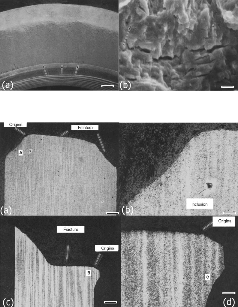
Fig. 7
SEM fractographs documenting typical topographic features of the T-head. (a) Typical portion of fracture surface, showing
typical origins at arrows (500 mm). (b) Typical fatigue striations on fracture surface of T-head (1 mm)
Fig. 8
Micrographs documenting the microstructure of the failed strain bar. (a) Section 1-1 from Fig. 4 showing a banded structure
(670 mm). (b) Location A, retainer ring groove (300 mm). (c) Section 2-2 from Fig. 4 showing banded structure (670 mm).
(d) Location B at origin showing banded structure (300 mm)
356 / Failure Analysis of Heat Treated Steel Components
Name ///sr-nova/Dclabs_wip/Failure_Analysis/5113_351-393.pdf/Chap_11/ 18/8/2008 3:45PM Plate # 0 pg 356
then magnetic particle inspected. Electro-
deposited nickel was specified for plating on
the inside diameter surface.
This plating is relatively soft, ductile, and
has a relatively high melting point. However,
electroless nickel, which has high phosphorus
content, was substituted without authorization.
This plating is hard and brittle and starts to melt
at the eutectic temperature of 880
C (1616
F).
Figures 16 and 17 show the MLG linear actu-
ating piston rod cylinder components as re-
ceived for examination. Two circumferential
fractures were located approximately 165 and
215 mm (6
1
/
2
and 8
1
/
2
in.) from the mono-ball
end of the piston rod cylinder. These two frac-
tures were joined by a longitudinal crack
approximately 50 mm (2 in.) long.
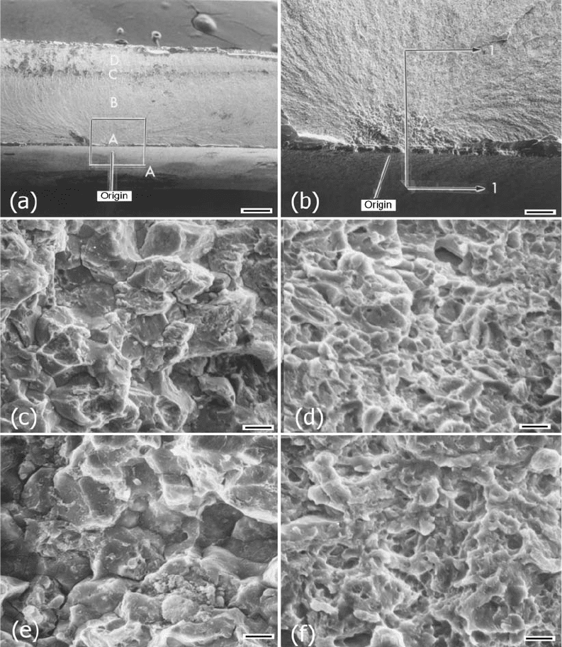
The longitudinal fracture was opened, and the
fracture surfaces were examined visually and at
up to 50 · magnification using a stereomicro-
scope. Figure 18 shows macrographs of the
fracture surfaces. The circumferential fractures
originated and terminated on the longitudinal
crack. The longitudinal crack exhibited a single,
intergranular-appearing origin on the inside
diameter surface of the piston rod cylinder. The
origin was located at approximately midlength
of the longitudinal crack, 200 mm (8 in.) from
the mono-ball end. An arrest mark was present
on the fracture surface at approximately 85% of
the wall thickness.
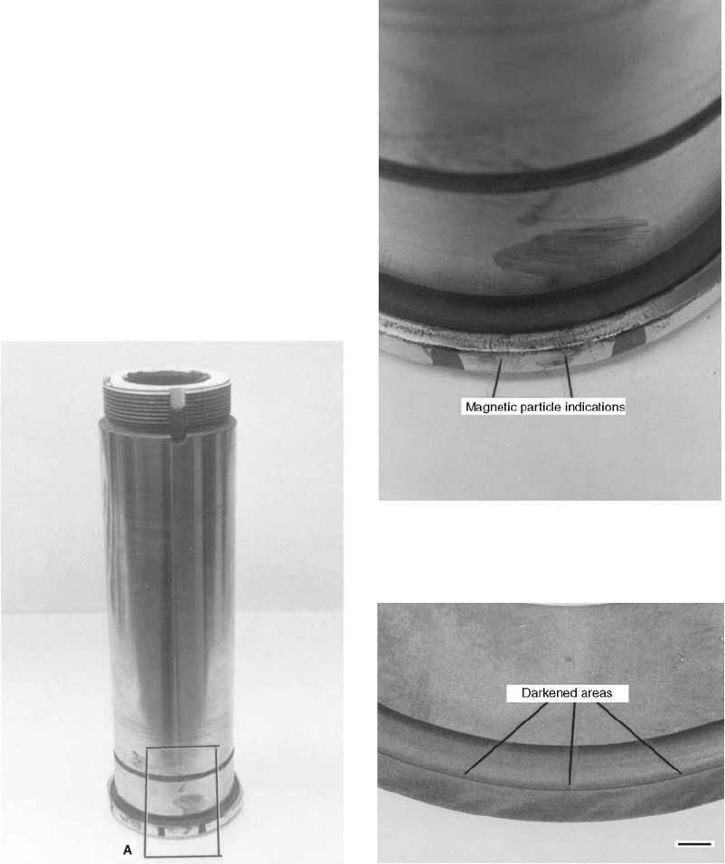
Fig. 9
Macrograph documenting the appearance of the
as-received main landing gear lever attach pin
Fig. 10
Magnetic particle inspection indications on the
flange of the main landing gear lever attach pin
Fig. 11
Overtempered (darkened areas) in the flang e
revealed by temper etching (2.5 mm)
Case Studies of Steel Component Failures in Aerospace Applications / 357
Name ///sr-nova/Dclabs_wip/Failure_Analysis/5113_351-393.pdf/Chap_11/ 18/8/2008 3:45PM Plate # 0 pg 357
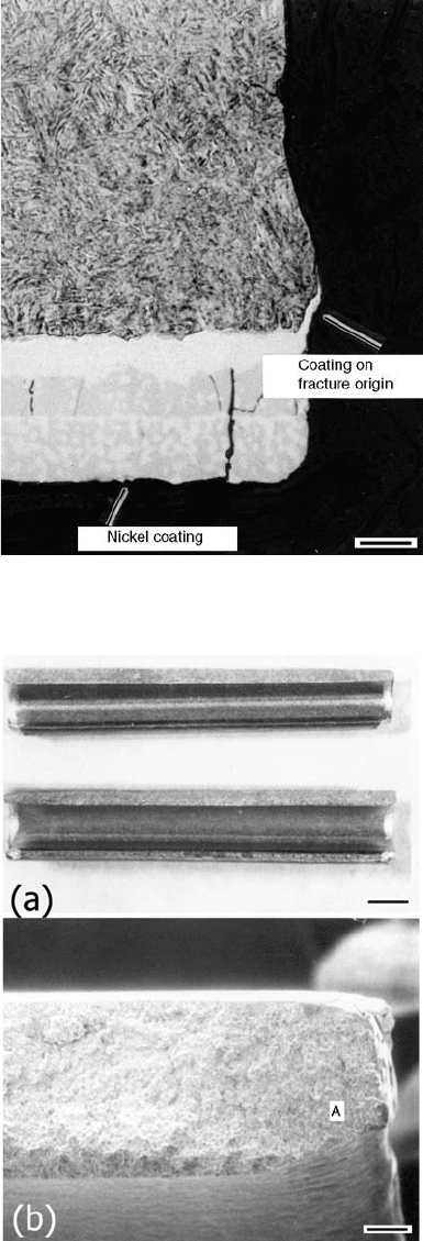
An SEM was used to examine the fracture
surface and to document the mode of failure.
Figure 19 shows typical SEM fractographs made
of the fracture surface. The fracture topography
at the origin was intergranular. The dimensions
of the origin were 0.5 mm wide by 0.19 mm
deep (0.02 in. by 0.0075 in.). Away from the
origin was a static rupture area, which was
characterized by dimples. Approximately 85%
across the thickness, an arrest mark was present.
As shown in Fig. 19, the fracture topography in
the arrest was intergranular. Past this zone to the
edge of the specimen, the fracture topography
consisted of dimples (static rupture).
Hardness measurements were made on the
piston rod cylinder. The hardness was 54 HRC,
and this met the hardness requirement of 53 to 55
HRC.
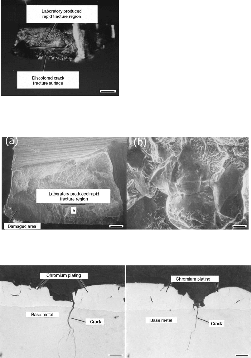
Fig. 12 Discoloration of the fracture surface (330 mm)
Fig. 13
Topographic features of the fracture surface as observed by the SEM. (a) Overall view of the fracture surface (111 mm).
(b) Intergranular fracture observed on the fracture surface (10 mm)
Fig. 14
Metallographic examination of cracks evident in the flange of the main landing gear lever attach pin, showing loss of
chromium at cracks (20 mm)
358 / Failure Analysis of Heat Treated Steel Components
Name ///sr-nova/Dclabs_wip/Failure_Analysis/5113_351-393.pdf/Chap_11/ 18/8/2008 3:45PM Plate # 0 pg 358
A hydrogen analysis was conducted on the
piston rod cylinder. The hydrogen content was
determined to be 2.3 ppm. This amount of hy-
drogen is considered sufficient to cause hydro-
gen embrittlement (Ref 5).
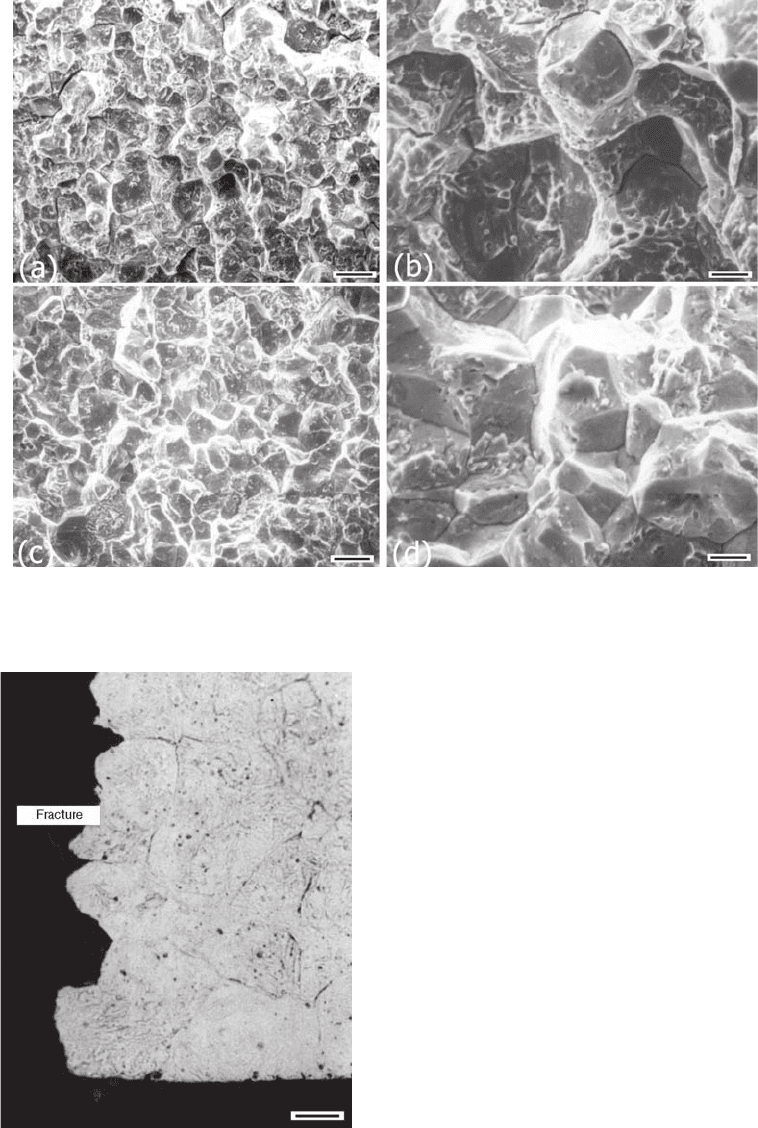
A metallographic specimen, section 1-1, was
removed at the origin location shown in Fig. 19.
The specimen was prepared using standard
metallographic techniques. The microstructure
at the origin is shown in Fig. 20. The micro-
structure of the steel, which consisted of tem-
pered martensite, was normal.
The plating at the origin consisted of three
distinct layers. The layers were subjected to an
energy-dispersive x-ray analysis. The outermost
two layers consisted essentially of nickel and
phosphorus, whereas the inner layer consisted of
nickel and iron. The outermost two layers con-
tained cracks, and the inner layer did not. Also
evident in the micrograph is plating that had
covered a small part of the fracture surface. This
gave evidence that a crack was present prior to
plating or prior to the heating of the plating,
which occurred during swaging.
A single intergranular origin was associated
with the fracture surface, and this origin was
relatively clean. These factors suggest a delayed
mode of failure, as occurs in a hydrogen
embrittlement failure. The bulk hydrogen was
analyzed to be 2.3 ppm; this concentration
would most likely be higher at the crack tip.
The intergranular origin was separated from
the intergranular arrest zone by a ductile rupture
region, indicating that the crack had propagated
in a ductile manner before arresting. Hydrogen
most likely diffused to and concentrated at the
crack tip, which caused the intergranular arrest
region to occur. The crack then propagated to
failure by ductile rupture.
Based on the results of this investigation, it is
concluded that the MLG linear actuating piston
rod cylinder failure was most likely due to
hydrogen embrittlement.
Failure Analysis of AISI 420 Stainless
Steel Roll Pin
Several failures of AISI stainless steel roll
pins were reported. This pin is a standard part
and is used to hold pin components together by
expanding after compression. The pin is manu-
factured from AISI 420 stainless steel and is heat
treated to 46 to 55 HRC.
Figure 21 shows the as-received failed roll
pin. The fracture extended the length of the pin.
An SEM was used to examine the fracture
surface of the service failure and a laboratory-
created overload failure from the same lot of
material. Figure 22 shows the results of the SEM
examination. In this figure, the topology of
the fractures was intergranular, with some dim-
ples present. This failure mechanism indicated
that the failure was due to overload (static
rupture).
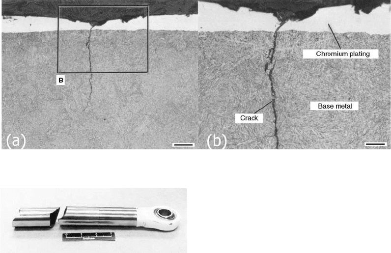
Fig. 15 Micrographs showing the morphology of the cracks. (a) Overall view (50 mm). (b) Closeup of crack (20 mm)
Fig. 16
As-received main landing gear linear actuating
piston rod cylinder
Case Studies of Steel Component Failures in Aerospace Applications / 359
Name ///sr-nova/Dclabs_wip/Failure_Analysis/5113_351-393.pdf/Chap_11/ 18/8/2008 3:46PM Plate # 0 pg 359
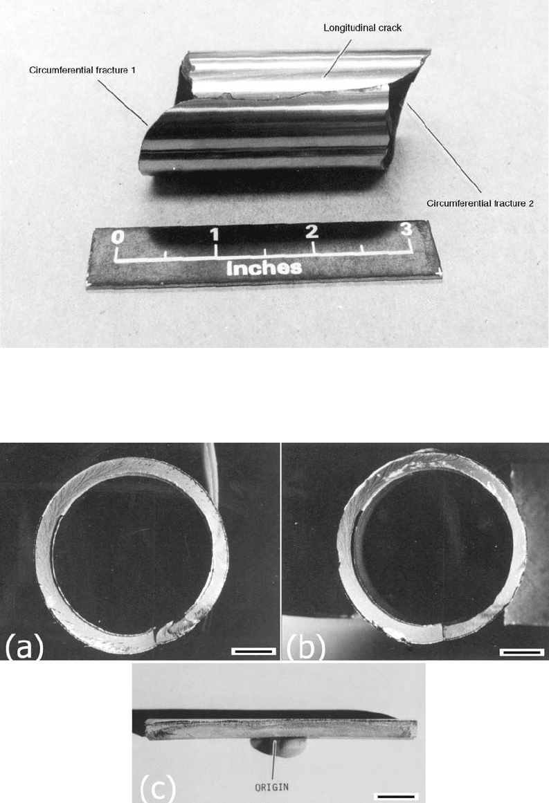
Fig. 17 Appearance of longitudinal crack in the main landing gear linear actuating piston rod cylinder
Fig. 18 Fracture surfaces. (a) Circumferential crack 1 (4.3 mm). (b) Circumferential crack 2 (4.3 mm). (c) Longitudinal crack (5 mm)
360 / Failure Analysis of Heat Treated Steel Components
Name ///sr-nova/Dclabs_wip/Failure_Analysis/5113_351-393.pdf/Chap_11/ 18/8/2008 3:46PM Plate # 0 pg 360
Hardness measurements were made on the
roll pin to verify the heat treated condition.
The hardness of the roll pin was measured to
be 49 HRC, which met the hardness requirement
of 46 to 55 HRC.
A metallographic specimen was prepared
through the fracture surface. The specimen was
prepared using standard metallographic tech-
niques. The microstructure (Fig. 23) consisted
of tempered martensite, with carbides out-
lining the prior-austenitic grain boundaries.
This is not a typical microstructure for quen-
ched and tempered AISI 420 stainless steel
(Ref 2).
Generally, because of their high harden-
ability, martensitic stainless steels can be quen-
ched in either oil or air. Oil quenching ensures
maximum ductility and corrosion resistance. Air
Fig. 19
SEM fractographs documenting the appearance of the fracture surface. (a) Origin location (670 mm). (b) View of box A
showing fracture origin. (c) Location A (5 mm). (d) Location B (2 mm). (e) Location C (5 mm). (f) Location D (2 mm)
Case Studies of Steel Component Failures in Aerospace Applications / 361
Name ///sr-nova/Dclabs_wip/Failure_Analysis/5113_351-393.pdf/Chap_11/ 18/8/2008 3:46PM Plate # 0 pg 361
quenching may cause decreases in ductility and
corrosion resistance. If slow cooled or an
inadequate quench through the critical range
of 870 to 540
C (1600 to 1000
F), this steel
will precipitate carbides at the grain boundaries
(Ref 2). Because of the presence of the inter-
granular carbides, it is likely that this part
experienced an inadequate quench.
Based on the results of this investigation, it
was thought that the failure mechanism was
overload, with limited ductility caused by
improper quenching during heat treatment.
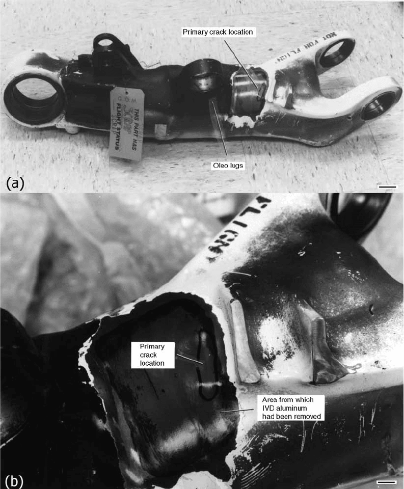
Failure Analysis of a Main Landing
Gear Lever
The MLG lever was removed from service
after a hard carrier landing. Multiple cracks
developed during removal of the ion vapor-
deposited (IVD) aluminum with sodium hydro-
xide to analyze for residual stresses by x-ray
diffraction.
The lever was machined from 300M steel
forging into a hollow configuration, machined,
then heat treated to a tensile strength level of
1930 to 2070 MPa (280 to 300 ksi). The lever
was then IVD coated on the outside.
Figure 24 shows the failed MLG lever as
received for examination. The location of a
primary crack and a series of secondary cracks,
which were between the up-latch and oleo lugs,
is also shown in Fig. 24. The primary crack was
approximately 23 mm (0.9 in.) long and is
shown in Fig. 24.
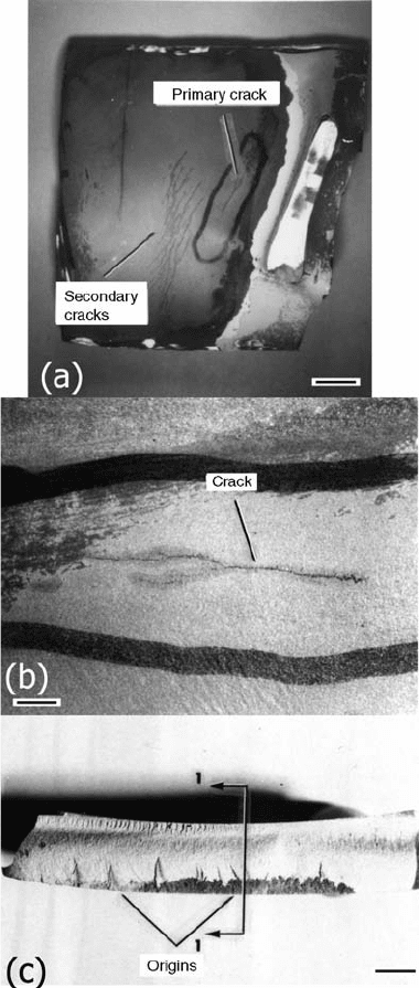
The primary crack was opened, and the frac-
ture surfaces were examined visually and at up
to 50 · magnification using a stereomicroscope.
Figure 25 shows a macrograph of the fracture
surface. Also shown in Fig. 25 are the appear-
ances of origins (some of which were dis-
colored), which were located on the outside
surface of the lever. The origin areas had a
faceted appearance, which indicate a delayed
mode of failure, that is, stress-corrosion crack-
ing or hydrogen embrittlement (Ref 6).
An SEM was used to examine the fracture
surface. Figure 26 shows SEM fractographs
documenting the topographic features of the
fracture origins. The fracture topography was
intergranular, which is indicative of a delayed
mode of failure.
The wall thickness at the origin location was
measured to be 5.8 mm (0.229 in.). The drawing
Fig. 20 Microstructure at fracture origin (12.5 mm)
Fig. 21
As-received 420 roll pin. (a) Visual view of
as-received roll pin (2.5 mm). (b) SEM view of
as-received roll pin (200 mm)
362 / Failure Analysis of Heat Treated Steel Components
Name ///sr-nova/Dclabs_wip/Failure_Analysis/5113_351-393.pdf/Chap_11/ 18/8/2008 3:46PM Plate # 0 pg 362
requirements for the maximum and minimum
wall thicknesses were 5.33 and 4.45 mm (0.210
and 0.175 in.), respectively. Therefore, the
drawing requirement was exceeded by 0.48 mm
(0.019 in.).
Hardness measurements were made on the
lever to verify heat treatment. The hardness of
the lever was 54.2 HRC, and this met the hard-
ness requirement of 53 to 55 HRC.
Hydrogen analyses conducted on the lever
yielded values of 3.0, 4.6, 3.4, and 3.5 ppm. The
average of the four values was 3.63 ppm, which
is considered high enough to produce a hydro-
gen embrittlement failure.
A metallographic specimen was removed
through the fracture origin area. The specimen
was prepared using standard metallographic
techniques. Figure 27 shows the microstructure
of the specimen. The microstructure of the lever
was tempered martensite, and this is normal for
a quenched and tempered high-strength, low-
alloy steel.
Based on the results, it is thought that the
cracks formed in the MLG lever as a result of
Fig. 22
SEM examination of the failed roll pin and laboratory-produced overload fractures. (a) Location A of the service failure
(20 mm). (b) Location A of the service failure showing intergranular fracture with some dimples (5 mm). (c) Laboratory-
produced overload failure showing intergranular fracture (20 mm). (d) Laboratory-produced failure showing intergranular fracture with
dimples (5 mm). Compare to (b)
Fig. 23
Microstructure of failed roll pin. Micro structure
consists of tempered martensite with carbides de-
corating the prior-austenite grain boundaries (10 mm)
Case Studies of Steel Component Failures in Aerospace Applications / 363
Name ///sr-nova/Dclabs_wip/Failure_Analysis/5113_351-393.pdf/Chap_11/ 18/8/2008 3:46PM Plate # 0 pg 363
the application of sodium hydroxide to remove
the IVD coating in addition to the residual
stresses present as a result of the hard carrier
landing. It is likely that accelerated stress-
corrosion cracking occurred because of the high
residual stresses and electrolyte.
Failure Analysis of an Inboard Flap
Hinge Bolt
An inboard flap hinge bolt was found to be
failed after 286.5 flight hours. The bolt had been
machined from 4330V-modified steel bar and
Fig. 24
Appearance of the main landing gear lever showing the location of the primary and secondary cracks. (a) Overall view
(33 mm). (b) Location of primary and secondary cracks at site of ion vapor deposit (IVD) removal (10 mm)
364 / Failure Analysis of Heat Treated Steel Components
Name ///sr-nova/Dclabs_wip/Failure_Analysis/5113_351-393.pdf/Chap_11/ 18/8/2008 3:46PM Plate # 0 pg 364
heat treated to the 1515 to 1655 MPa (220 to
240 ksi) tensile strength range. A nut with the
bolt was machined from 4140 steel bar heat
treated to the 1240 to 1380 MPa (180 to 200 ksi
tensile strength range.
Figure 28 shows the inboard flap hinge bolt
and nut as received for examination. The bolt
was approximately 102 mm (4 in.) long. The
bolt consisted essentially of the shank, which
was approximately 23 mm (0.9 in.) in diameter
and 64 mm (2.5 in.) long, and a threaded por-
tion, which was 23 mm (0.9 in.) in length with
thread type 0.5000-20 UNJF-3A THD in accor-
dance with MIL-S-8879. The unthreaded por-
tion of the bolt was chromium plated, while the
threaded portion was aluminum IVD coated.
The fracture had occurred at the transition of the
shank to the threaded portion of the bolt. The
fracture surface was examined visually and at up
to 30 · magnification using a stereomicroscope.
Figure 29 shows a macrograph of the fracture
surface. Fracture ridges emanated from an origin
that was located on the outer diameter surface
of the bolt at the location shown in Fig. 29.
The origin exhibited a reflective, intergranular
appearance. Apparent corrosion products were
also observed on the fracture surface.
Residual stresses were measured on the sur-
face of the bolt at locations 1 and 2, shown in
Fig. 28. The residual stresses were measured
using an x-ray residual-stress analyzer. Prior to
measuring the residual stresses, the chromium
plating (location 1) and the aluminum IVD
coating (location 2) were removed. The residual
stress measured at location 1 was 790+
100 MPa (–115+15 ksi), which indicated that
this area was properly shot peened as required
according to the engineering drawing. The resi-
dual stress measured at location 2 was 140+
100 MPa (20+15 ksi). This indicated that
this area was not shot peened. The engineering
drawing does not require this location to be shot
peened.
An SEM was used to examine the fracture
surface and to document the topographic fea-
tures. Figure 30 shows SEM fractographs taken
of the fracture surface. The fracture topography
at the origin was intergranular. The intergranular
topography extended for approximately
3
/
4
of
the way across the fracture surface, at which
point dimples indicative of ductile rupture were
present.
A laboratory-produced failure yielded a struc-
ture that consisted only of dimples.
The corrosion products on the service failure
fracture surface were subjected to an energy-
dispersive x-ray analysis. Calcium, potassium,
magnesium, and chlorine were identified as
being present.
Rockwell hardness measurements were made
on the inboard flap hinge bolt to verify heat
treatment condition. The hardness of the bolt
averaged 46 HRC. This met the hardness
Fig. 25
Appearance of primary crack removed from part.
(a) Region of primary crack where ion vapor-
deposited coating had been removed (13 mm). (b) Primary crack
showing branching (2 mm). (c) Fracture surface of crack after
opening (3 mm)
Case Studies of Steel Component Failures in Aerospace Applications / 365
Name ///sr-nova/Dclabs_wip/Failure_Analysis/5113_351-393.pdf/Chap_11/ 18/8/2008 3:46PM Plate # 0 pg 365