Canale L.C.F., Mesquita R.A., Totten G.E. Failure Analysis of Heat Treated Steel Components
Подождите немного. Документ загружается.

with shades of black and brown, as can be pro-
duced by heating the steel. The color brown
corresponds to the temper color, which is pro-
duced by heating steel to approximately 238
C
(460
F) in air and cooling to room temperature.
Chromium plating was observed on the outer
diameter surface of the gear. There were no
shear lips evident around the periphery of the
fracture surface. Fracture ridges emanated from
origins located on the inner diameter edge, and
the fracture surface exhibited a faceted appear-
ance indicative of a brittle intergranular failure.
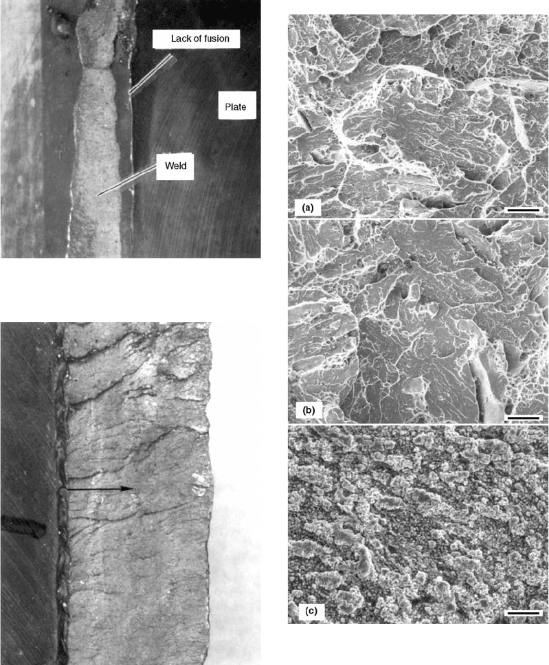
Fig. 48 Typical lack of fusion area
Fig. 49 Direction of fracture propagation
Fig. 50
SEM fractographs documenting the topographic
features of the failed weldment. (a) Location A
showing overload features. (b) Location B showing overload
features. (c) Location C showing weld defect features. Original
magnification: 1200·
376 / Failure Analysis of Heat Treated Steel Components
Name ///sr-nova/Dclabs_wip/Failure_Analysis/5113_351-393.pdf/Chap_11/ 18/8/2008 3:47PM Plate # 0 pg 376
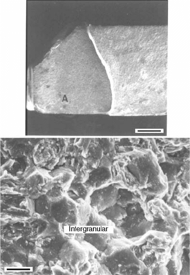
An SEM was used to examine the fracture
surface and to document the mode of failure.
Figure 54 shows SEM fractographs made at a
typical fracture origin. The fracture topography
was intergranular, which is indicative of a brittle
mode of failure (Ref 3). No defects were ob-
served that could be associated with the cause
of the fracture.
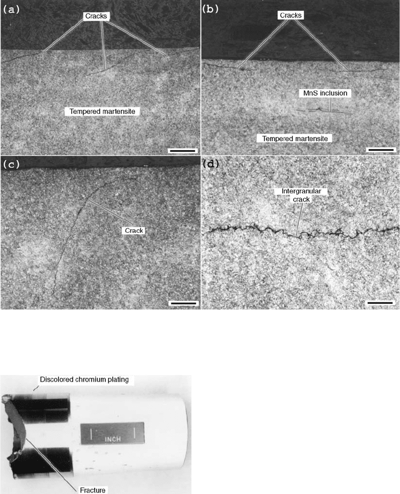
A metallographic specimen was removed
at the location shown in Fig. 52. The specimen
was prepared using standard metallographic
techniques. Figure 55 shows the microstructure
(tempered martensite) and typical cracks that
were present. The cracks were intergranular,
and an oxide was present in the cracks. The
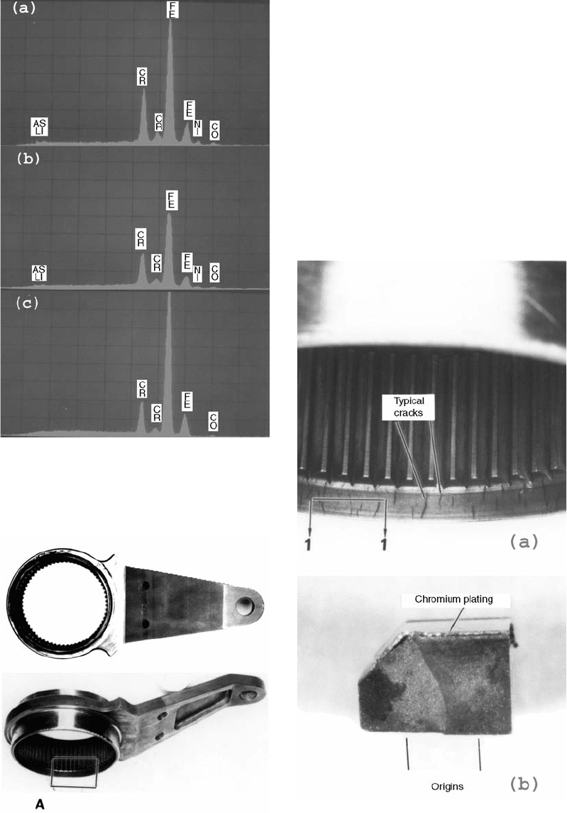
Fig. 51
Energy-dispersive spectrographs of failed weld and
base material. (a) Location A weld metal. (b) Loca-
tion B weld metal. (c) Location C weld metal
Fig. 52
As-received internal spur gear showing location of
cracks
Fig. 53
Macrographs of (a) magnetic particle indications of
cracks and (b) opened crack revealing the fracture
surface
Case Studies of Steel Component Failures in Aerospace Applications / 377
Name ///sr-nova/Dclabs_wip/Failure_Analysis/5113_351-393.pdf/Chap_11/ 18/8/2008 3:47PM Plate # 0 pg 377
morphology of the cracks is typical of grinding
cracks (Ref 8).
A hydrogen analysis conducted on the inter-
nal gear yielded a value of 1.85 ppm, which is
not considered to be high enough to cause
hydrogen embrittlement.
Hardness measurements were made on the
internal gear to verify the heat treat condition.
The hardness of the gear near the observed
cracking was 44 HRC. This hardness value was
below the drawing hardness requirement of 50
to 53 HRC. The bulk hardness of the gear was
51 HRC.
The lower-than-expected hardness at the
crack initiation sites indicates that there was
some event that caused excessive local heating
of the microstructure. Because of the nature of
the part and typical manufacturing sequence, it
is likely that the grinding cracks occurred as a
result of aggressive grinding. Based on the
results of this investigation, it is concluded that
the internal spur gear failed due to aggressive
grinding.
Main Landing Gear Axle
During taxi, the MLG axle separated. The
axle had been installed for only 90 days, with a
total flight time of 62 h. The axle was fabricated
from 300M high-strength, low-alloy steel.
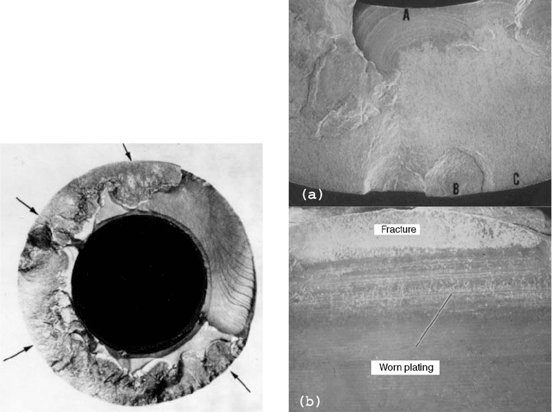
Shown in Fig. 56 is the as-received failed
MLG axle. Also shown in Fig. 56 is the location
of the fracture, which occurred adjacent to a
chromium- and cadmium-plated area. Also
shown in Fig. 56 is a worn (discolored) area of
chromium plating.
The fracture surface was examined visually
and at up to 50 · magnification using a stereo-
microscope. Figure 57 is a macrograph of the
fracture surface. Shown in Fig. 58 is an SEM
photograph of the wear that had removed the
protective plating adjacent to the fracture sur-
face. Multiple origins were located around the
periphery of the axle. Faceted areas character-
istic of an intergranular, delayed mode of failure
had progressed through approximately 80% of
the thickness. Fatigue propagated from the ends
of the intergranular areas, with several areas of
the wall being totally penetrated by the fatigue.
The relatively large intergranular areas and the
irregular shape of the intergranular area are
indicative of stress corrosion.
An SEM was used to examine the fracture
surface and to document the mode of failure.
Shown in Fig. 59 are SEM fractographs doc-
umenting topographic features, that is, inter-
granular topography and fatigue striations, on
the fracture surface. From the ends of the inter-
granular area, fatigue propagated through the
wall thickness. Also documented in Fig. 59 are
the lack of plating at a fracture origin and cor-
rosion products, which were present at the
intergranular fracture origins. The lack of plat-
ing and the presence of corrosion products are
indicative of a stress-corrosion failure. Also
shown in Fig. 59 is an area where the chromium
was intact.
The hardness of the axle was determined to be
53.9 HRC. This met the hardness requirement of
53 to 55 HRC.
A chemical analysis by atomic absorption
verified that the MLG axle was fabricated from
300M steel.
A metallographic specimen was prepared
through a typical fracture origin on the axle. The
specimen was prepared using standard metallo-
graphic techniques. As determined from the
metallographic specimen, the thickness of the
chromium plating was approximately 0.06 mm
Fig. 54
SEM fractographs showing the topographic features
of a typical fracture origin. (a) Fracture surface. Ori-
ginal magnification: 20·. (b) Location A showing intergranular
fracture. Original magnification: 3000·
378 / Failure Analysis of Heat Treated Steel Components
Name ///sr-nova/Dclabs_wip/Failure_Analysis/5113_351-393.pdf/Chap_11/ 18/8/2008 3:47PM Plate # 0 pg 378
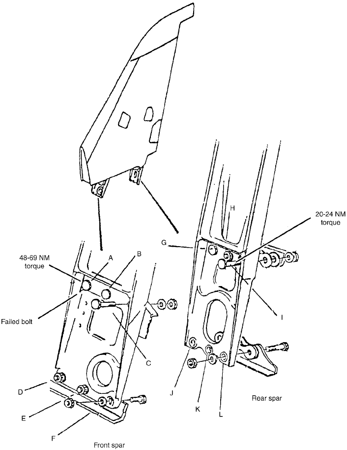
(0.0024 in.). Shown in Fig. 60 is the micro-
structure of the axle at a typical fracture origin.
The chromium plating ended approximately
1.6 mm (0.062 in.) from the origin. The hard-
ness of the light, discolored area at the
chromium runout was 58.4 HRC, which exceeds
the hardness requirement of 53 to 55 HRC. Past
the chromium runout, the part was supposed to
be cadmium plated. However, past the chro-
mium runout to the origin, no plating was pre-
sent. The wear documented in Fig. 60 had
removed the protective cadmium plating from
this location. This allowed corrosion to occur.
Shown in Fig. 61 is a secondary branch crack
characteristic of stress corrosion. This micro-
graph also shows the chromium plating that had
been penetrated. Documented in Fig. 62 is the
appearance of the crack (unetched) after further
polishing. Note the worn (missing) chromium.
A hydrogen analysis conducted on the axle
yielded hydrogen content of 4.2 ppm, which is
relatively high and considered high enough
to cause hydrogen embrittlement (Ref 4). This
hydrogen is in the form of atomic hydrogen and
can be generated in corrosion reactions and then
absorbed by steel.
Fig. 56 As-received failed axle
Fig. 55
Micrographs showing the appearance of the cracks and microstructure. (a) Surface cracking evident. Original magnification:
50·. (b) Surface cracking and MnS inclusions. Original magnification: 100·. (c) Extended surface crack. Original magni-
fication: 100 · . (d) Intergranular crack along prior-austenite grain boundaries. Original magnification: 200·
Case Studies of Steel Component Failures in Aerospace Applications / 379
Name ///sr-nova/Dclabs_wip/Failure_Analysis/5113_351-393.pdf/Chap_11/ 18/8/2008 3:47PM Plate # 0 pg 379
Based on the results observed, it was deter-
mined that the MLG axle failed due to stress-
corrosion cracking. The protective cadmium
plating had been worn away, allowing corrosion
to occur at locations where the cadmium was no
longer present.
Nondestructive Testing and Failure
Analysis of Fin Attach Bolts after
Full-Scale Fatigue Testing
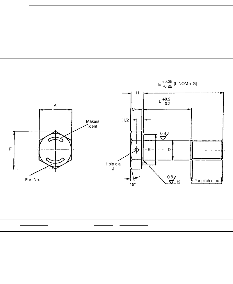
During the inspection, after the first lifetime
of fatigue testing, one aft fin attach bolt was
found to have broken. Five additional bolts were
found to have crack indications. The location of
the bolts and the nomenclature used for identi-
fication of these bolts are shown in Fig. 63. The
failed bolt (bolt A) and the additional five bolts,
identified as B, C, G, H, and I, were submitted to
the laboratory to determine if ultrasonic testing
would be a suitable field inspection technique
for this application and to examine the failed bolt
and cracked bolts to determine the failure
modes.
The specification requirements for these bolts
are for a cadmium-plated, forged hex head
metric bolt that has a close tolerance shank.
The material can be any of four material
specifications: BS S147, S148, S149, or S158.
The compositions of these steels are shown
in Table 2. These steels are heat treated to
a minimum tensile strength of 1100 MPa
(160 ksi) minimum. The threads and the head-
to-shank fillet radius are rolled after heat treat-
ment. Machining of the fillet radius is not
permitted. The specified dimensions are shown
in Fig. 64 and Table 3.
The failed bolt and the additional bolts were
examined using nondestructive testing, visual
examination, scanning electron microscopy,
metallography, and analytical chemistry. The
hardness of the parts was also measured.
Nondestructive testing was performed on
the submitted bolts to determine if ultrasonic
inspection is a suitable field inspection method.
Magnetic particle inspection was used as a
confirmation of the ultrasonic inspection
method.
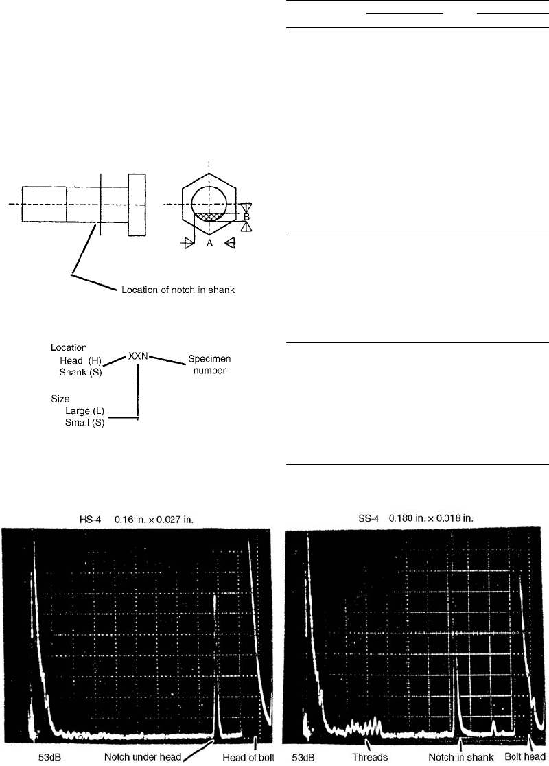
Ultrasonic reference standards were fabri-
cated from AN-8 and AN-6 pan stock bolts.
These bolts were machined so that the head
thickness and lengths were similar to the test
articles. Notches were cut into the bolts at the
head radius and at the midpoint length of the grip
Fig. 58
Overall view at origin. (a) Worn cadmium plating at
origin. (b) SEM photograph of fracture surface
Fig. 57
Macrograph of fracture surface of the failed axle.
Typical fracture origins are shown at arrows.
380 / Failure Analysis of Heat Treated Steel Components
Name ///sr-nova/Dclabs_wip/Failure_Analysis/5113_351-393.pdf/Chap_11/ 18/8/2008 3:47PM Plate # 0 pg 380
on the shank. The dimensions of the reference
standards and notches are noted in Fig. 65 and
Table 4. While every attempt was made to make
the manufactured notches at the head-to-shank
fillet radii and the shank identical, it was not
always possible because of manufacturing
Fig. 59
SEM fractographs documenting the fracture features found at the origin. (a) Fatigue striations emanating from the origin
(200 mm). (b) Intergranular fracture at origin (location A, 50 mm). (c) Intergranular fracture and corrosion products found at
the origin (13 mm). (d) Intergranular fracture found at interface between chromium plating and steel (50 mm)
Fig. 60
Lack of plating at fracture origin. (a) Overall view of microstructure through fracture origin (500 mm). (b) Lack of plating at
fracture origin (50 mm)
Case Studies of Steel Component Failures in Aerospace Applications / 381
Name ///sr-nova/Dclabs_wip/Failure_Analysis/5113_351-393.pdf/Chap_11/ 18/8/2008 3:48PM Plate # 0 pg 381

tolerances. The ultrasonic inspection was con-
ducted with an ultrasonic transducer (20 MHz;
3.18 mm, or 0.125 in., in diameter). The delay
line was removed for this application. The
instrument settings are noted in Table 5. The
sensitivity of the instrument was adjusted so that
an 80% signal response was obtained from the
notch under the bolt head of the reference stan-
dard (4.17 mm, or 0.164 in., long; 0.686 mm,
or 0.027 in., deep) and a notch on the shank of
the machined reference standard (4.57 mm, or
0.180 in., long; 4.57 mm, or 0.18 in., deep). Sig-
nal responses for the reference standards are
shown in Fig. 66. Each of the submitted bolts
was inspected with an additional 6 dB of gain to
increase the sensitivity of the inspection. Signal
responses for each of the bolts are shown in
Fig. 67. The ultrasonic inspection showed that a
crack indication was present at the shank-to-
head fillet radius of bolt C. No crack indications
were found in the other bolts.
The submitted bolts were inspected using
standard magnetic particle inspection techni-
ques. The results indicate that bolts C, G, and I
had circumferential crack indications at the
shank-to-head fillet radius. Bolt I had a cir-
cumferential crack indication around the shank
of the bolt. The magnetic particle indications are
shown in Fig. 68.
After nondestructive testing, bolts C, G, and B
were inspected visually. The as-received bolts
are shown in Fig. 69. After inspection, the cracks
Fig. 61
Secondary branch cracking observed. (a) Overall
etched microstructure. (b) Location E, showing
cracking on prior-austentite grain boundaries. (c) Location F,
showing voids in chromium plating and associated cracking
Fig. 62
Unetched micrograph showing branch cracking and void in chromium plating. (a) Overall view of secondary crack
(500 mm). (b) Location G showing void in chromium plating and associated cracking (50 mm). (c) Location H showing
cracking along prior-austenite grain boundaries (50 mm)
382 / Failure Analysis of Heat Treated Steel Components
Name ///sr-nova/Dclabs_wip/Failure_Analysis/5113_351-393.pdf/Chap_11/ 18/8/2008 3:48PM Plate # 0 pg 382
indicated by magnetic particle inspection were
exposed. This was accomplished by centering
the threaded portion of the bolts in the chuck of a
lathe and drilling a small pilot hole. A larger drill
bit was then used to drill the center of the bolt,
leaving a wall thickness of approximately
0.76 mm (0.030 in.). Using a hacksaw, a small
saw cut was made opposite to the crack. The
head of the bolt was held in a vise, and the shank
of the drill bit was inserted into the hole of the
bolt to support the bolt shank. Using the drill bit,
the bolt was bent away from the crack indi-
cation, keeping the crack faces in tension. The
exposed crack was then analyzed.
Bolt B showed no crack indications, using
ultrasonic inspection or magnetic particle
inspection. This bolt showed significant cir-
cumferential scoring around the periphery of the
Fig. 63 Schematic of bolt location and nomenclature used
Case Studies of Steel Component Failures in Aerospace Applications / 383
Name ///sr-nova/Dclabs_wip/Failure_Analysis/5113_351-393.pdf/Chap_11/ 18/8/2008 3:48PM Plate # 0 pg 383
shank, at approximately the midpoint of the
shank. Minor deformation at the corners of the
bolt head was detected. Because no crack in-
dication was seen by nondestructive testing
(NDT), no additional work was performed on
this bolt.
Bolt C showed a highly polished shank sur-
face, with a circumferential scoring line in the
same approximate location as bolt B. Some
rounding of the head corners was evident. No
identifying mark or part numbers were stamped
on the head of the bolt. After exposing the crack,
Table 2 Allowable chemistries of the submitted bolts
Element
Allowable composition range of British Specifications, wt%
BS S147 BS S148 BS S149 BS S158
Max Min Max Min Max Min Max Min
C 0.38 0.43 0.36 0.41 0.38 0.43 0.22 0.29
Si 0.20 0.35 0.15 0.35 0.20 0.35 0.15 0.35
Mn 0.75 1.00 0.60 0.90 0.65 0.85 0.50 0.80
P ... 0.025 ... 0.025 ... 0.025 ... 0.020
S ... 0.020 ... 0.025 ... 0.020 ... 0.015
Cr 0.40 0.60 0.50 0.80 0.70 0.90 0.90 1.20
Mo 0.20 0.30 ... ... 0.20 0.30 0.15 0.25
Ni 0.60 0.70 1.10 1.50 1.65 2.0 ... 0.30
Fig. 64 Schematic of bolt dimensions
Table 3 Allowable bolt dimensions
Size code
Thread
A tolerance B min
CD
F
G
HR
JDiameter Pitch Max Min Max Min Min +0.00.3 +0.00.2
03 M3 0.5 5.5 4.88 0.4 0.2 2.990 2.965 6.08 6.0 2.0 0.4 ...
04 M4 0.7 7.0 6.38 0.5 0.2 3.990 3.965 7.74 7.6 2.5 0.4 1.0
05 M5 0.8 8.0 7.38 0.5 0.2 4.990 4.965 8.87 8.5 3.0 0.5 1.2
06 M6 1.0 10.0 9.28 0.5 0.2 5.990 5.965 10.95 9.5 3.5 0.7 1.6
08 M8 1.25 13.0 12.28 0.5 0.2 7.987 7.962 14.26 12.4 4.5 0.7 2.0
10 M10 1.5 17.0 16.08 0.6 0.3 9.987 9.962 18.90 14.8 5.0 0.8 2.0
12 M12 1.5 19.0 18.17 0.6 0.3 11.984 11.959 21.10 15.5 6.0 0.9 2.0
14 M14 1.5 22.0 21.17 0.6 0.3 13.984 13.959 24.49 17.5 7.0 1.0 2.0
16 M16 1.5 24.0 23.17 0.6 0.3 15.984 15.959 26.75 19.5 8.0 1.1 2.0
Note: All dimensions in millimeters
384 / Failure Analysis of Heat Treated Steel Components
Name ///sr-nova/Dclabs_wip/Failure_Analysis/5113_351-393.pdf/Chap_11/ 18/8/2008 3:48PM Plate # 0 pg 384
the resulting fracture surface was examined
(Fig. 70). The fracture surface of crack C had the
characteristic ratchet marks or shear ridges that
indicate multiple initiation sites along the outer
edge of the bolt. The shape and appearance of
the fracture surface was indicative of fatigue.
Bolt G showed circumferential scoring
(Fig. 69), and some rounding of the head corners
was evident. After the crack was exposed,
the resulting fracture surface was examined
Fig. 65
Sketch of reference standards used during ultrasonic
inspection
Table 4 Dimensions of reference standards
used for ultrasonic testing
Specimen
identification
AB
mm in. mm in.
HL1 12.4 0.487 5.66 0.223
HL2 10.1 0.399 2.39 0.094
HL3 7.70 0.303 1.37 0.054
HL4 5.99 0.236 0.81 0.032
HS1 9.47 0.373 3.96 0.156
HS2 7.82 0.308 1.98 0.078
HS3 6.50 0.256 1.17 0.046
HS4 4.16 0.164 0.69 0.027
HS5 2.46 0.097 0.15 0.006
SL1 12.3 0.485 5.87 0.231
SL2 11.2 0.440 3.40 0.134
SL3 8.13 0.320 1.52 0.060
SL4 5.82 0.229 0.81 0.032
SS1 8.97 0.353 3.18 0.125
SS2 7.65 0.301 2.24 0.088
SS3 5.16 0.203 0.76 0.030
SS4 4.57 0.180 0.46 0.018
SS5 2.82 0.111 0.18 0.007
Table 5 Ultrasonic inspection techniques
equipment settings
Tune 0
Reject Off
Gain 53 dB
Frequency 25 MHz
Video filter FW
Damping Minimum
Delay 0
Range 8.3
Velocity 1
Repetition rate 3
Fig. 66 Ultrasonic signal responses from the manufactured reference standards
Case Studies of Steel Component Failures in Aerospace Applications / 385
Name ///sr-nova/Dclabs_wip/Failure_Analysis/5113_351-393.pdf/Chap_11/ 18/8/2008 3:48PM Plate # 0 pg 385