Canale L.C.F., Mesquita R.A., Totten G.E. Failure Analysis of Heat Treated Steel Components
Подождите немного. Документ загружается.

composition that is facilitating martensitic trans-
formation. This must be differentiated from the
situation where the major cause of the crack is
that the heat treater quenched the part(s) more
severely than usual.
It is difficult to distinguish quench cracks due
to extreme quench severity from those due to
rich composition. However, it is easier to de-
termine whether the crack has an expected
geometry for a quench crack. In Fig. 24, the
crack is at the section change, which is a prime
location for a quench crack, as are sharp corners.
When examining a part to determine if rich
alloy/quench severity issues were at stake,
examine the crack surfaces for traces of temper
colors, including blues and browns. A dark
matte gray or black surface may indicate the
presence of an oxide-filled discontinuity that
simply opened due to thermal stresses rather
than a rich alloy/quench severity problem.
If temper colors are visible at the portion of
the crack surface nearest the part surface, it is
likely that one or more of the following factors
was present:
Quench was more severe than was appro-
priate
Alloy was richer than usual
Section change was more severe (for ex-
ample, the fillet radius was too sharp)
To confirm the suspicion of a “pure” quench
severity/rich composition-related quench crack,
it is advisable to confirm that the microscale
crack path is intergranular (usually SEM is
required). If a seam had been found at the
quench-opened crack, it would not be correct to
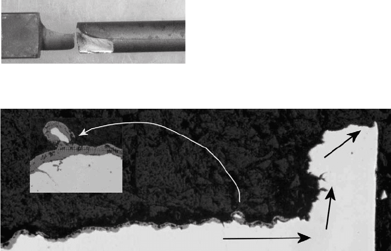
blame the heat treatment. Figure 25 shows an
interesting crack. There is a very heavy oxide
layer revealed by the cross section. The inset
shows a higher-magnification view of the seam
detail. There is a rounded particle that is totally
covered by a heavy, rounded oxide layer. The
crack surface does not have blue or brown
temper colors but was found to be a dark char-
coal black. This type of heavy oxide is unlikely
to have happened between when the part was
quenched (and presumably cracked) and when it
exited the temper furnace. Another unusual
feature of this crack is that it changed direction
multiple times (large arrows show crack growth
direction changes). The fact that these are not
predominantly intergranular cracks deals the
final blow to any theory stating that this crack
was due to a heat treating problem.
Some people wonder why it was not possible
to see the seam before it went into the heat
treating process. Many seams are tightly closed
or smeared over until the part experiences the
stresses of the heat treating operation. Limita-
tions of nondestructive testing methodology
may also play a role. In the case of a part with a
quench crack in a location that would not be
expected to have high stresses in quenching due
to differential cooling rates, the experienced
Fig. 24 Quench crack with typical geometry
Fig. 25
Oxide layer along a seam most likely present in the raw material. Original magnification: 50 · . Inset original magnification:
200 ·
102 / Failure Analysis of Heat Treated Steel Components
Name ///sr-nova/Dclabs_wip/Failure_Analysis/5113_87-109.pdf/Chap_02b/ 21/8/2008 10:51AM Plate # 0 pg 102
analyst looks for some type of discontinuity. The
discontinuity does not have to be very thick. This
example was particularly heavy, but even a very
thin oxide layer is enough to be the predominant
cause of the crack.
Macro- or microsegregation (otherwise
known as banding) are other raw material char-
acteristics that can interfere with the expected
outcome of a heat treating process. Figure 26
is a longitudinal cross section from a medium-
carbon piece of steel. If the low-carbon layer is
right at the surface, it may be difficult to meet a
minimum hardness specification.
Banding, or microsegregation, is not always
bad. It can make it easier for the crack to grow in
a particular direction, and that may be an
advantage for a particular application. Samurai
and Damascus swords from antiquity had basi-
cally banded microstructures with very desirable
characteristics. While banding is not necessarily
bad, it can cause some variation in the response
to the heat treatment.
If a material has intermittent coarse grains, it
may be easier to form martensite in the large
grains and pearlite, ferrite, or bainite in the
surrounding fine grains. Can the heat treater
create such a grain size distribution? This may
be possible by overheating.
However, it is also possible that the coarsen-
ing came from a subcritical amount of cold work
stored in the material. Normalizing the steel
prior to hardening may eliminate the nonuni-
form response to hardening, but the added cost
of normalization is often objectionable (Fig. 27).
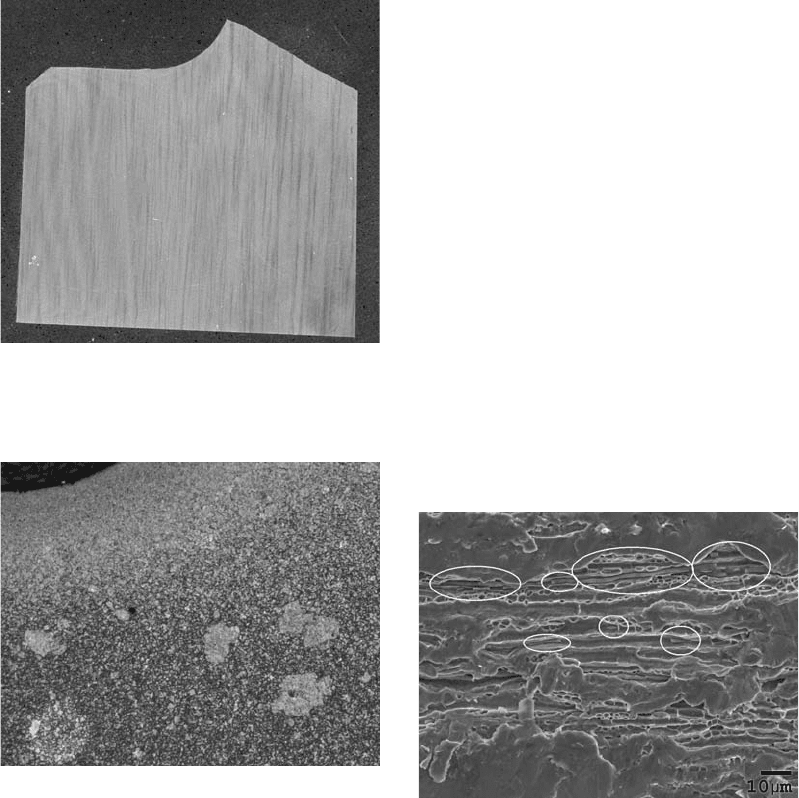
Another type of raw material characteristic
that can cause problems in some applications is
heavy bands of stringers. Figure 28 shows a
piece of steel that has long sulfide stringers in it,
which can act like a seam.
Figure 29 is of a wire product that was used in
a coil spring. The material was subject to tor-
sional loading. A longitudinal discontinuity in a
material that is subject to torsional loading can
create very high local shear stresses in the
longitudinal or radial directions. This is one
reason that seams are not allowed in critical
applications for spring wires. Decarburization is
not detected on the surface, but there is a heavy
decarburized layer on either side of an inclusion
of the shape characteristic of a seam. The heat
treatment is unlikely to create such a varying
thickness layer of oxide.
Fig. 26
Longitudinal cross section showing microsegreg-
ation. Original steel segment shown is approximately
2 cm wide.
Fig. 27
A few coarse grains in the core of a fine-grained
material that has been carburized are the only por-
tion of the core able to form martensite. Original magnification:
100 ·
Fig. 28
Scanning electron micrograph of sulfide stringers in a
piece of bar stock
Mechanisms and Causes of Failures in Heat Treated Steel Parts / 103
Name ///sr-nova/Dclabs_wip/Failure_Analysis/5113_87-109.pdf/Chap_02b/ 21/8/2008 10:51AM Plate # 0 pg 103
Component Characteristics
Figure 30 shows a cast steel product that was
quite uniformly carburized, except for the white
script features. The pattern looks very similar to
microsegregation between the dendrites and the
matrix. It would be very difficult for the heat to
overcome the initial segregation in the raw
material. This component may not perform as
well as a component with a uniform case. These
script features may make the case even more
brittle than usual. The heat treater can control the
carbon potential and the heating cycle. How-
ever, the heat treater cannot locally put fewer
carbon atoms into the steel at the locations that
already have too many. When performing fail-
ure analysis of steel components, analysts must
Fig. 29
Optical micrograph of an oxid e-lined seam in a
piece of steel wire
Fig. 30
Cast steel after carburizing. Original magnification:
100 ·
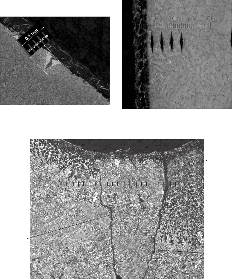
Dark etching
area possible
indication of
heat treating
problem
40
40
30
30
20
20
10
10
0
Unusual crack
shape
Oxide filled crack
Evidence of
pre-existing
discontinuities
Note multiple
cracks in one
thread root
Fig. 31 Thread root of a steel fastener. Original magnification: 100 ·
104 / Failure Analysis of Heat Treated Steel Components
Name ///sr-nova/Dclabs_wip/Failure_Analysis/5113_87-109.pdf/Chap_02b/ 21/8/2008 10:51AM Plate # 0 pg 104
always be on the lookout for the whole history of
the part that led up to the heat treating event.
Forging discontinuities are another situation
that could cause a problem. Figure 31 shows a
cross section of a threaded fastener with a locally
different compositional steel inclusion. Some-
thing unusual happened to create this feature.
Other problems relating to poor heat treating
or poor service outcome include many different
types of design details. Other chapters in this
book address these issues in greater detail. To
summarize, some areas of common oversight
include:
Materials selection
Heat treating process selection
Hardness level specification and range and
position on part for hardness test
Process details (batch or continuous
oven, etc.)
Heat treater’s familiarity with the size and
complexity of the part and the quality level
needed
Distortion control
Testing competence
Hardness scale selection
Frequency of part testing
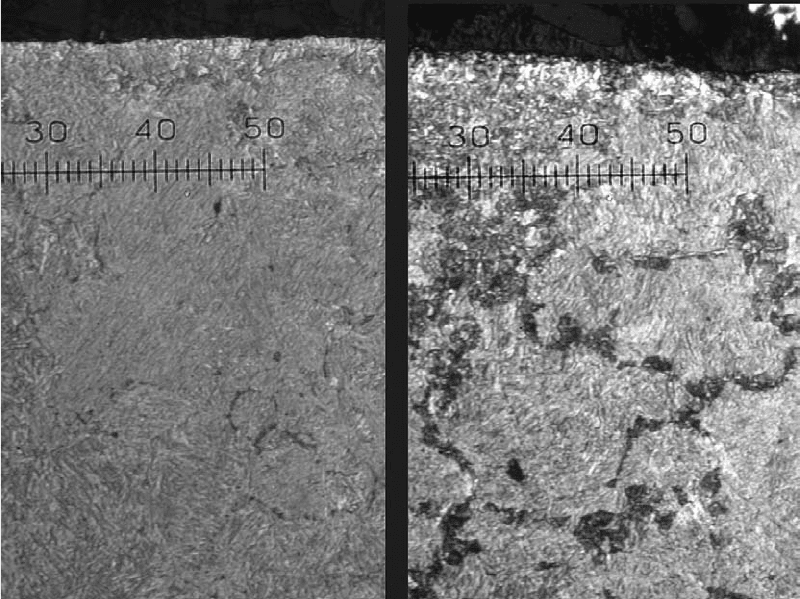
Figure 32 shows two micrographs at the same
magnification from the same component,
25 mm (1 in.) apart from each other. One of
them is virtually all martensite. In the other
location, there are wide grains of pearlite inter-
spersed between the martensite grains. There
was as much as 12 Rockwell C points difference
between the two microstructures. The designer
never indicated where to test the component!
This is a typical design issue.
Another common cause of disputes between
purchasers and providers of heat treating ser-
vices is that designers specify Rockwell tests
when there is no way to perform anything but a
Knoop or Vickers test. There are still many
newly minted engineering prints with case
depth specifications that are very unclear. There
are standard methods for specifying carburized,
induction-hardened, or carbonitrided case
depths, and it is helpful to use an industry
Fig. 32
Medium-carbon steel microstructures from the same component at two locations separated by approximately 25 mm (1 in.).
Each small scale division is 5 mm.
Mechanisms and Causes of Failures in Heat Treated Steel Parts / 105
Name ///sr-nova/Dclabs_wip/Failure_Analysis/5113_87-109.pdf/Chap_02b/ 21/8/2008 10:51AM Plate # 0 pg 105
standard when possible. The automotive manu-
facturers have done a good job of providing a
range of methods at a range of ease of testing. If
a standard method is not being used, it is often
difficult to determine the designer’s intent.
The specifications for 400-series stainless
steel can be particularly difficult for the average
mechanical designer to write. Many designers
specify 400-series stainless steel because they
want stainless, but they want to be able to heat
treat it to obtain higher hardness than standard
300-series annealed bar stock. For a number of
the 400-series grades, one must determine in
advance whether maximum strength or max-
imum corrosion resistance is desired. Two
totally different heat treating processes attain
those goals. The heat treater has no means of
guessing which characteristic is required.
What Are the Things That Can Go Wrong
in the Heat Treating Process?
This chapter has attempted to cover all the
aspects for which the heat treater should not be
blamed. What are the aspects for which the heat
treater may or should bear responsibility?
One approach is to say that heat treaters must
take responsibility for those aspects that are
specific to their equipment. These are details that
only the heat treater could know. Design engi-
neers specify materials and thus need to know
how to specify the type of testing and evaluation
required for application. A design engineer
cannot know how fast a load of parts will be
heated in a particular company’s individual
furnace. The design engineer cannot be expected
to know what type of fixturing may be necessary
to maintain required distortion levels in the
part. These are aspects the heat treaters must
know. The heat treaters must know what load
size can be treated in their own furnaces and how
the load should be distributed. The heat treaters
must understand the characteristics of the
interactions between their equipment and the
full range of part sizes and load sizes they are
processing.
Heat Treating Errors. Excessive heating
rate, excessive time at temperature, and exces-
sive temperature can lead to excessive distor-
tion. Excessive temperature can cause problems
with excessive autotempering. If a massive part
is heated to 75, 100, or more degrees hotter than
it needs to be to obtain the uniform austenite
required before quench, then all the extra
heat must be removed, which can make it diffi-
cult to create the desired martensite at all. Fur-
thermore, the extra heat may act to partially
temper the martensite that is present. Excessive
Fig. 33
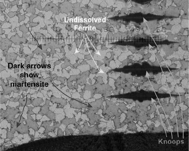
Undissolved ferrite and martensite in improperly specified and improperly induction-hardened medium-carbon steel part.
Each small scale division is 5 mm.
106 / Failure Analysis of Heat Treated Steel Components
Name ///sr-nova/Dclabs_wip/Failure_Analysis/5113_87-109.pdf/Chap_02b/ 21/8/2008 10:51AM Plate # 0 pg 106
heating can cause trouble in obtaining minimum
specified as-quenched hardness values. These
low as-quenched hardness characteristics may
or may not make a difference in the component
performance. However, when as-quenched
hardness tests are required, it is important to
know that excessive temperature may be a
cause.
Inadequate Heating Rate, Inadequate
Time at Temperature, and Inadequate Tem-
perature. Figure 33 shows the microstructure
of a part that was supposed to be induction
hardened. There is some martensite. The light
constituent is ferrite that never went into sol-
ution. The initial microstructure was probably a
mixture of ferrite and pearlite. The pearlite
transformed into martensite, but little of the
ferrite did. On quenching, the material produced
islands of martensite with islands of ferrite. The
irregular shapes of the ferrite islands are classi-
cal undissolved ferrite. This is not a typical
shape of ferrite grains formed on cooling.
Because of the severity of the consequences,
most of the common problems in heat treating
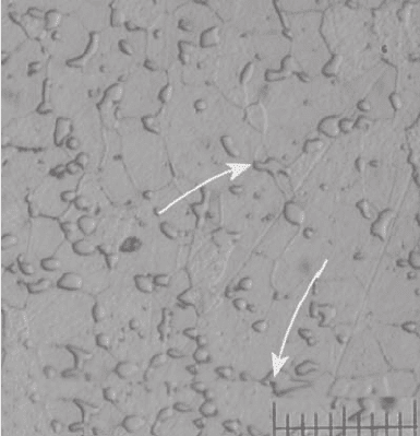
are related to hardening. Annealing can also be
done incorrectly. Figure 34 shows the micro-
structure of a steel that was supposed to be
spheroidized annealed. Spheroidization is a pro-
cess that may take 12, 15, or even 20 h at 600 to
700
C. Spheroidized annealed steel is generally
quite expensive. Its applications are usually
reserved for severe forming operations where
the added ductility is a necessity. The annealing
line management may be tempted to cut down
the process time to save money. The minimum
spheroidization that the material processor
believes will work is what is often provided.
In the case of varying incoming microstructures,
the part may not be as ductile as usual. Examine
the situation where the forming process creates a
crack that was undetected, and then the part is
heat treated for hardening. If the crack remains
undetected, there is now a part with a dis-
continuity due to the spheroidizing being done
poorly. This type of situation may be difficult to
figure out, especially if the failure happens some
years after the fact.
Insufficient time or temperature could apply
to formed parts requiring stress relief. Even at
relatively low hardness values, excessive resi-
dual stresses can make the part sensitive to
hydrogen embrittlement. A low-carbon steel
part that has been heavily deformed and
improperly stress relieved can crack after a very
short service life or even while sitting on a stor-
age shelf. Stress relief is often used on weld-
ments, and if it is not done properly, fatigue
cracks can initiate more readily at weld toes.
Machined parts that are improperly stress
relieved can distort or crack at a later time,
because the stresses are higher than one may
think.
Cooled Too Fast. The part that is cooled too
fast due to cold quenchant or excessive quen-
chant agitation may crack or suffer excessive
distortion. Undesired microstructures may also
result from excessively fast cooling. Bainite
may be desired, but the process formed mar-
tensite.
Cooled It Too Slowly or Cooled to the
Wrong Temperature. This can be a result of a
delay in moving the parts into the quench tank.
Alternatively, the composition of the polymer
quench tank may be improperly maintained.
Slow cooling can be a problem, because the
crack resistance of a microstructure with excess
ferrite may be lower than a properly hardened
and tempered martensitic structure.
Improper Atmosphere. Decarburization can
result from low carbon potential in the atmo-
sphere surrounding the parts. Carburization
can occur if there is too much carbon in the
atmosphere. Retained austenite in undesirable
amounts can also result from excessively rich
carbon in the atmosphere. There are still heat
treaters in business who believe that it is good to
use some ammonia when carburizing, even if the
Fig. 34
Incompletely spheroidized annealed steel. Each
small scale division is 2 mm.
Mechanisms and Causes of Failures in Heat Treated Steel Parts / 107
Name ///sr-nova/Dclabs_wip/Failure_Analysis/5113_87-109.pdf/Chap_02b/ 21/8/2008 10:51AM Plate # 0 pg 107
customer did not ask for carbonitriding. These
heat treaters may believe that the customer is
happy to get the lower price due to a faster
process that meets a surface hardness specifi-
cation. The problem is that if the stress state
requires a certain level of strength at a certain
depth, the faster ammonia-enhanced process
may be inadequate.
Retained austenite in greater amounts than
normally found in parts that are straight
carburized can also be a problem. Porosity can
also be created in the case with nitrogen atmo-
spheres. This can be a problem if the surface
hardening is desired for strength rather than just
scratch resistance.
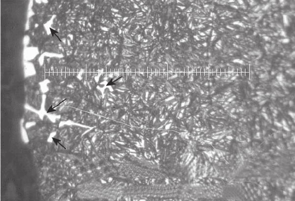
Figure 35 shows an example of bad carbur-
izing. There is a significant fraction of retained
austenite in this case-hardened part, as well as a
large, chunky, unusually shaped “puzzle piece”
carbide. This feature could be a problem for
some applications of carburized parts and may
be the result of excessive carbon potential.
Concluding Comments
For those who do failure analysis of heat
treated steel parts, it is important to understand
what microstructure is expected, given the heat
treating process that is specified. For example, in
a 1050 steel that is 100 mm in diameter and
100 mm long and water quenched, should it be
martensite? There probably will be some mar-
tensite near the surface, but it may not be a very
deep layer. The exact depth will depend on how
hot it was heated prior to quench, the details of
the quench tank design, and many other factors
that may not be readily apparent.
It is important to have a large amount of
reasonably deep knowledge to be able to make a
fair and correct determination of where there
may have been a problem in the entire process of
designing a part, procuring material, and making
a component. This knowledge base includes
failure analysis, fracture analysis, and micro-
structure analysis and interpretation in order to
“read” the process history. Simply checking the
hardness and the composition to see if they meet
the specification is not failure analysis. Failure
analysis includes a determination of the loading
geometry and background information, at the
very least, in addition to the basic certification
conformance tests.
Some people legitimately perform internal
process failure analysis on a part that never left
the door of the manufacturing plant. In failure
analysis of a field return, even from a non-end-
user assembly problem, it is important to do
more than simply look at the composition and
the hardness. The type of damage needs to be
identified, as well as the possible sources of that
Fracture #2 has both large chunky and script carbides
and large amounts of retained austenite.
01020304050
Fig. 35
“Puzzle piece” carbide microstructure in carburized steel, possibly due to excessively high carbon potential. Each small
scale division is 2 mm.
108 / Failure Analysis of Heat Treated Steel Components
Name ///sr-nova/Dclabs_wip/Failure_Analysis/5113_87-109.pdf/Chap_02b/ 21/8/2008 10:51AM Plate # 0 pg 108
type of damage. A review of the comprehen-
siveness of the design process may be in order. If
recurrence prevention is a goal of the failure
analysis, the damage specialist may lend some
understanding to the design engineers to help
them clarify the requirements of the component
characteristics.
Failure analysis can be very routine, or it can
be extremely involved. This chapter has con-
sidered only a few categories of the analysis
procedures and some of the reasoning involved
in determining what went wrong and at what part
of the life cycle the problem initiated.
A decision must be made at the beginning
of the analysis about how detailed the project
will be. If there is a single component, espe-
cially, or a very limited number of failed
parts, inadequate planning can leave inadequate
specimen material for testing in the case of
unanswered questions at the end of the project. It
is difficult to overemphasize the importance of
spending enough time initially figuring out
exactly what the goals of the failure analysis
project are and how much detail is required.
ACKNOWLEDGMENTS
The author thanks Mrs. W.T. Becker for permission
to use the copyrighted material of William T. Becker
in Fig. 6 to 8.
REFERENCE
1. D. Wulpi, Understanding How Components
Fail, American Society for Metals, 1985
Mechanisms and Causes of Failures in Heat Treated Steel Parts / 109
Name ///sr-nova/Dclabs_wip/Failure_Analysis/5113_87-109.pdf/Chap_02b/ 21/8/2008 10:51AM Plate # 0 pg 109

General Aspects of Failure Analysis
Waldek Wladimir Bose-Filho and Jose´ Ricardo Tarpani,
Universidade de Sa˜o Paulo
Marcelo Tadeu Milan, Instituto de Materiais Tecnolo´gicos do
Brasil Ltda.
FAILURE ANALYSIS is the process of
collecting, examining, and interpreting damage
evidence. The objective is to understand the
possible conditions leading to a failure and
perhaps prevent similar failures in the future.
A failure analysis should provide a well-
documented chain of evidence that either
excludes or supports possible interpretation of
the damage evidence. Clear-cut conclusions
do not always occur, and the tendency of
developing preconceived interpretations should
be avoided.
Various publications (e.g., Ref 1–6) describe
the guidelines and methods of failure analysis,
and this chapter briefly outlines some of the
basic aspects of failure analysis. The first section
describes some of the basic steps and major
concerns in conducting a failure analysis. This
is followed by a brief review of failure types
from fracture, distortion, wear, and corrosion.
Fracture is a common damage feature, because
the vast majority of mechanical failures involve
crack propagation—typically classified as duc-
tile, brittle, and fatigue, as briefly described
in more detail. Distortion, wear, and corrosion
also can be important damage factors in failure
analysis.
General Guidelines of Failure Analysis
For a complete evaluation, the sequence of
stages in the investigation and analysis of fail-
ure, as detailed in Ref 5, is as follows (Ref 2):
1. Collection of background data and selection
of samples
2. Preliminary examination of the failed part
3. Nondestructive and mechanical testing
4. Selection, identification, preservation, and/
or cleaning of specimens
5. Macroscopic examination and analysis and
photographic documentation
6. Microscopic examination and analysis
7. Selection, preparation, examination, and
analysis of metallographic specimens
8. Determination of failure mechanism
9. Chemical analysis
10. Fracture mechanics analysis
11. Testing under simulated service conditions
12. Analysis of all the evidence, formulation of
conclusions, and writing the report
These stages or steps are briefly outlined as
follows.
Collection of Background Data and
Selection of Samples. There are basically
three fundamental principles to be carefully
followed when collecting damage evidence
from a fractured material (Ref 2):
Locate the origin(s) of the fracture. The
whole fracture surface should be visually
inspected to identify the location of the
fracture-initiating site(s) and to isolate the
areas in the region of crack initiation that
will be most fruitful for further micro-
analysis. Where the size of the failed part
permits, visual examination should be con-
ducted with a low-magnification wide-field
stereomicroscope having an oblique source
of illumination (Ref 3).
Do not put the mating pieces of a fracture
back together, except with considerable care
and protection. Protection of the surfaces is
particularly important if electron micro-
scopic examination is to be part of the pro-
cedure (Ref 2). Appropriate packaging of
failed components for shipping is equally
important. Wrapping them directly into a
plastic bag, or placing pieces directly into
a plastic bottle or container, can intro-
duce unwanted hydrocarbon contaminants.
Name ///sr-nova/Dclabs_wip/Failure_Analysis/5113_111-132.pdf/Chap_03/ 18/8/2008 3:02PM Plate # 0 pg 111
Failure Analysis of Heat Treated Steel Components
L.C.F. Canale, R.A. Mesquita, and G.E. Totten, editors, p 111-132
DOI: 10.1361/faht2008p111
Copyright © 2008 ASM International®
All rights reserved.
www.asminternational.org
Fingerprints on the failed surfaces can also
introduce contamination (Ref 4);
Do not conduct a destructive testing without
considerable thought. Alterations such as
cutting, drilling, and grinding can ruin
an investigation if performed prematurely.
Destructive testing must be performed only
after all possible information has been
extracted from the part in the original con-
dition and after all significant features have
been carefully documented by photography
(Ref 2).
Preliminary Examination of the Failed
Part. In addition to locating the failure origin,
visual analysis is necessary to reveal stress con-
centrations, material imperfections, presence of
surface coatings, case-hardened regions, welds,
and other structural details that contribute to
cracking. A careful macroexamination is neces-
sary to characterize the condition of the fracture
surface so that the subsequent microexamination
strategy can be determined. Corrodents often
do not penetrate the crack tip, and this region
remains relatively clean. The visual macro-
analysis will often reveal secondary cracks that
have propagated only partially through a crac-
ked member. These part-through cracks can be
opened in the laboratory and are often in much
better condition than the main fracture (Ref 3).
Nondestructive and Mechanical Testing.
A wide variety of nondestructive testing is
available, including dye penetrant, ultrasonics,
x-ray, and eddy current, which can help in
the failure analysis task in order to unveil
even subtle and/or internal defects in a part.
Mechanical property tests are also ready to use,
ranging from a sample hardness test to elevated-
temperature tensile and impact testing. These
tests are often used to determine if degradation is
related to fabrication or to the service environ-
ment. Sometimes, a standard test can be adapted
to simulate manufacturing or in-service condi-
tions more closely (Ref 4).
Selection, Identification, Preservation,
and/or Cleaning of Specimens. Unless a
fracture is evaluated immediately after it is
produced, it should be preserved as soon as
possible to prevent attack from the environment.
The best way to preserve a fracture is to dry it
with a gentle stream of dry compressed air, then
store it in a desiccator, a vacuum storage vessel,
or a sealed plastic bag containing a desiccant.
However, such isolation of the fracture is often
not practical. Therefore, corrosion-preventive
surface coatings must be used to inhibit oxida-
tion and corrosion of the fracture surface. The
primary disadvantage of using these surface
coatings is that fracture surface debris, which
often provides clues to the cause of fracture, may
be displaced during removal of the coating.
However, it is still possible to recover the sur-
face debris from the solvent used to remove
these surface coatings by filtering the spent
solvent and capturing the residue. In regard to
cleaning techniques, fracture surfaces exposed
to various environments generally contain un-
wanted surface debris, corrosion or oxidation
products, and accumulated artifacts that must be
removed before meaningful fractography can
be performed. Before any cleaning procedures
begin, the fracture surface should be surveyed
with a low-power stereobinocular microscope,
and the results should be documented with ap-
propriate sketches or photographs. Low-power
microscope viewing will also establish the
severity of the cleaning problem and should also
be used to monitor the effectiveness of each
subsequent cleaning step. It is important to
emphasize that the debris and deposits on the
fracture surface can contain information that is
vital to understanding the cause of fracture. The
most common techniques for cleaning fracture
surfaces, in order of increasing aggressiveness,
are (Ref 3):
Dry air blast or soft organic-fiber brush
cleaning
Replica stripping
Organic-solvent cleaning
Water-based detergent cleaning
Cathodic cleaning
Chemical-etch cleaning
Macroscopic Examination and Analysis
and Photographic Documentation. More
often than not, the investigation starts with a
low-magnification, if any, observation of the
failed part. This visual examination can often
quickly answer questions such as: What was the
mode of failure? Did it crack, or was there a
uniform or pitting corrosion failure? Did the
protective oxide film break down? Were the
welds visibly contaminated? A variable magni-
fication stereoscope equipped with a ring light
and directional fiberoptic lighting is a powerful
tool for macroscopic visual examination.
Contemporary stereoscopes can operate over a
range of 2.5 to 50 · (Ref 4).
Microscopic Examination and Analysis.
Once the area of interest is isolated, a smaller
112 / Failure Analysis of Heat Treated Steel Components
Name ///sr-nova/Dclabs_wip/Failure_Analysis/5113_111-132.pdf/Chap_03/ 18/8/2008 3:03PM Plate # 0 pg 112