Canale L.C.F., Mesquita R.A., Totten G.E. Failure Analysis of Heat Treated Steel Components
Подождите немного. Документ загружается.

portion can be cut from the sample and mounted
for metallographic polishing and microscopic
examination. The microstructure of specimens
may be enhanced by a wide variety of metallo-
graphic techniques that include, for example,
heat tinting, stain etching, anodizing, and illu-
mination by bright-field and polarizing light.
Optical microscopic examination generally be-
gins at 50 · magnification and continues through
1000 · or even 1500 · . Higher levels are best
supplemented by differential interference con-
trast lighting, which allows theoretical resolu-
tion of features as fine as one-third of a
micrometer. Features that are important to
recognize include the uniformity and size of the
grain structure, the size distribution and shape of
intermetallic particles, and inclusions. Scanning
electron microscopy (SEM) is most useful
where extreme depth of focus and high magni-
fications are needed. Fractures generally are
complex, undulating surfaces that are difficult to
image, and an optical microscope can only focus
on a very narrow region because of the very
shallow depth of field. However, the SEM excels
at imaging fracture surfaces, and it can be
operated in many different modes. The most
common mode is secondary electron imaging,
which provides a detailed, high-depth-focus
image that is easy to interpret. Backscattered
“Z” contrast is used to identify regions of
impurities within a matrix. High-atomic-number
species produce a light appearance, whereas
low-atomic-number species create a darker
appearance. The topographic backscattered
mode enhances the surface topography of the
sample and accentuates height or elevation dif-
ferences on a fracture surface. The characteristic
x-rays can be detected and analyzed according to
their energy. This is called energy-dispersive
x-ray analysis. The x-ray wavelength corre-
sponds to the presence of a specific element, and
its amplitude corresponds to the quantity of
such element. This technique allows quantita-
tive characterization of elements within a given
phase. Bulk chemistry is typically analyzed
during failure analysis to verify conformance
with industry-accepted chemical limits. In the
case of reactive metals, light elements can
embrittle them due to improper processing or
service conditions (Ref 4).
Selection, Preparation, Examination, and
Analysis of Metallographic Specimens. One
of the worst things that can happen to the sample
is inadequate handling, examination, or pack-
aging. It is imperative that the sample remains in
an undisturbed state prior to analysis, because
the culprit is often found in minute surface
features or traces of impurities. Fracture surfaces
must remain untouched so that high-magnifica-
tion images can accurately determine the failure
mode. The sample must be removed carefully.
Important evidence can be destroyed by over-
heating or by allowing adjacent fracture surfaces
to fret or rub together during sectioning. The
ideal method would be to unbolt the component
or to provide adequate support so that a slow-
speed saw can be used to cut out the component.
However, sawing lubricants can mask or
destroy residual chemicals or elements on the
failed surface, so precautions become extremely
necessary. If the component has failed in the
middle of a large area, more aggressive cutting/
sectioning techniques may be warranted, but
keep a good distance from the failed region
(Ref 4).
Determination of Failure Mechanism
(with Adapted Text from Ref 7). A thorough
investigation should ensure that all damage is
found and documented, because multiple modes
and mechanisms may be present in most real-
world failure analyses. It is also important to
recognize that many unique mechanisms may be
driven by more than one environmental factor,
such as stress, temperature, corrosion, wear,
radiation, or electrical factors.
The term failure mechanism, or damage
mechanism, is meant to convey the specific
series of events that describe both how the
damage was incurred and the resulting con-
sequences. Examples of damage mechanisms
include high-temperature creep, hydrogen
embrittlement, stress-corrosion cracking, and
sulfidation. A failure or damage mechanism
describes how damage came to be present.
This definition of failure mechanism also
should not be confused with the description of
the physical characteristics of damage observed.
For example, intergranular fracture, buckling,
transgranular beach marks, and pits can all be
thought of as damage modes. The term damage
mode or failure mode is best used to describe
what damage is present.
Much confusion has occurred because of
the tendency of engineers to use the terms
mechanism and mode interchangeably; in doing
so, it is unclear that two distinct characteristics
need to be assessed. Sometimes this occurs
because, within a given system, the same
wording is used to describe both the failure
mode and mechanism. For example, pitting
General Aspects of Failure Analysis / 113
Name ///sr-nova/Dclabs_wip/Failure_Analysis/5113_111-132.pdf/Chap_03/ 18/8/2008 3:03PM Plate # 0 pg 113
describes a damage mode because the surface of
a material is pitted. In certain systems, pitting is
also a possible damage mechanism. In boiler
tubing, for example, a pitting damage mecha-
nism describes a specific localized corrosion
mechanism where pits form through dissolution
of metal either from low-pH or high-oxygen
conditions. The metal under the pit surfaces is
unaffected. In this system, pitting is a specific
damage mechanism, but many other damage
mechanisms also result in a pitting damage
mode in boiler tubing, including hydrogen
damage, phosphate corrosion, and caustic
gouging.
It is helpful to be as specific as possible in
differentiating damage mechanisms in a system.
For example, fatigue is often identified as both
a damage mode and a damage mechanism. A
fatigue damage mode is the observable damage
that occurs under fatigue loading cycles (e.g.,
the presence of beach marks). Classifying fati-
gue as a damage mechanism is not necessarily
complete because it does not point to the specific
environment that results in a fatigue damage
mode. Instead, specific mechanisms that can
result in a fatigue damage mode must be
examined. Examples include corrosion fatigue,
thermomechanical fatigue, creep-fatigue inter-
action, and mechanical fatigue.
Determination of damage mechanisms starts
by characterizing the component(s) being ex-
amined. It is impossible to know what is dif-
ferent about a failure without first understanding
what is expected from unfailed components.
In general, the analyst should obtain as much
information as possible about a part and its
background during the course of an investiga-
tion. Some key questions worth evaluating
include:
What was the part supposed to do? How was
it supposed to work?
How was the part made? What processes
were involved in its manufacture (e.g.,
forming, joining, and heat treatment)? What
properties were expected at the time of
manufacture?
What were the specified dimensions and
tolerances for the as-manufactured part?
How was the part installed?
To what service environment(s) was the part
exposed? Typical environments to examine
include operating temperatures, stresses
(steady state or slowly rising and cyclic),
oxidizing/corrosive environments, and wear
environments. What properties were re-
quired during service? How were properties
expected to change from service exposure?
How was the part inspected during service
intervals? What information was found
during these inspections?
What material characteristics were specified
for the part (e.g., composition, strength,
hardness, impact, and stress-rupture proper-
ties)? What specifications, industry stan-
dards, and contracts govern these properties?
What were the various ways the part could
fail?
The last item is a key question to repeatedly
ask throughout a failure investigation. The list of
various damage mechanisms by which a part can
fail can be narrowed down through two basic
concepts (Ref 7). Limiting conditions that refine
the scope of explanations for observed damage
can be defined by using the following two rules
of thumb:
When the impossible is eliminated, whatever
remains, however improbable, must be
considered (Sherlock Holmes rule).
When two or more explanations exist for a
sequence of events, the simple explanation is
more likely to be the correct one (Occam’s
razor).
Chemical Analysis. In a failure investiga-
tion, routine analysis of the material is usually
recommended. There are two main categories of
chemical analysis that are often used by failure
analysts:
Bulk composition evaluation: often per-
formed in order to determine whether the
correct alloy was used in the subject com-
ponent
Microchemical analysis: to find evidence of
contamination, to evaluate the composition
of microphases revealed on a metallographic
specimen, or to evaluate corrosion products
Often, chemical analysis is done last, because
an analysis usually involves destroying a certain
amount of material. There are instances where
the wrong material was used, under which con-
ditions the material may be the major cause of
failure. In many cases, however, the difficulties
are caused by factors other than material com-
position.
Extreme care must be used in interpretation of
chemical analysis work performed as part of a
failure investigation. Minor deviations from
114 / Failure Analysis of Heat Treated Steel Components
Name ///sr-nova/Dclabs_wip/Failure_Analysis/5113_111-132.pdf/Chap_03/ 18/8/2008 3:03PM Plate # 0 pg 114
specified composition must not be interpreted as
the sole cause of a failure, without much addi-
tional supporting evidence. In most instances,
slight deviations from specified compositions
are not likely to be of major importance in failure
analysis. However, small deviations in alumi-
num content can lead to strain aging in steel, and
small quantities of impurities can lead to temper
embrittlement. In specific investigations, parti-
cularly where corrosion and stress corrosion
are involved, chemical analysis of any deposit,
scale, or corrosion product, or a substance with
which the affected material has been in contact,
is required to assist in establishing the primary
cause of failure.
Where analysis shows that the content of a
particular element is slightly greater than that
required in the specifications, it should not be
inferred that such deviation is responsible for the
failure. Often, it is doubtful whether such a
deviation has played even a contributory part in
the failure. For example, sulfur and phosphorus
in structural steels are limited to 0.04% in
many specifications, but rarely can a failure in
service be attributed to sulfur content slightly in
excess of 0.04%. Within limits, the distribution
of the microstructural constituents in a material
is of more importance than their exact pro-
portions. An analysis (except a spectrographic
analysis restricted to a limited region of the
surface) is usually made on drillings represent-
ing a considerable volume of material and
therefore provides no indication of possible
local deviation due to segregation and similar
effects.
Also, certain gaseous elements, or inter-
stitials, normally not reported in a chemical
analysis, have profound effects on the mechan-
ical properties of metals. In steel, for example,
the effects of oxygen, nitrogen, and hydrogen
are of major importance. Oxygen and nitrogen
may give rise to strain aging and quench aging.
Hydrogen may induce brittleness, particularly
when absorbed during welding, cathodic clean-
ing, electroplating, or pickling. Hydrogen is
also responsible for the characteristic halos or
fisheyes on the fracture surfaces of welds in
steels, in which instance the presence of hydro-
gen often is due to the use of damp electrodes.
These halos are indications of local rupture
that has taken place under the bursting micro-
stresses induced by the molecular hydrogen,
which diffuses through the metal in the atomic
state and collects under pressure in pores and
other discontinuities. Various effects due to gas
absorption are found in other metals and alloys.
For example, excessive levels of nitrogen in
superalloys can lead to brittle nitride phases that
cause failures of highly stressed parts.
Various analytical techniques can be used
to determine elemental concentrations and to
identify compounds in alloys, bulky deposits,
and samples of environmental fluids, lubricants,
and suspensions. Semiquantitative emission
spectrography, spectrophotometry, and atomic-
absorption spectroscopy can be used to deter-
mine dissolved metals (as in analysis of an
alloy), with wet chemical methods used where
greater accuracy is needed to determine the
concentration of metals. Combustion methods
ordinarily are used for determining the con-
centration of carbon, sulfur, nitrogen, hydrogen,
and oxygen.
Wet chemical analysis methods may be
employed for determining the presence and
concentration of anions such as Cl
,NO
3
, and
S
. These methods are very sensitive.
X-ray diffraction identifies crystalline com-
pounds either on the metal surface or as a mass
of particles and can be used to analyze corrosion
products and other surface deposits. Minor and
trace elements capable of being dissolved can be
determined by atomic-absorption spectroscopy
of the solution. X-ray fluorescence spectro-
graphy can be used to analyze both crystalline
and amorphous solids, as well as liquids and
gases.
Stress Analysis and Fracture Mechanics
Analysis. When confronted with a cracked,
fractured, or deformed component, the failure
analyst will usually seek to answer some basic
questions:
Were the loads and stresses encountered by
the part at the level anticipated during
design? Or did some unexpected condi-
tion(s) contribute to the failure?
Was the material in the area of the cracking
or deformation capable of meeting the con-
ditions anticipated during design? Was there
some deficiency or discontinuity that con-
tributed to the failure, or was there a local
stress raiser at the critical location? Was this
taken into account by the designer?
In general, there are two types of conditions that
may lead to structural failure:
Net-section instability, where the overall
structural cross section can no longer sup-
port the applied load
General Aspects of Failure Analysis / 115
Name ///sr-nova/Dclabs_wip/Failure_Analysis/5113_111-132.pdf/Chap_03/ 18/8/2008 3:03PM Plate # 0 pg 115
The critical flaw size (a
c
) is exceeded
by some preexisting discontinuity or when
subcritical cracking mechanisms (for exam-
ple, fatigue, stress-corrosion cracking, or
creep) reach the critical crack size
Failures due to net-section instability typi-
cally occur when a damage process such as
corrosion or wear reduces the thickness of a
structural section. This type of failure can be
evaluated by traditional stress analysis or finite
element analysis (FEA), which are effective
methods in evaluating the effects of loading and
geometric conditions on the distribution of stress
and strain in a body or structural system.
However, stress analyses by traditional
methods or FEA do not easily account for
crack propagation from preexisting cracks or
sharp discontinuities in the material. When a
preexisting crack or discontinuity is present,
the concentration of stresses at the crack tip
becomes asymptotic (infinite) when using the
conventional theory of elasticity. In this regard,
fracture mechanics is a useful tool, because it is a
method that quantifies stresses at a crack tip
in terms of a stress-intensity parameter (K).
The fracture mechanics of cracking from a dis-
continuity or crack in a statically loaded com-
ponent has two possible situations:
The crack reaches a critical length with rapid
(brittle) separation.
The crack blunts, redistributing the stress
state, with continued loading creating a tear
zone (and sharpened crack-tip radius) in
front of the crack. In steels, this tear zone
can then cause the critical crack length to be
exceeded, such that unstable cleavage frac-
ture occurs or unstable microscale ductile
fracture is induced.
Which event occurs depends on the temperature
and the loading rate, but in either event, crack
propagation is unstable (i.e., does not require an
increasing load after creation of the tear zone).
Fracture mechanics is a tool to help evaluate the
implications of preexisting discontinuities or
cracks.
Testing under Simulated Service Con-
ditions. During the concluding stages of an
investigation, it may be necessary to conduct
tests that simulate the conditions under which
failure is believed to have occurred. Often,
simulated-service testing is not practical be-
cause elaborate equipment is required, and even
where practical it is possible that not all of the
service conditions are fully known or under-
stood. Corrosion failures, for example, are
difficult to reproduce in a laboratory, and some
attempts to reproduce them have given mis-
leading results. Serious errors can arise when
attempts are made to reduce the time required for
a test by artificially increasing the severity of one
of the factors—such as the corrosive medium or
the operating temperature. Similar problems are
encountered in wear testing.
On the other hand, when its limitations are
clearly understood, the simulated testing and
statistical experimental design analysis of the
effects of certain selected variables encountered
in service may be helpful in planning corrective
action or, at least, may extend service life. Most
of the metallurgical phenomena involved in
failures can be satisfactorily reproduced on a
laboratory scale, and the information derived
from such experiments can be helpful to the
investigator, provided the limitations of the tests
are fully recognized.
Analysis of All the Evidence, Formulation
of Conclusions, and Writing the Report.
Before starting this final step, some questions
must already be answered:
Fracture surface:
a. What is the fracture mode?
b. Is the origin of the fracture visible?
c. What is the relation between the fracture
direction and the normal or expected fra-
cture directions?
d. How many fracture origins are there?
e. Is there evidence of corrosion, paint, or
some other foreign material on the fracture
surface?
f. Was the stress unidirectional or was it
reversed in direction?
The surface of a part:
a. What is the contact pattern on the surface
of the part?
b. Has the surface of the part been deformed
by loading during service or by damage
after fracture?
c. Is there evidence of damage on the surface
of the part by manufacturing, assembling,
repairing, or service?
Geometry and design:
a. Are there any stress concentrations related
to the fracture?
b. Is the part intended to be relatively rigid,
or is it intended to be flexible, like a
spring?
c. Does the part have a basically flawless
design?
116 / Failure Analysis of Heat Treated Steel Components
Name ///sr-nova/Dclabs_wip/Failure_Analysis/5113_111-132.pdf/Chap_03/ 18/8/2008 3:03PM Plate # 0 pg 116
d. How does the part—and its assembly—
work?
e. Is the part dimensionally correct?
Manufacturing and processing:
a. Are there internal discontinuities or
stress concentrations that could cause a
problem?
b. If it is a wrought metal, does it contain
serious seams, inclusions, or forging pro-
blems, such as end grains, laps, or other
discontinuities, that could have an effect
on performance?
c. If it is a casting, does it contain shrinkage
cavities, cold shuts, gas porosity, or
other discontinuities, particularly near the
surface of the part?
d. If a weldment was involved, was the
fracture through the weld itself or through
the heat-affected zone in the parent metal
adjacent to the weld? If through the weld,
were these problems something like gas
porosity, undercutting, underbead crack-
ing, or lack of penetration? If through the
heat-affected zone adjacent to the weld,
how were the parent metal properties
affected by the heat of welding?
e. If the part was heat treated, was the treat-
ment properly performed?
Material properties:
a. Are the mechanical properties of the metal
within the specified range, if this can be
ascertained?
b. Are the properties of the metal suitable for
the application?
c. Residual and applied stress relationship.
The residual-stress system that was within
the part prior to fracture can have a pow-
erful effect—good or bad—on the perfor-
mance of a part.
d. What was the influence of adjacent parts
on the failed part?
e. Were fasteners tight?
Assembly:
a. Is there evidence of misalignment of the
assembly that could have had an effect on
the fractured part?
b. Is there evidence of inaccurate machin-
ing, forming, or accumulation of toler-
ances?
c. Did the assembly deflect excessively under
stress?
Service conditions: It is important to deter-
mine if there were any unusual occurrences,
such as strange noises, smells, fumes, or
other happenings, that could help explain the
problem. The following questions should
also be considered:
a. Is there evidence that the mechanism was
overspeeded or overloaded?
b. Is there evidence that the mechanism was
abused during service or used under con-
ditions for which it was not intended?
c. Did the mechanism or structure receive
normal maintenance with the recom-
mended materials?
d. What is the general condition of the
mechanism?
Environmental reactions: The problems
related to the environment can arise anywhere
in the history of the part: manufacturing,
shipping, storage, assembly, maintenance,
and service. None of these stages should be
overlooked in a thorough investigation that
asks:
a. What chemical reactions could have taken
place with the part during its history?
b. To what thermal conditions has the part
been subjected during its existence?
Report writing : Finally, the report analyzing
the failure should be written in a clear,
concise, logical manner. It should be clearly
structured with sections covering the fol-
lowing (Ref 6):
a. Description of the failed item
b. Conditions at the time of failure
c. Background history important to the
failure
d. Mechanical and metallurgical study of the
failure
e. Evaluation of the material quality
f. Discussion of any anomalies
g. Discussion of the mechanism or possible
mechanisms that caused the failure
h. Recommendations for the prevention of
future failures or for action to be taken with
similar pieces of equipment
Irrelevant data should be omitted, and,
depending on the nature of the problem and the
data, not every report will need full treatments
for every one of the sections listed previously.
Many times, the readership may include pur-
chasing, operating, or accounting personnel
who are not technically trained. If this is the
situation, the report should be written so that it
is comprehensible to these persons. At least,
those sections of the report that bear on their
decision-making or information needs should be
written in language that is accessible to them.
Frequently, a cover letter summarizing the most
important findings and the suggested action is a
General Aspects of Failure Analysis / 117
Name ///sr-nova/Dclabs_wip/Failure_Analysis/5113_111-132.pdf/Chap_03/ 18/8/2008 3:03PM Plate # 0 pg 117
good vehicle for reaching top executives who
are not as interested in the technical specifics but
need key findings and recommendations as a
basis for decision making. Followup on the
recommendations is frequently a difficult task
but should be undertaken for the more critical
failures. Cooperation between the investigator,
the designer, the manufacturer, and the user is
critical in developing good, workable changes.
Fracture
The process of fracture, in general terms, can
be described in terms of the mechanisms of
crack initiation and/or crack extension (growth).
Different mechanisms may occur for crack
initiation and the subsequent process of crack
growth. For example, crack extension may occur
by the brittle mechanism of cleavage, even
though extensive elongation accompanied or
preceded crack initiation. The fracture may be
classified as either ductile or brittle, depending
on whether the mechanism is describing crack
initiation or crack growth, respectively. Like-
wise, the low-energy catastrophic fracture of a
high-strength aluminum alloy by microvoid
coalescence is also difficult to classify because,
although the fracture energy is low and failure
initiates by fracture or decohesion of brittle
particles, the growth and coalescence of the
microvoids occurs by plastic deformation.
Another difficulty is that cleavage fracture may
be initiated by dislocation interactions that, by
definition, involve plasticity. This is why frac-
tures are sometimes difficult to logically classify
(Ref 5). Therefore, it is helpful to be clear
whether fracture mechanisms are describing the
process of crack initiation or extension. Crack
extension also can be multimode over time (e.g.,
fatigue crack growth followed by overload).
In terms of fracture appearances (or fracture
modes, defined earlier in the section “Deter-
mination of Failure Mechanism” in this chap-
ter), a general summary of the visual and
microscopic aspects of fracture surfaces for
metallic materials is provided in Table 1 (Ref 8).
Several analytical procedures are available for
distinguishing among the various types of frac-
ture. For example, the presence or absence of
plastic macrodeformation can be determined
with the unaided eye or by use of a steel scale, a
machinist’s micrometer, or a machinist’s or
measuring microscope. Differences in some
dimensional attribute of parts (such as width or
thickness) at and well away from the fracture can
serve to define macrodeformation after assur-
ance that both points of measurement had the
same dimension before fracture.
Fracture-surface matching is also used to
determine the presence or absence of plastic
deformation. It is very important, however, to
resist the temptation to fit the matching fracture
surfaces together, because this almost always
destroys (smears) microscopic features. The
fracture surfaces should never actually touch
during fracture-surface matching.
The origin of a fracture may be indicated by a
discoloration or by the topography of the frac-
ture surface. A discolored area on a fracture
surface may be produced by a preexisting crack
whose surfaces have been corroded or oxidized.
For example, the surfaces of a quench crack can
be oxidized during a subsequent tempering heat
treatment; the oxide film gives a bluish-black
color to the surfaces of the crack. Topographical
features that often reveal the origin of a fracture
are either chevron or river patterns or a set
of diverging ledges. If the fracture surface is
essentially featureless, the presence of a shear
lip can be used to locate, within limits, the origin
of a fracture. For example, a shear lip is not
formed at the origin of a stress-corrosion crack,
but when the crack begins to propagate rapidly, a
shear lip is formed wherever the crack front
exits from the interior to the free surface. Beach
marks, which are associated with fatigue-
initiated fractures, also provide a definite indi-
cation of the crack origin; however, it should be
noted that fracture surfaces having an appear-
ance similar to that of the beach-mark pattern
can be produced by stress corrosion.
Generally, cyclic loading produces only a
single crack, which is usually located at a site of
stress concentration or of a metallurgical defect,
whereas additional cracks, formed indepen-
dently of the main crack and at a distance from it,
may be observed on the surface of a structural
or machine component subjected to corrosion
fatigue or stress corrosion.
On the microscopic level, striations on the
fracture surface are unique to fatigue, and the
crack path, although normally transgranular, can
be intergranular. For example, intergranular
fatigue cracking can occur in the case of a car-
burized steel or in a material that has a high
density of second-phase particles at the grain
boundaries.
Corrosion-fatigue and stress-corrosion cracks
may propagate transgranularly, intergranularly,
118 / Failure Analysis of Heat Treated Steel Components
Name ///sr-nova/Dclabs_wip/Failure_Analysis/5113_111-132.pdf/Chap_03/ 18/8/2008 3:03PM Plate # 0 pg 118

Table 1 Fracture mode identification chart
Method
Instantaneous failure mode(a) Progressive failure mode(b)
Ductile overload Brittle overload Fatigue Corrosion Wear Creep
Visual, 1 to
50·
(fracture
surface)
Necking or
distortion in
direction
consistent with
applied loads
Dull, fibrous
fracture
Shear lips
Little or no
distortion
Flat fracture
Bright or coarse
texture,
crystalline,
grainy
Rays or
chevrons
point to origin
Flat progressive
zone with beach
marks
Overload zone
consistent with
applied loading
direction
Ratchet marks
where origins
join
General
wastage, rough-
ening, pitting, or
trenching
Stress-corrosion
and hydrogen
damage may
create multiple
cracks that
appear brittle
Gouging,
abrasion,
polishing,
or erosion
Galling or storing
in direction of
motion
Roughened areas
with compacted
powdered debris
(fretting)
Smooth gradual
transitions in
wastage
Multiple brittle-
appearing fissures
External surface
and internal
fissures contain
reaction scale
coatings
Fracture after
limited
dimensional
change
Scanning
electron
microscopy,
20 to
10,000·
(fracture
surface)
Microvoids
(dimples)
elongated
in direction of
loading
Single crack with
no branching
Surface slip band
emergence
Cleavage or
intergranular
fracture
Origin area may
contain an
imperfection
or stress
concentrator
Progressive
zone: worn
appearance,
flat, may show
striations at
magnification
above 500 ·
Overload zone:
may be either
ductile or brittle
Path of penetra-
tion may be
irregular,
intergranular, or
a selective phase
attacked
EDS may
help identify
corrodent(c)
Wear debris and/or
abrasive can be
characterized as to
morphology and
composition
Rolling-contact
fatigue appears
like wear in early
stages
Multiple
intergranular
fissures covered
with reaction scale
Grain faces may
show porosity
Metallographic
inspection,
50 to 1000·
(cross
section)
Grain distortion
and flow near
fracture
Irregular,
transgranular
fracture
Little distortion
evident
Intergranular or
transgranular
May relate to
notches at
surface or brittle
phases internally
Progressive
zone: usually
transgranular
with little
apparent
distortion
Overload zone:
may be either
ductile or brittle
General or
localized surface
attack (pitting,
cracking)
Selective phase
attack
Thickness and
morphology of
corrosion scales
May show
localized
distortion at
surface consistent
with direction of
motion
Identify embedded
particles
Microstructural
change typical of
overheating
Multiple inter-
granular cracks
Voids formed on
grain boundaries
or wedge-shaped
cracks at grain
triple points
Reaction scales
or internal
precipitation
Some cold flow
in last stages of
failure
Contributing
factors
Load exceeded the
strength of the part
Check for proper
alloy and proces-
sing by hardness
check or destruc-
tive testing,
chemical analysis
Loading direction
may show failure
was secondary
Short-term,
high-temperature,
high-stress rupture
has ductile
appearance
(see creep)
Load exceeded
the dynamic
strength of the
part
Check for proper
alloy and
processing as
well as proper
toughness, grain
size
Loading
direction may
show failure was
secondary or
impact induced
Low
temperatures
Cyclic stress
exceeded the
endurance limit
of the material
Check for proper
strength, surface
finish, assembly,
and operation
Prior damage by
mechanical or
corrosion modes
may have
initiated
cracking
Alignment,
vibration,
balance
High cycle low
stress: large
fatigue zone;
low cycle high
stress: small
fatigue zone
Attack morphol-
ogy and alloy
type must be
evaluated
Severity of
exposure
conditions may
be excessive;
check: pH,
temperature,
flow rate,
dissolved
oxidants, elec-
trical current,
metal coupling,
aggressive
agents
Check bulk
composition and
contaminants
For gouging or
abrasive wear:
check source of
abrasives
Evaluate effec-
tiveness of lubri-
cants
Seals or filters may
have failed
Fretting induced
by slight looseness
in clamped joints
subject to
vibration
Bearing or materi-
als engineering
design may reduce
or eliminate
problem
Water
contamination
High velocities
or uneven flow
distribution,
cavitation
Mild overheating
and/or mild
overstressing at
elevated
temperature
Unstable micro-
structures and
small grain size
increase creep
rates
Ruptures occur
after long
exposure times
Verify proper
alloy
(a) Failure at the time of load application without prior weakening. (b) Failure after a period of time where the strength has degraded due to the formation of cracks, internal
defects, or wastage. (c) EDS, energy-dispersive spectroscopy. Compiled by C.R. Morin, S.L. Meiley, and Z.B. Flanders, Packer Engineering Associates, Inc.
General Aspects of Failure Analysis / 119
Name ///sr-nova/Dclabs_wip/Failure_Analysis/5113_111-132.pdf/Chap_03/ 18/8/2008 3:03PM Plate # 0 pg 119
or by a combination of both modes. A distin-
guishing feature of stress corrosion is the
branching of the main crack. If corrosion pits
or corrosion products are found only on the
slow-growth region of a fracture surface, the
environment was in all probability sufficiently
corrosive to affect the fracture mechanism.
However, if evidence of corrosion is found on
both the slow-growth and fast-growth areas,
some corrosion took place subsequent to frac-
ture, and the environment may or may not have
influenced fracture.
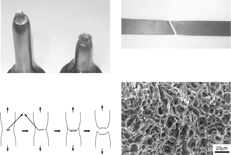
Ductile Fracture
Ductile fracture takes place when a material
capable of undergoing plastic deformation is
subjected to stresses that culminate in its rup-
ture. Macroscopically, the ductile fracture pro-
cess presents some peculiarities that allow it to
be identified immediately. The first feature is the
presence of plastic deformation that may be
accompanied by neck formation. In tensile
testpieces of ductile materials, besides necking,
the fracture surface presents a fibrous aspect and
a cup-cone geometry, as seen in Fig. 1.
The fracture process begins in the center of
the testpiece with microvoid nucleation along
grain boundaries or from interfaces such as those
found in base metal/inclusions boundaries. As
the applied stress increases, microvoids grow
and coalesce, forming a crack in the center of the
part. This process, depicted in Fig. 2, ends up in
rapid crack propagation by shearing of the
remaining ligament of the neck region, at an
angle of 45
in relation to the loading direction.
It is important to emphasize that a cup-cone
geometry will depend on the geometry and
dimensions of the part and mechanical proper-
ties of the material. Thin sheets, for instance,
present neck formation and a fracture surface
oriented at an angle of 45
in relation to the
applied load, as observed in Fig. 3. Ductile
fracture takes place intergranularly, unless some
sort of mechanism weakens the grain bound-
aries. The microscopic aspect of the fracture
surface consists of several small elliptical
cavities, or microvoids, as depicted in Fig. 4.
Brittle Fracture
Brittle fracture occurs with little or no plastic
deformation. This type of fracture is often
Fig. 1
Ductile fracture showing the typical cup-cone geo-
metry
Microvoids
Fig. 2
Schematic representation of the cup-cone geometry
formation during the ductile fracture process
Fig. 3 Thin sheet testpiece of a low-carbon steel after fracture
Fig. 4
Microvoids on the fracture surface of AA6061-T1
tensile testpiece
120 / Failure Analysis of Heat Treated Steel Components
Name ///sr-nova/Dclabs_wip/Failure_Analysis/5113_111-132.pdf/Chap_03/ 18/8/2008 3:03PM Plate # 0 pg 120
associated with materials of high strength and
low ductility or materials that were subjected
to an embrittlement process. The crack, once
nucleated, propagates very quickly in a direction
perpendicular to the applied load. Figure 5 pre-
sents an example of a gray cast iron testpiece that
presented brittle fracture.
Besides the mechanical properties, several
other factors may result in a brittle behavior,
such as temperature, loading rate, presence of
stress concentrators, and dimensions. Low tem-
peratures tend to reduce the ductility of metals,
especially those possessing a body-centered
cubic structure, resulting in a typically brittle
fracture. Figure 6 shows that as the temperature
drops, the brittle aspect on the fracture surface of
impact testpieces increases. The presence of
stress raisers or larger dimensions introduces a
more severe triaxial stress state within the
material, and thus, there is larger probability that
brittle fracture will occur. However, it is known
that the superposition of high hydrostatic stres-
ses on the material reduces the triaxiality levels,
increasing ductility. High applied loading rates
are likely to make plastic deformation more
difficult because shearing processes are time-
dependent, resulting in brittle behavior.
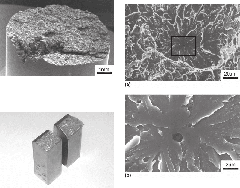
Crack propagation by brittle fracture can
occur across the grains (transgranular) or
along the grain boundaries (intergranular). In
the transgranular mode, the fracture process
takes place by cleavage along specific crystal-
lographic planes. Figure 7 presents cleavage
regions in a microalloyed low-carbon steel,
which can be identified by flat regions on the
fracture surface. Additionally, it is worth men-
tioning that most parts of steels will present
alternate regions consisting of cleavage areas
and microvoids, evidencing a mixed mode of
crack propagation.
In another situation, fracture can take place
intergranularly, because the grain boundary is a
Fig. 5
Tensile testpiece of gray cast iron presenting brittle
fracture
Fig. 6
Fracture surfaces of SAE 4140 impact testpieces.
Tested at room temperature, right, and at 196
C, left
Fig. 7
(a) Cleavage region observed in low-carbon steel.
(b) Magnification of the region delimited by the rec-
tangle in (a) showing an inclusion in the center of the cleavage
region
General Aspects of Failure Analysis / 121
Name ///sr-nova/Dclabs_wip/Failure_Analysis/5113_111-132.pdf/Chap_03/ 18/8/2008 3:03PM Plate # 0 pg 121
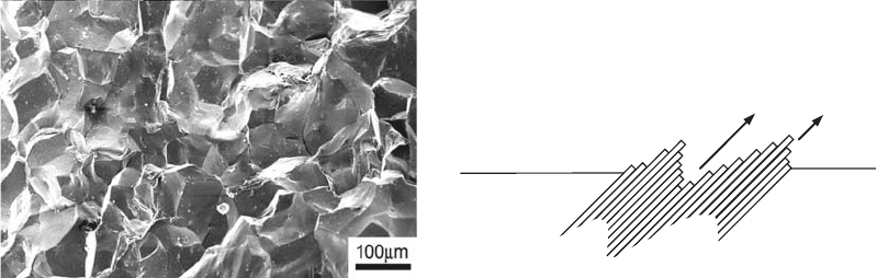
weaker path for crack propagation. Normally,
this fracture mode will occur when some
embrittlement process resulted in grain bound-
aries being more susceptible to crack propaga-
tion than the core of the grain, such as an
unsuitable heat treating or by environmental
factors. Figure 8 presents an example of inter-
granular brittle fracture in an austenitic stainless
steel SAE 316L, where grain boundaries can
clearly be observed on the fracture surface.
Fatigue Fracture
According to the definition given by ASTM
E1823, fatigue is “the process of progressive
localized permanent structural change occurring
in a material subjected to conditions that pro-
duce fluctuating stresses and strains at some
point or points and that may culminate in cracks
or complete fracture after a sufficient number of
fluctuations.” A material subjected to fatigue
can fracture at applied stresses much lower than
those necessary to fracture the same material
under monotonic conditions. The fluctuating
stresses can be originated from mechanical,
thermal, or vibration loading conditions, and the
phenomenon is responsible for more than 80%
of mechanical failures of components. For more
than 150 years, the study of metals fatigue
has involved engineers, physicists, chemists,
and mathematicians, and everyday this study
becomes more and more complex and impor-
tant. The theory about fatigue is extremely vast,
and for each question answered, another one,
more instigating, appears, requiring a broad
knowledge of materials science. In the following
topics, a brief overview is given about the main
mechanisms and factors influencing the fatigue
life of a component during both the nucleation
and crack propagation phases.
Fatigue Crack Initiation. Generally, fatigue
cracks are initiated at free surfaces, where there
is no constraint to material deformation; how-
ever, in some cases, cracks may be initiated in
the interior of the material where interfaces are
present, such as the interface of a carburized
surface layer and the base metal or the interface
of an inclusion and the base metal, or from gas
bubbles. In other cases, subsurface cracks were
found to nucleate below the surface where high
compressive residual stresses were introduced
by shot peening or surface rolling.
One of the classic models of fatigue crack
nucleation considers that when a material is
under loading (monotonic or cyclic), slips occur
at the high-shear-stress planes, creating steps on
the material surface. Under cyclic loading,
the formation of intrusions and extrusions is
observed, as schematically represented in Fig. 9.
Slip band intrusions are excellent stress raisers
that can be sites of crack nucleation.
Besides the applied stress amplitude, DS/2,
several other factors are likely to affect the
nucleation of a fatigue crack, such as the mean
stress, S
m
, or load ratio, R; geometry and surface
finishing of the part; mechanical properties; and
environment. Here, the R ratio is defined as the
ratio between the minimum and maximum loads
during the fatigue cycle.
A large proportion of fatigue data found in the
literature refers to tests conducted at S
m
= 0,
that is, for a load ratio R = 1. However, in
many engineering situations, the fluctuating
stresses are superimposed to a static stress.
Larger mean stresses reduce the nucleation time
because they facilitate the plastic deformation
mechanism associated with this phenomenon. In
an S-N graph, this can be represented by curves
shifted to the left and down, as represented in
Fig. 10.
Fig. 8
Fractograph of SAE 316L showing intergranular brittle
fracture
Metal Surface
Intrusion
Extrusion
Fig. 9
Schematic representation of an intrusion formation on
the surface of a metallic material
122 / Failure Analysis of Heat Treated Steel Components
Name ///sr-nova/Dclabs_wip/Failure_Analysis/5113_111-132.pdf/Chap_03/ 18/8/2008 3:03PM Plate # 0 pg 122