Canale L.C.F., Mesquita R.A., Totten G.E. Failure Analysis of Heat Treated Steel Components
Подождите немного. Документ загружается.

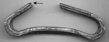
ductile fracture, or could this be a brittle frac-
ture? Imagine that only this one photograph is
available, and it must be determined whether
this was a ductile or brittle crack.
Clearly, the steel that was used to make the
link has the capability of being deformed. In
other words, the steel is ductile at the conditions
present at the time of bending. The analyst must
not be satisfied with that answer, though. The
proper analysis includes a determination of
when the deformation happened. Postfracture
deformation does not make the crack event itself
ductile. The macroscale deformation must occur
during and as an inseparable part of the fracture
process for the crack itself to be a ductile crack
event.
For those unfamiliar with this methodology,
imagining that the link broke suddenly while it
was under load can be helpful. If the crack were
ductile, one would likely see some necking at the
crack location, since chain links are generally
loaded in tension. No such localized deforma-
tion is observed in this case. On closer exam-
ination, one can see a tiny shear lip at the top
edge of the fracture surface. That makes this
crack, for the most part, a brittle crack at the
macroscale, despite the presence of available
ductility in the material. The visible deformation
near the center of the lower (originally straight)
portion of the link happened after the crack was
completely formed.
In doing fracture analysis, it is important
to distinguish the capability of ductility in the
material from the behavior at the time of
the crack event. Despite the material ductility,
the crack happened in a brittle way. Closer
examination of other views not shown provide
clear evidence that this was a fatigue crack.
Beach marks were visible. Fatigue cracks grew
below the yield strength of the component,
creating macroscale brittle features. To clarify
one other potential source of confusion, it is
important to remember that tensile refers to a
loading geometry. Fatigue is a type of crack
path. In this case, a fatigue crack grew due to a
tensile load in the horizontal portions of the link
(as shown).
To add a few more details to this case study,
the chain was in service at a plant that processes
meat, and strong acids were used to clean the
conveyor systems. This crack actually initiated
at a corrosion pit on the inside surface. The
cleaner reached the inner surfaces, but the em-
ployees may not have rinsed the chain very well.
This allowed a corrosion pit to form, which then
allowed a fatigue crack to grow. Again, it is
important to understand that the material itself is
ductile; there is nothing wrong with the material.
People involved with failure analysis need to
keep in mind that material behavior is or at
least may be different from material capability.
People doing failure analysis work need to be
able to distinguish inherent capability and actual
behavior.
To underscore the importance of separating
the behavior from the capability, imagine the
potential corrections that may be considered if
someone found this to be a ductile overload
fracture. The “cure” may be to make it harder. In
the case of the acid cleaning, harder steels are
often more susceptible to stress corrosion than
softer steels. If the “harder-is-the-answer” the-
ory were put into practice, an undesirably short
life may become a horribly short life. It is
important to be sure that a crack that is diag-
nosed as ductile is really ductile and one that is
diagnosed as brittle is really brittle. Finally,
returning to the heat treating issues, the fact that
someone misdiagnosed this crack as a ductile
fracture may lead to the heat treater being
blamed for overtempering or inadequate hard-
ening. In fact, until now, the potential blame or
innocence of the heat treater has not been
investigated in any thorough manner. It is poss-
ible that poor heat treating or poor material
manufacture contributed to the ease of corrosion
attack, and the meat processing plant employees
were blamed incorrectly. Further examination of
the microstructure is required to reveal the root
physical cause of the fracture and its timing.
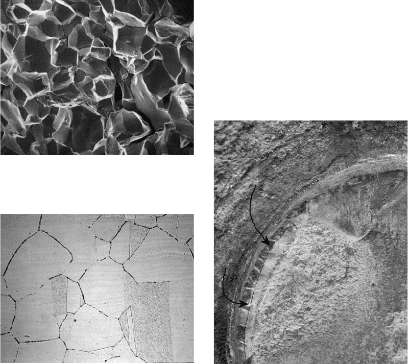
Finally, there is the shaft fragment shown in
Fig. 5. The shape is cylindrical. The image
shows one fracture face. No necking or reduc-
tion in area is visible at the fracture face location.
However, this is a ductile fracture. It is necessary
to know that this shaft broke in torsional
loading. In torsion, the shear stresses are in
the transverse orientation to the length of the
shaft. To best understand macroscale ductile and
Fig. 4
Example of a macroscale brittle fracture in tensile
loading
92 / Failure Analysis of Heat Treated Steel Components
Name ///sr-nova/Dclabs_wip/Failure_Analysis/5113_87-109.pdf/Chap_02b/ 21/8/2008 10:51AM Plate # 0 pg 92
brittle fracture, one must be familiar with normal
and shear stresses. On a simple level, normal
stresses cause macrobrittle cracks due to crack
opening forces created at the crack tip. Shear
stresses allow slip and are the basis of the
deformation that creates the ductile crack event.
So, even though there is no necking, this is a
ductile crack.
Often, it is relatively easy to see some evi-
dence of twisting on the side of a ground shaft
that has failed from ductile fracture by torsional
forces, which would lend more credibility to this
diagnosis of ductile fracture. However, this shaft
was extremely smooth, and it required a long
etching time in a heated acid solution to reveal
permanent twisting on the original cylindrical
surface.
Another possible source of confirmation that
this is a ductile crack is the classical smear
features on the fracture face. It has been argued
that these smeared features could be a result of
postfracture damage. While this is a possibility
that should be considered, since the background
evaluation revealed that the shaft was loaded in
torsion, and there are no crack opening stresses
operating on the transverse planes, this must be
a macroductile crack. A macrobrittle crack in
torsion is helical.
In closing this section on fracture, note how
important it is to follow the advice of the many
authors and teachers who state that background
research is step one of a failure analysis. The
possible loading geometries that could have
created the fracture must be reviewed to make a
proper determination of whether or not the crack
is macroscale ductile or brittle. That determina-
tion cannot be made without assessing what the
loading geometries may have been. If this frag-
ment had been totally covered with red rust, it
would have been even more difficult to deter-
mine the basic ductile or brittle behavior of the
material without knowledge of the loading
geometries and expected fragment shape.
Stress versus Strength. Almost all real
loading geometries cause the stress to be highest
somewhere along the part surface. If the strength
is uniform, for example, if there is a piece of hot
rolled 1050 steel that does not have any de-
carburization or carburization and has not been
shot peened, the crack initiation is expected
somewhere at the original part surface. In the
presence of any type of bending or torsional
stresses, the highest stress will be at the surface
of the part. In the presence of pure tensile
loading, theoretically the crack could start any-
where in the cross section. Such pure tensile
loading is rare. Imagine the case of a hydraulic
cylinder rod. Even here, there must be a section
change, a fillet, at some point. The loading at the
fillet is not uniform; there is a stress concentra-
tion. Even a tensile test coupon that is forced to
break in an area of nominally uniform strength
and stress is not totally uniformly loaded. Most
tensile test coupons are tapered so that the stress
is slightly higher at the center of the gage length.
This brings the discussion to what is so useful
about heat treating steel. Many types of steels
and heat treatments create harder or stronger
layers at the surface. Heat treating allows
the strength to be increased where it is useful.
Figure 6 is from Ref 1with annotations. This
figure shows a subsurface crack initiation along
the boundary between the induction-hardened
case and the softer core. A second initiation
appears to be inside the induction-hardened
case. It must be recalled that cracks can happen
whenever the local stress is higher than the local
strength. Normally, the stress is expected to be
highest at the surface, and the stress decreases
toward the center of the part or the center of the
cross section. In this case, the ratio of the stress
to the strength was higher below the surface than
it was at the surface, so the crack initiated sub-
surface. It is important to note such an unusual
situation, where the location of the ratio of the
stress to the strength was highest at a subsurface
position.
Fig. 5
Example of a macroscale ductile fracture in torsional
loading
Mechanisms and Causes of Failures in Heat Treated Steel Parts / 93
Name ///sr-nova/Dclabs_wip/Failure_Analysis/5113_87-109.pdf/Chap_02b/ 21/8/2008 10:51AM Plate # 0 pg 93
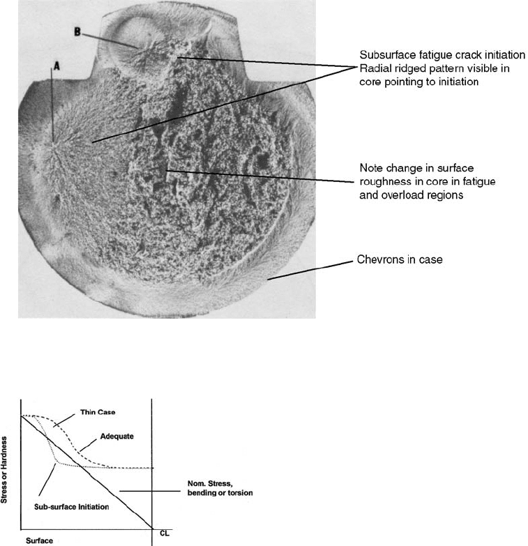
Imagine a simpler case of a cylindrical com-
ponent (Fig. 7). The surface of the part is shown
along the left side of the graph, and the center-
line is shown at right. For such a cylindrical
component that is loaded in either bending or
torsion, the stress will be highest at the
outside surface, and at the centerline, or neutral
axis, it will be nominally zero. A carburized or
induction-hardened material is actually stronger
at the surface layers where the stress is highest.
The y-axis, instead of being the stress level, can
be conceptually viewed as either the hardness or
some other measure of the strength of the com-
ponent. If the part has a heavy case, then the
strength follows the dashed line. In this case,
high strength levels go in deep toward the core.
At some point, the strength and hardness drop
off to a lower level. In this situation, if the solid
line represents the stress and the dashed line
represents the strength, this part should not have
a subsurface crack initiation. Everywhere, the
stress is lower than the strength. If the case is
too thin for the application in question, and
the strength drops off as the dotted line shows,
the stress is higher than the strength within a
subsurface band, which allows subsurface crack
initiation.
This figure shows a powerful technique for
specification of case depths, which has the
potential to complement the usual experiential
method of case depth specification. Anyone
doing fracture analysis on a case-hardened part
can also use this information to obtain an idea
about the appropriateness of the hardening spe-
cification.
It is important to realize that there is one
other case where a subsurface initiation may
occur that is not related to the heat treating or
specification quality. Imagine the presence of
a subsurface discontinuity, such as an inclusion,
a void, or a tiny crack. Even if the steel has
Fig. 7
Stress and strength as a function of position in a
cylindrical component loaded in torsion. Fracture ini-
tiation may be at either the surface or subsurface. Subsurface
initiation depends strongly on the hardness profile from surface to
center if loading is in bending or torsion.
Fig. 6
Fracture features of an induction-hardened shaft (1541 steel) after fatigue testing in rotary bending. A, B, fracture origins.
Adapted from Ref 1, with annotations by W.T. Becker
94 / Failure Analysis of Heat Treated Steel Components
Name ///sr-nova/Dclabs_wip/Failure_Analysis/5113_87-109.pdf/Chap_02b/ 21/8/2008 10:51AM Plate # 0 pg 94
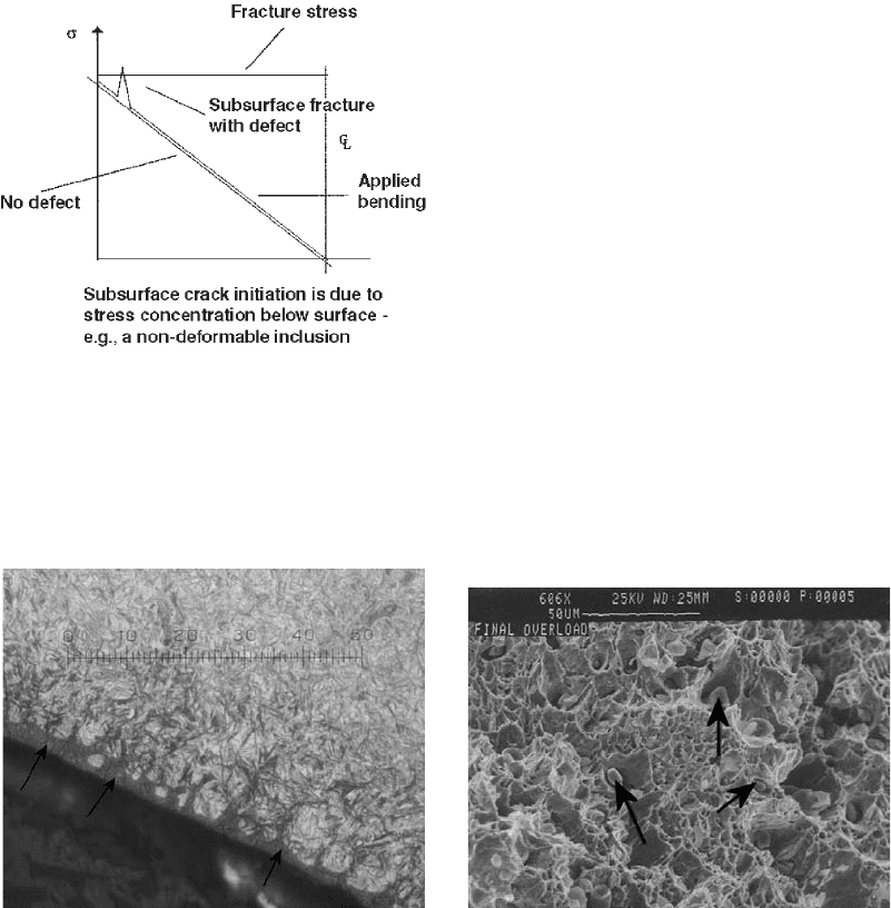
constant strength all the way through its cross
section, an inclusion that is big enough to locally
increase the stress above the fracture strength of
the part makes it possible to create a subsurface
initiation (Fig. 8).
Another potential cause of subsurface fracture
initiation is contact loading. A well-lubricated
bearing without any friction has the highest
stresses in its subsurface layers. Thus, fracture
initiation will be at a subsurface location where
contact loads are the predominant source of
stress. Inclusions can thus be very damaging in
contact-stress applications, such as bearing balls
or other rolling elements and races.
Understanding that most loading geometries
create the highest stresses at the surface also
allows one to understand why decarburized
layers can be so damaging. A decarburized layer
is softer and lower in strength than the material
with the desired nominal amount of carbon.
Decarburization can even occur on carburized
steel. Figure 9 shows a metallographic cross
section of a piece of steel that is carburized and
has quite a bit of retained austenite. Note the
dark constituent at the surface (arrows). On
carbon steels in the medium-carbon range, de-
carburization usually looks white, but here it
looks dark due to the presence of pearlite. The
decarburization affected the hardenability as
well as the hardness in this case. There was not
enough carbon to form martensite at the surface
when the part was quenched in heat treatment.
Very fine pearlite was formed instead. The
pearlite structure is not as strong or fracture
resistant as the martensite structure that is
expected in the absence of the decarburization.
Thus, this part could be more susceptible to
fracture because of the decarburization during
heat treatment.
To complete the discussion of fracture, the
previous is summarized by emphasizing that the
macroscale features reveal the loading con-
ditions. Fracture analysts must start with the
macroscale, or the big picture. Many people start
with the details, or the little picture, and move on
to the big picture, but this can be a problem that
facilitates mistakes on the part of the analyst.
Microscale Fracture Features. Scanning
electron microscopy can be used to reveal the
microscale fracture features. Figure 10 shows a
Fig. 8
Stress and strength as a function of position in a
cylindrical component loaded in torsion with subsur-
face discontinuities. Surface conditions may include: inadvertent
decarburization, typically thin and may not be easy to find; deep
case from induction or carburization; nitrided, thin case, often
not more than 5–10 mils. Part of the case may be ground off in the
finishing operations. The defect could be a faceted inclusion
(nitride) in a low-ductility matrix. Nondeformable nitride causes
stress concentration in the matrix.
Fig. 9
Decarburization of carburized steel. Each small scale
division is 2 mm.
Fig. 10
Scanning electron micrograph of microvoid coales-
cence
Mechanisms and Causes of Failures in Heat Treated Steel Parts / 95
Name ///sr-nova/Dclabs_wip/Failure_Analysis/5113_87-109.pdf/Chap_02b/ 21/8/2008 10:51AM Plate # 0 pg 95
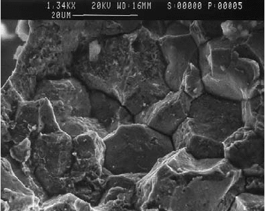
ductile crack path, or what is often called ductile
dimples, microvoids, or microvoid coalescence
(MVC). The MVC is a characteristic fracture
morphology that indicates a component was
subjected to stresses in excess of the nominal
ultimate tensile strength of the component
material.
The MVC is often an indication that the heat
treated steel did not have a gross problem with
the heat treating that caused or contributed to an
embrittlement problem. Brittle fracture features,
including cleavage and (most) intergranular
features, are often indicative of a heat treating
problem. The arrows in Fig. 10 show the non-
metallic inclusions that initiated the void for-
mation.
Brittle fractures are often unexpected and
occur suddenly without any prior warning.
Ductile fracture by MVC is typically accom-
panied by prior plastic deformation, which gives
advanced warning of the impending fracture
event. This prior warning makes MVC the pre-
ferred mechanism if fracture occurs.
While MVC is generally desirable, it can
indicate that the material is too soft if a high-
strength material is in question. The MVC can
also reveal that the heat treater made a mistake,
such as no heat treatment, despite the often
preferred MVC fracture path.
Classical microscale brittle crack paths are
along the grain boundaries (intergranular),
(Fig. 11) or cause the grains themselves to split
(transgranular or cleavage). Many heat treating
and other processing problems can cause unde-
sirable intergranular cracking at the microscale.
To have intergranular cracking, something may
either cause a low-strength condition at the grain
boundaries or cause the stresses at the grain
boundaries to be higher than in the core of the
grains. Refer to the previous concept regarding
the relationship between the local stress and the
local strength.
One mechanism where intergranular fracture
occurs is quench cracking. When a piece of steel
is quenched to harden it, martensite will gen-
erally start forming near the surface, because that
is where it cools off fastest. As anyone familiar
with heat treating of steel knows, each deeper
layer of grains will subsequently transform to
martensite. On transforming to martensite, the
material expands. As the material continues
to cool, it contracts. So, there are grains that
undergo expansion during transformation
while the grains next to them contract. Could
that create a shear stress at the grain-boundary
location? The situation is obviously more com-
plicated than just described; obviously, the grain-
boundary strength is a function of temperature,
which is rapidly changing, but it is helpful to
think about what could be causing that inter-
granular crack and why quench cracks are gen-
erally intergranular.
Note also that carburized steel often will have
intergranular cracking in fatigue. Sometimes,
even the best metallography cannot show any
problem at the grain boundaries, that is, no
grain-boundary carbides, oxides, nitrides, poro-
sity, and so on. It is true that there are many
heat treating problems that can facilitate, or be a
factor in, intergranular cracking at lower stress
levels than the part usually sustains. However, it
is important to note that just because there is an
intergranular crack, it does not mean there is
surely a heat treating problem.
Hydrogen embrittlement is often revealed in
part by its intergranular crack habit, particularly
in steels heat treated to high strength levels.
Hydrogen embrittlement is not always purely
intergranular; sometimes, there will be tiny,
shallow microvoids on the grain-boundary sur-
faces. Hydrogen embrittlement could be the heat
treater’s fault (if the hardness is too high), and it
could be an issue with the plating (if records do
not show proper baking); it could be an inter-
action between these two factors.
The important point is not to confuse identi-
fication of the crack path with the cause. There
is a difference between identification of the
physical shape of the crack and the physical
characteristics relating to the crack event. These
do not automatically lead to the cause.
Fig. 11
Scanning electron micrograph of intergranular
cracking
96 / Failure Analysis of Heat Treated Steel Components
Name ///sr-nova/Dclabs_wip/Failure_Analysis/5113_87-109.pdf/Chap_02b/ 21/8/2008 10:51AM Plate # 0 pg 96
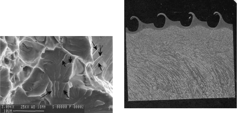
The last microscale crack path is cleavage,
and Fig. 12 shows a classical view. Ferrite
cleaves readily at low temperatures. If a part is
not supposed to have any ferrite in it and there is
a large amount of cleavage, then that may be a
clue to look carefully for ferrite during micro-
structural analysis. The classical way to recog-
nize cleavage is the presence of patterns that
look like riverbeds with multiple tributaries.
The arrows in Fig. 12 show these river line
features.
In closing this section, fatigue microscale
features in heat treated steels are often not very
interesting or classical. The experienced analyst
can recognize them, but they are difficult to
describe. They rarely have the textbook striation
features that are commonly shown for super-
alloys or aluminum alloys in published micro-
fractographs. Striations may be visible in a
low-carbon annealed steel, particularly in steels
with ferrite as part of the microstructure.
Beginners must be careful to distinguish pearlite
platelets from striations. Pearlite stops at grain
boundaries, and striations may cross grain
boundaries. If there are questions, pearlite spa-
cing can be examined on a cross section at a later
time in an effort to distinguish one from the
other. It is quite rare to find striations in any kind
of hardened steel. Beach marks are often visible
at the macroscale, but striations are very un-
common as microfractographic features.
Summarizing the differences between macro-
and microscale features: The macrofeatures
show the loading geometry. The microfeatures
show the result of the microstructural interaction
with the environment, and mechanical and che-
mical aspects may influence the way the crack
interacts with the microstructure.
Wear
The original shape of the object shown in
Fig. 13 was a gear with normal-shaped teeth. It is
severely worn. No judgments can be made about
the cause with this one image.
Wear has many similarities to fracture and
deformation. Wear is basically deformation and
fracture going on at a microscale, and it can
continue until the point that macroscale damage
is present. Scanning electron microscopy (SEM)
is very helpful in understanding how wear
happens. Wear specialists have identified many
different wear mechanisms. However, even
without that specialized knowledge, the SEM
can reveal useful information for diagnosis and
prevention. In Fig. 14, there is smeared material.
This solid steel has now flaked and smeared to
the point that it is present as thin platelets, which
are breaking off and allowing material loss. This
is one example of a combination of deformation
and fracture.
Fretting is a common type of wear that is
almost never related to heat treating or any
problem with heat treating but rather is related to
the geometry of the assembled parts. Fretting in
steel will generally produce a reddish, iron oxide
powder, and it roughens the surface. Figure 15
is an SEM image that just barely reveals
the initiation of a crack. Fretting often produces
a crack in an area that is thought to have
low stress.
Contact forces can cause surface damage due
to the action of Hertzian stresses. Figure 16
Fig. 12 Scanning electron micrograph of cleavage cracking
Fig. 13
Cross section of worn gear teeth. Approximate width
of steel segment shown is 23 mm (0.9 in.).
Mechanisms and Causes of Failures in Heat Treated Steel Parts / 97
Name ///sr-nova/Dclabs_wip/Failure_Analysis/5113_87-109.pdf/Chap_02b/ 21/8/2008 10:51AM Plate # 0 pg 97
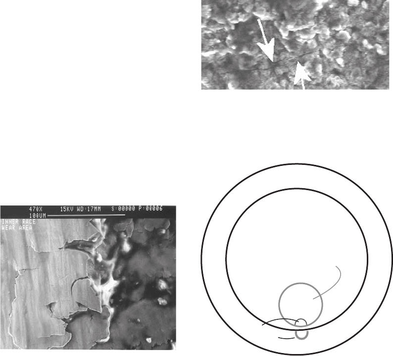
shows a bearing race and a bearing ball. The ball
is being pressed into the race. This figure is
a rough schematic, conceptually showing an
exaggerated view of the most highly stressed
area due to the elastic deformation of the two
components. Without the load, there is essen-
tially a point. Under load, the contact area
becomes circular or elliptical; in other words,
there is a contact footprint. The actual high-
stress location is just below the surface. In the
presence of friction, the highest stresses are
moved toward the surface. An important part of
bearing wear failures is determining whether the
crack initiated at the surface, showing the pos-
sibility of a lubrication issue, or if it was truly a
subsurface initiation, in which case it may be a
microstructure problem, an inclusion, or another
anomaly. Bearings are generally loaded to very
high stress levels. The quality of the steel and, in
particular, minimization of inclusions are very
important in this type of application.
Another problem is that can cause surface-
initiated cracks grinder burn, which can create
high tensile stresses at the surface. Regardless of
what the service load is, a stress field has been
created with a very high tensile stress at the
surface, the most undesirable location.
To close this section on mechanical damage,
it is often important to determine if there was a
service problem, such as abuse, or misuse, such
as using a screwdriver as a pry. Understanding
loading geometries and related fragment shapes
can shed light on this type of question.
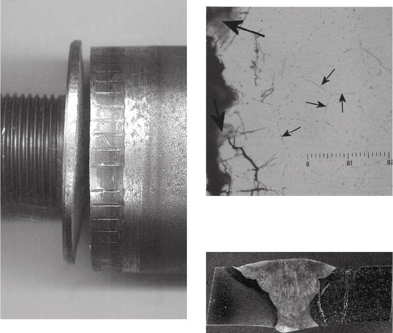
Figure 17 shows a steel bar with a threaded
portion that is much smaller in diameter than the
rest. Note that the crack is in the large-diameter
portion. Could this have been caused by
the user?
To answer the question, one would have to do
a large amount of background information col-
lection. The important point to realize is that the
crack location is totally unexpected, and it is
difficult to think of something that could have
happened in service to create a weak spot at this
hefty location.
If it cannot be qualitatively demonstrated that
somebody abused something, then it must be
quantitatively demonstrated. This is often diffi-
cult. It is important to know what the material
strength, fracture toughness, and other material
properties were at the time of the damage. It is
important to determine what the load or loading
geometry was that caused the damage. One must
Fig. 14
Scanning electron micrograph of a worn piece of
hardened medium-carbon plate showing details of
the wear mechanism
Fig. 15
Scanning electron micrograph of fatigue crack initi-
ating on worn carbonitrided steel. Original magni-
fication: approximately 4000 ·
Race
Bearing ball
Stress
concentrations
Fig. 16
Rough schematic of stresses in contact loading of a
bearing ball on a race
98 / Failure Analysis of Heat Treated Steel Components
Name ///sr-nova/Dclabs_wip/Failure_Analysis/5113_87-109.pdf/Chap_02b/ 21/8/2008 10:51AM Plate # 0 pg 98
consider how the suspected loading geometry
differs from the actual design intent. The analyst
again must remember that just because it is
broken does not mean it was abused. Even if it
meets the specification, it does not prove that the
user abused the product.
Corrosion and Environmental Damage
Figure 18 shows an example of a 300-series
stainless steel that was probably not heat treated
in the most ideal manner, since small pre-
cipitates can be seen along the grain boundaries.
Note the crack location, which seems to be
seeking the grain boundaries. To create a crack,
there must be a load or a stress. There is corro-
sion present too, so this may be a stress-
corrosion crack. Did the nonideal heat treating
condition cause the crack? In this case, a chain
of reasoning cannot directly link the specific
heat treating problem with the crack, because
there is no information about the stress
levels. Stress-corrosion cracking, by definition,
requires a threshold level of corrosion and
stress. In this case, there is no evidence that the
crack was caused by bad heat treatment. This
seemingly subtle distinction may be very
important in the case of a catastrophic failure
event.
Figure 19 shows an example that involves
another stainless steel weld. Welding is a kind
of heat treatment, although not as controlled as
an intentional heat treatment. An acid sub-
stance, polythionic acid, was in contact with
the weldment. There are some cracks on one
side of the weld, while the other side is free of
cracks. What kind of cracks are these? The
crack path is intergranular (Fig. 20). The
micrograph in Fig. 21 was taken after an
ASTM International test, and it shows ditching
Fig. 17
Steel bar with crack in unexpected position. Orig-
inally shock loaded in compression. Threaded
portion diameter is approximately 2 cm.
Fig. 18
Grain-boundary precipitates in a 300-series stainless
steel
Fig. 19 Stainless steel weldment
Mechanisms and Causes of Failures in Heat Treated Steel Parts / 99
Name ///sr-nova/Dclabs_wip/Failure_Analysis/5113_87-109.pdf/Chap_02b/ 21/8/2008 10:51AM Plate # 0 pg 99
characteristics. This indicates that whatever the
heat sequence from the weld, it did create this
condition that appears to have facilitated
intergranular corrosion. However, steel would
have been considered to pass the test for free-
dom from sensitization. Despite this, the ther-
mal experience of the material can be directly
linked to the form of the crack. Although this is
not a heat treating example, this demonstrates
the line of reasoning that is required to deter-
mine cause. It is interesting to note that one
side cracked and the other side of the weld did
not. It is likely that the side that did not crack
was an L-series, a low-carbon series, specifi-
cally made to minimize the chance of cracking
in weld heat-affected zones in stainless
steels. The cracked material was probably not
an L-series. This is an example of a classical
damage mechanism, stress-corrosion cracking.
When the regular 300-series stainless heated
up, the chromium and carbon combined and
precipitated along the grain boundaries, taking
the chromium out of solution and making the
material less corrosion resistant. Frequently,
such situations lead to pit formation, which
then allows the crack to propagate from the
stress concentration at the pit. This is an
example of a complex damage mechanism.
Another commonly named damage mech-
anism is corrosion fatigue. It must be under-
stood that a corroded part that broke due to
repeated crack extension under load did not
necessarily experience the mechanism called
corrosion fatigue. Corrosion fatigue is a dam-
age mechanism that is studied in the laboratory.
The named mechanism is invoked when it can
be demonstrated quantitatively that the crack is
growing much faster under the same loading
conditions than it would in the absence of the
corrosive substance. In a real component out in
the field, such as a heavy off-road vehicle
application, it is very difficult to obtain an
accurate service history day-by-day. Going
back to published research data for standard
test coupons and proving that a particular
situation is or is not corrosion fatigue will
likely prove very difficult. In Fig. 22, a shaft is
Fig. 21
ASTM International sensitization test results showing
ditching characteristics
Fig. 20
Scanning electron micrograph of stainless steel
weldment with intergranular cracking
Fig. 22
Cracked shaft used in a corrosive environment.
Diameter of the shaft is approximately 10 cm (4 in.).
100 / Failure Analysis of Heat Treated Steel Components
Name ///sr-nova/Dclabs_wip/Failure_Analysis/5113_87-109.pdf/Chap_02b/ 21/8/2008 10:51AM Plate # 0 pg 100
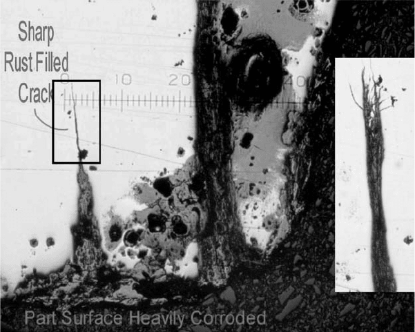
obviously corroded. The band highlighted
by the arrows was covered with a layer of red
rust. Figure 23 shows the crack created by the
corrosion and stress combination. Note that
there are also secondary cracks. The tip of this
crack looks like a witch’s broom or the trails of
a sparkler. This is not a normal fatigue crack. A
normal fatigue crack does not branch out and
have multiple tips. In this case, the corrosion
definitely has some kind of significant impact
on the damage mechanism. In many cases,
examination of field failures is likely to leave a
question mark regarding the quantitative eva-
luation of how much faster the crack is growing
because of the corrosion.
To demonstrate that corrosion is the cause
or the fault of a failure, it is not enough simply
to say the component was in a corrosive en-
vironment and it cracked because of that. It must
be assured that the specific conditions, the spe-
cific material, and the specific process condition
of the material were in the realm that has been
demonstrated to be a problem for the damage
mechanism invoked.
For example, concentration of an aggressive
substance, the threshold stress level, and the
temperature may be required to be in a restricted
range before a particular mechanism can be
properly said to have been acting.
Factors Contributing to Poor Response
from Heat Treatment
Raw Material Characteristics That
Can Contribute to Poor Response
from Heat Treatment
What are the raw material characteristics that
can contribute to poor heat treating outcome?
One very important characteristic is composi-
tion. There will be a range of values for each
type of atom that is specified for the grade in
question, as well as for unspecified elements.
A heat treater may receive material of an iron
matrix that could, with the same name, have a
very wide range of responses to the heat, heating
rate, heating dwell time, cooling rate, and so on.
Lean and rich alloy content can have a strong
influence on whether or not quench cracks occur.
Lean and rich compositions also strongly influ-
ence how readily the hardness specification is
attained. For a hardness specification that is
toward the upper limit of what can be reliably
obtained for a particular grade, it may be diffi-
cult to meet the specification for a given lot if all
the elements are on the lean end. If the part(s)
crack on quenching, an important task in the
troubleshooting process is to determine whether
it is due to a lean or rich (more likely) alloy
Fig. 23
Crack profile and adjacent secondary crack tip. Original magnification: 50 · . Inset is of a different secondary crack tip.
Original magnification: 500 ·
Mechanisms and Causes of Failures in Heat Treated Steel Parts / 101
Name ///sr-nova/Dclabs_wip/Failure_Analysis/5113_87-109.pdf/Chap_02b/ 21/8/2008 10:51AM Plate # 0 pg 101