Blum W., Riegler W., Rolandi L. Particle Detection with Drift Chambers
Подождите немного. Документ загружается.

320 9IonGates
9.2.2 Three Trigger Modes
The simplest case is the bipolar gating grid operated in a magnetic field as a diode. It
does not have to be triggered, and one avoids all switching circuitry and all pick-up
problems. There is a disadvantage to this solution: although the positive ions from
the wire avalanches are not admitted back into the drift space, all the electrons from
the drift region are allowed to produce avalanches. Under conditions where chamber
ageing is a problem, one gives away a factor of the lifetime of the chamber which
depends on the background conditions of the experiment.
The tightest trigger is the one where some counters outside the drift chamber
select the wanted event and open the gate by applying a (bipolar) voltage pulse to
the grid in order to remove the closing potential(s). Depending on the time delay T
d
between the moment of the event and the moment the gate has been opened, one
loses a length L of sensitivity given by the electron drift velocity u:
L = T
d
u .
This loss can sometimes be avoided at the expense of some background – if
there is a regular time pattern when the events occur, even if they come with low
probability. The ALEPH TPC at LEP is triggered ‘open’ a few μs before every bunch
crossing of the collider. When there is no event, the gate is switched back to ‘closed’.
In this way it is ‘open’ for 6μs out of every 22μs, but it stays ‘open’ long enough to
read an event. This mode has been termed a synchronous trigger, to be contrasted
with the asynchronous trigger described in the previous paragraph. The synchronous
trigger also avoids the disturbance on the signal lines which remains large even with
a bipolar gating grid, owing to small accidental asymmetries between neighbouring
gating-grid wires.
9.3 Transparency under Various Operating Conditions
The transmission properties of a gate can be defined with respect to the incoming
electrons. The electron transparency T
e
is the ratio between the number of electrons
traversing the grid and the number travelling towards it. In the absence of magnetic
field, T
e
is given by the corresponding ratio of the numbers of field lines. As a first
example, we have calculated T
e
in Chap. 3 for the monopolar gate as a function of
the grid potential.
Similarly the ion transparency T
i
is the fraction of ions traversing the grid, com-
pared to all the ions travelling towards it. For the synchronous trigger mode we must
also know T
i
, the time-averaged ion transparency.
In this section, computed and measured transparencies are presented for the static
and for the synchronously pulsed bipolar gate, and for the bipolar gate in a magnetic
field, operated as a diode. For the graphical representation of results and for the
comparison with measurement we use a standardized system of electrodes according
to Fig. 3.6 with wire positions as in the ALEPH TPC.
9.3 Transparency under Various Operating Conditions 321
9.3.1 Transparency of the Static Bipolar Gate
In order to describe the problem it is convenient to define two surface charge den-
sities, separating the contribution of the wires ramped at positive and negative
Δ
V
g
.
The (electron and ion) transparency is zero when the surface charge density of
positive charges is equal in absolute value to the surface charge density on the
high-voltage plane (or larger). The electric field configurations for full and for zero
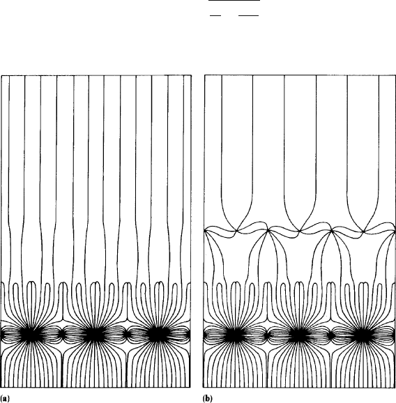
transparency are shown for our standard case in Fig. 9.3a,b.
To compute the potential difference
Δ
V
g
needed to close the gating grid we first
consider the situation in which both the high-voltage plane and the zero-grid plane
are grounded. The general solution is then obtained by superimposing the solution
calculated in Sect. 3.3 when a common voltage V
g
is applied to the wires of the
gating grid.
Using the formalism of Sect. 3.3 it can be shown that by applying
Δ
V
g
to the
wires of the gating grid we induce a positive charge on the wires at positive potential
producing a positive surface charge density
σ
+
Δ
=
−
ε
0
s
3
π
ln
π
r
g
2s
3
Δ
V
g
. (9.7)
Fig. 9.3a,b Electric field configuration in the standard case with the bipolar gating grid. (a) gate
open, (b) gate closed
322 9IonGates
The wires at negative potential contribute to a negative surface charge density
σ
−
Δ
= −
σ
+
Δ
, (9.8)
and the total charge variation on the gating grid is 0.
This solution can be superimposed on the one calculated in Sect. 3.3.1 since it
has the same boundary conditions. The total surface charge density of the wires at
potential V
g
+
Δ
V
g
is
σ
+
Δ
+
σ
g
2
, (9.9)
where
σ
g
is computed using (3.2.2).
When
σ
+
Δ
+
σ
g
/2 is positive the transparency of the gating grid is given by
T = 1 −
σ
+
Δ
+
σ
g
/2
|
σ
p
|
. (9.10)
Only half of the wires of the gating grid contribute to the positive density. This ex-
plains the factor 2 of (9.10). Formula (9.10) has been tested experimentally using
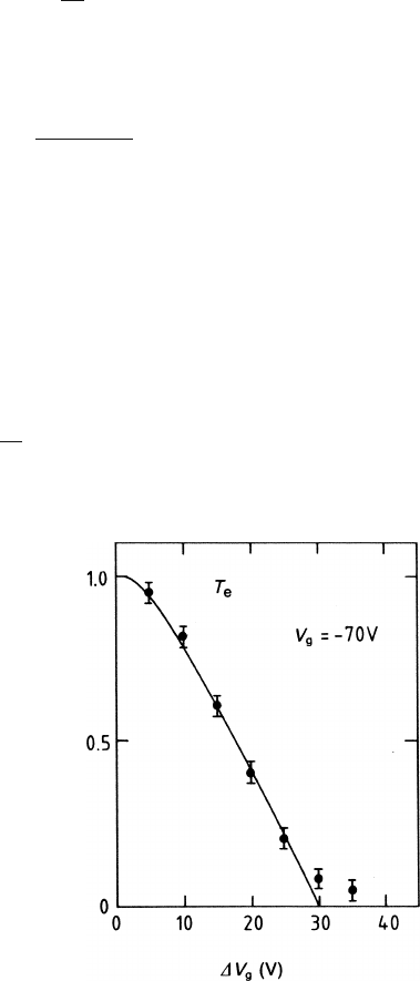
a chamber with wires arranged as shown in Fig. 3.6. We depict in Fig. 9.4a,b the
calculated and measured electron transparencies as functions of
Δ
V
g
. There is per-
fect agreement except for the large values of
Δ
V
g
where the gate was found not to
be as opaque as calculated, probably because of diffusion, which was omitted in the
calculation.
The conditions for a closed grid are
σ
+
Δ
+
σ
g
2
> |
σ
p
| =
ε
0
E , (9.11)
where E is the drift field.
Fig. 9.4a,b Electron
transparency T (here called
T
e
)ofagatinggridwith2mm
pitch, as a function of the
voltage difference
Δ
V
g
applied to adjacent wires. The
points are measurements by
[AME 85-1]; the line is a
calculation according to
(9.10)
9.3 Transparency under Various Operating Conditions 323
When
σ
g
has the limiting value for the ‘full transparency’ condition (see 3.51)
we obtain
σ
+
Δ
>
ε
0
E
1+ 2
π
r
g
s
3
. (9.12)
In the general case, using (3.53), (9.7) and (9.11) one can calculate the minimum
Δ
V
g
needed to close the grid:
Δ
V
g
> −
s
3
π
ln
π
r
g
2s
3
⎛
⎜
⎜
⎝
E −
E(z
3
−z
2
)+V
g
−V
z
2
z
3
−z
2
−
s
3
2
π
ln
2
π
r
g
s
3
⎞
⎟
⎟
⎠
. (9.13)
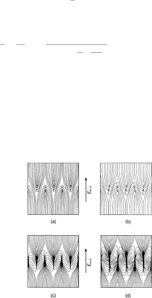
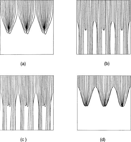
Figure 9.5a-d shows how the electric field lines are organized around the bipolar gate
as the differential voltage
Δ
V
g
is increased. We notice that for small
Δ
V
g
thegridis
partly transparent and that for larger
Δ
V
g
the field lines from the drift region end on
the wires of the gating grid. The configuration of Fig. 9.5a-db is the case where the
gate is just closed. It has field lines from the two regions in close proximity, so that
diffusion will allow a small fraction of electrons to traverse the grid. This is not the
case in Fig. 9.5a-dc and d, where the gate is more firmly closed.
9.3.2 Average Transparency of the Regularly Pulsed Bipolar Gate
The passage of a drifting electron or ion through a gate requires some time. This time
is much longer for ions than for electrons because of their smaller drift velocity u.
Fig. 9.5a-d Electric field
lines near the gating grid for
different values of
Δ
V
g
.E
drift
= 110 V/cm and
V
g
= −70 V throughout. (a)
Δ
V
g
= 30 V, (b)
Δ
V
g
= 45 V,
(c)
Δ
V
g
= 100 V, (d)
Δ
V
g
= 200 V
324 9IonGates
Fig. 9.6 Regular switching of the bipolar grid at a frequency f .
Δ
T is the ‘open’ time
Since the field region across a bipolar grid extends over some fraction of the pitch s
(see Fig. 9.5a-d) we may estimate the time to cross the gate to be roughly
τ
= s/u , (9.14)
say between 10 and 1000μs for ions and three orders of magnitude less for electrons.
A bipolar grid can be operated at a frequency f by switching the closing voltage
±
Δ
V
g
during some part of every cycle so that it is ‘open’ for the remaining time
Δ
t(
Δ
t < 1/ f ); the switching is schematized in Fig. 9.6.
If
τ
<
Δ
t, the grid can be traversed in one cycle, and the average transparency is
T∼f
Δ
t . (9.15)
When
τ
Δ
t, many cycles are needed to traverse the grid. The electric field
changes many times while the ions are near the grid, and they follow a path that
alters its direction with the variation of the electric field; see Fig. 9.7 for an illus-
tration. Each cycle, during the ‘closed’ condition, the ion makes a step towards the
gate wire at lower potential, and under favourable conditions it reaches the wire and
is absorbed.
For an accurate computation of the transparency we would have to follow the
relevant field lines at every step. But we are satisfied with an order-of-magnitude
Fig. 9.7 Sketch of the ion
path near the gating grid
pulsed at some frequency

9.3 Transparency under Various Operating Conditions 325
calculation, which will exhibit the main variables and their influence on the average
ion transparency.
We call the effective depth of the grid S – it will be some fraction of the pitch
s – and we assume that the drift field E
d
acts all the time whereas the transverse
field E
x
between the wires of the gating grid acts only during the time the gate is
closed.
Assuming that an ion needs n cycles for the traversal of the grid,
n =
Sf
v
x
, (9.16)
it is absorbed if
x
0
< n
1
f
−
Δ
t
v
x
. (9.17)
Here v
z
and v
x
are the two components of the drift velocity and x
0
is the initial
transverse distance of the ion from the closest gating wire at lower potential (see
Fig. 9.7).
The transparency is zero if
s <
S
v
z
f
1
f
−
Δ
t
v
x
, (9.18)
where s is the pitch of the gating grid.
We can calculate the transparency in the general case assuming that the ions are
uniformly distributed along x when they reach the region of the gating grid. Using
(9.16) and (9.17) we obtain
T = 1 −
S
s
v
x
v
z
(1− f
Δ
t) . (9.19)
Since the drift velocity of the ions is proportional to the electric field, the ratio
between its components can be replaced by the ratio between the components of
the electric field. The z component of the electric field is the drift field E
d
and the
x component can be approximated by 2
Δ
V
g
/s. We obtain for the time-averaged ion
transparency
T = 1 −
S
s
2
Δ
V
g
sE
d
(1− f
Δ
t) . (9.20)
Equation (9.20) shows that within the limits of our very coarse approximations, the
average transparency is a linear function of
Δ
V
g
and the frequency f.Thisisalso
borne out by experiment: in Figs. 9.8 and 9.9 we see the result of measurements
[AME 85-2] made with a gating grid operating under conditions similar to those of
the ALEPH TPC. Formula (9.20) describes both curves quite well with values of
S/s between 0.4 and 0.5.
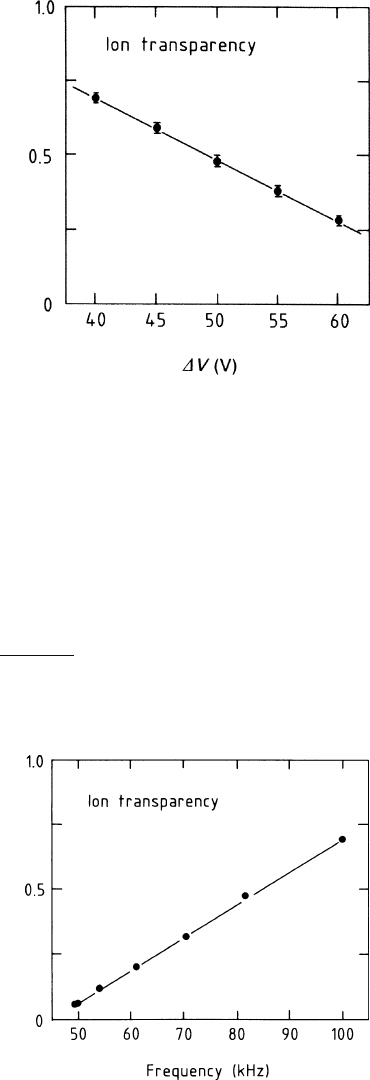
326 9IonGates
Fig. 9.8 Average
transparency T for ions
through a bipolar grid with a
pitch 2 mm, which was pulsed
at 100 kHz with an ‘open’
time of 6μs, and a ‘closed’
time of 4μs, as a function of
the voltage difference
Δ
V
applied to adjacent wires. The
points are measured by
[AME 85-2]; the straight line
was drawn to connect the
points
9.3.3 Transparency of the Static Bipolar Gate in a Transverse
Magnetic Field
A magnetic field along the main drift direction z changes the path of the electrons
according to the parameter
ωτ
; see (2.6). The components u
x
of the drift velocity
perpendicular to the magnetic field and perpendicular to the grid wires is reduced
by the factor 1 +
ω
2
τ
2
, whereas the drift velocity u
z
in the main direction stays the
same:
u
x
=
1
1+
ω
2
τ
2
μ
E
x
,
u
z
= μE
z
.
(9.21)
Fig. 9.9 Average
transparency T for ions
through a bipolar grid (pitch
2 mm), which was pulsed
with
Δ
V
g
= ±45 V for a
constant ‘open’ time of 6μs,
as a function of the frequency.
The points are measured by
[AME 85-2]; the straight line
was drawn to connect the
points
9.3 Transparency under Various Operating Conditions 327
Here
μ
is the electron mobility. We see that there is a strong influence of the mag-
netic field on the operation of the bipolar gate – it is closed at much higher values
of
Δ
V
g
, since the relevant drift-velocity component u
x
, which moves the electrons
towards the wires of the grid, is reduced.
We can construct the drift trajectories when we know the behaviour of
ωτ
with
the electric field strength E. This could be calculated according to the principles
discussed in Sect. 2.2.3. But for our example we simply use
ωτ
= 6(T
−1
)B for E < 100V/cm ,
ωτ
= 6(T
−1
)B100(V/cm)/E for E > 100V/cm .
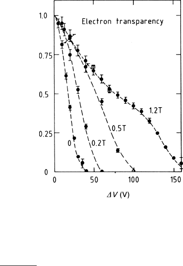
Figure 9.10a-d shows the electron drift lines in the x–z plane for a number of
conditions. The electron transparency is computed counting the fraction of drift ve-
locity lines that cross the grid. Comparing Figs. 9.10a-da and b, one observes that
the magnetic field of 1.5 T changed the transparency from zero to about 80%.
Figure 9.11 displays the measured electron transparency of a gating grid with a
pitch of 2 mm in a drift field of 100 V/cm for different values of the magnetic field
[AME 85-1]. One observes that the closing voltage goes up roughly linearly with
the magnetic field.
Displacement of the Electrons along the Wire Direction. The electrons cross the
gating grid in the presence of a component (x) of the electric field perpendicular
to the magnetic field. Owing to the E ×B term of the drift-velocity equation (2.6)
Fig. 9.10a-d Electron
trajectories approaching the
grid from the drift region.
E = 110 V/cm. (a)
Δ
V
g
= 45 V, B = 0, (b)
Δ
V
g
= 45 V, B = 1.5T,(c)
Δ
V
g
= 70 V, B = 1.5T,(d)
Δ
V
g
= 200 V, B = 1.5T
328 9IonGates
Fig. 9.11 Electron
transparency vs.
Δ
V
g
(here
called
Δ
V) for various
magnetic fields, as measured
by [AME 85-1]. The lines are
drawn to guide the eye. The
two squares show the result of
calculations according to
Sect. 9.3.3
they are also displaced along the direction (y) parallel to the wires of the grid. The
component of the drift velocity along the wire direction is
u
y
=
ωτ
1+
ω
2
τ
2
μ
E
x
.
This effect is similar to the displacement of the electrons along the sense-
wire direction when they approach the sense wire from the zero-grid region (see
Sect. 7.3.1).
Figure 9.5a-db shows the electric field lines in the region of the gating grid when
the grid is closed for the ions (but not for the electrons if a strong magnetic field is
present). The electric field is roughly constant between two sides of the grid, and its
x component changes sign on the two sides of the same wire. All the electrons that
cross the grid on the same side of a given wire are displaced along y in the same
direction and roughly by the same amount; all the others that pass on the other side
are displaced by the same amount but in the opposite direction. This displacement
can be of the order of fractions of a millimetre and depends on
Δ
V
g
, on the magnetic
field and on the gas mixture.
The distribution of the arrival point of the electrons on the sense wire is modified.
This effect influences the spatial resolution in a similar way as the E ×B effect at
the sense wire.
If the pitch of the gating grid and the sense-field grid are the same, it is pos-
sible to choose the sign of
Δ
V
g
in such a way that the y displacement at the
gating grid has sign opposite to the y displacement at the sense wire [AME 86].
In this case there is a compensation of the overall E × B effect with a pos-
sible benefit to the spatial resolution; nothing quantitative has appeared in the
literature.
References 329
References
[AME 85-1] S.R. Amendolia et al., Influence of the magnetic field on the gating of a time
projection chamber, Nucl. Instrum. Methods Phys. Res. A 234, 47 (1985)
[AME 85-2] S.R. Amendolia et al., Ion trapping properties of a synchronously gated time pro-
jection chamber, Nucl. Instrum. Methods Phys. Res. A 239, 192 (1985)
[AME 86] S.R. Amendolia et al., Gating in the ALEPH time projection chamber, Nucl. In-
strum. Methods Phys. Res. A 252, 403 (1986) and CERN-EF preprint 84–11 (1984)
(unpublished)
[BEI 88] S.P. Beingessner, T.C. Meyer, M. Yvert, Influence of chemical trace additives on
the future ageing of the UA1 Central detector. Nucl. Instrum. Methods Phys. Res.
A 272, 669 (1988)
[BRE 80] A. Breskin, G. Charpak, S. Majewski, G. Melchart, A. Peisert, F. Sauli, F. Mathy,
G. Petersen, High flux operation of the gated multistep avalanche chamber, Nucl.
Instrum. Methods 178, 11 (1980)
[BRY 85] D.A. Bryman et al., Gated grid system used with a time projection chamber, Nucl.
Instrum. Methods Phys. Res. A 234, 42 (1985)
[KEN 84] Joel Kent, Positive ion suppression with untriggered TPC; College de France
Preprint 84–17 (1984) (unpublished)
[NEM 83] P. Nemethy, P.J. Oddone, N. Toge, A. Ishibashi, Gated time projection chamber,
Nucl. Instrum. Methods Phys. Res. 212, 273 (1983)