Blum W., Riegler W., Rolandi L. Particle Detection with Drift Chambers
Подождите немного. Документ загружается.

Contents xi
4 Amplification of Ionization ......................................125
4.1 The Proportional Wire . . . . ..................................125
4.2 Beyond the Proportional Mode . . . . ...........................128
4.3 Lateral Extent of the Avalanche . . . . ...........................130
4.4 Amplification Factor (Gain) of the Proportional Wire . ............132
4.4.1 TheDiethornFormula................................134
4.4.2 Dependence of the Gain on the Gas Density . . ............136
4.4.3 Measurement of the Gain Variation with Sense-Wire
VoltageandGasPressure .............................136
4.5 Local Variations of the Gain..................................138
4.5.1 VariationoftheGainNeartheEdgeoftheChamber.......138
4.5.2 Local Variation of the Gain Owing to Mechanical
Imperfections .......................................139
4.5.3 Gain Drop due to Space Charge . .......................142
4.6 StatisticalFluctuationoftheGain.............................145
4.6.1 Distributions of Avalanches in Weak Fields . . ............145
4.6.2 Distributions of Avalanches in Electronegative Gases . .....147
4.6.3 Distributions of Avalanches in Strong Homogeneous Fields . 149
4.6.4 Distributions of Avalanches in Strong Non-uniform Fields . . 151
4.6.5 The Effect of Avalanche Fluctuations on the Wire
PulseHeights .......................................151
4.6.6 A Measurement of Avalanche Fluctuations
Using Laser Tracks...................................152
References . ....................................................154
5 Creation of the Signal ..........................................157
5.1 The Principle of Signal Induction by Moving Charges ............157
5.2 Capacitance Matrix, Reciprocity Theorem . . . . . . ................158
5.3 Signals Induced on Grounded Electrodes, Ramo’s Theorem . . .....160
5.4 Total Induced Charge and Sum of Induced Signals . . . ............161
5.5 Induced Signals in a Drift Tube . . . . ...........................163
5.6 Signals Induced on Electrodes Connected with Impedance Elements 165
5.6.1 ApplicationtoaDriftTubeanditsCircuitry..............169
5.6.2 Alternative Methods for the Calculation of the Signal . .....171
5.7 Signals Induced in Multiwire Chambers . .......................172
5.7.1 Signals Induced on Wires . . ...........................172
5.7.2 Signals Induced on Cathode Strips and Pads . . ............176
References . ....................................................179
6 Electronics for Drift Chambers ..................................181
6.1 Linear Signal Processing . . ..................................183
6.1.1 LaplaceandFourierTransforms........................183
6.1.2 Transfer Functions, Poles and Zeros, Delta Response . .....185
6.1.3 CR, RC, Pole-zero and Zero-pole Filters . ................187
6.1.4 Cascading of Circuit Elements . . .......................191
xii Contents
6.1.5 Amplifier Types, Bandwidth, Sensitivity, and Ballistic
Deficit .............................................192
6.2 Signal Shaping . . . . .........................................194
6.2.1 Unipolar and Bipolar Signal Shaping . . . . ................195
6.2.2 Signal Tail Cancellation . . . . ...........................200
6.2.3 Signal Pileup, Baseline Shift, and Baseline Fluctuations . . . . 205
6.2.4 Input Circuit . . . . . . ..................................211
6.3 Noise and Optimum Filters ..................................213
6.3.1 NoiseCharacterization................................214
6.3.2 Noise Sources . . . . . ..................................217
6.3.3 NoiseinWireChambers ..............................225
6.3.4 A Universal Limit on the Signal-to-Noise Ratio . . . . . . .....231
6.4 ElectronicsforChargeMeasurement ..........................234
6.5 ElectronicsforTimeMeasurement ............................235
6.5.1 Influence of Electronics Noise on Time Resolution . . . .....237
6.5.2 Influence of Pulse-Height Fluctuations on Time Resolution . 239
6.5.3 Influence of Electron Arrival Time Fluctuations
onTimeResolution ..................................241
6.6 Three Examples of Modern Drift Chamber Electronics . . . . . . .....246
6.6.1 TheASDBLRFront-endElectronics....................246
6.6.2 TheATLASCSCFront-endElectronics .................247
6.6.3 The PASA and ALTRO Electronics for the ALICE TPC . . . . 247
References . ....................................................248
7 Coordinate Measurement and Fundamental Limits of Accuracy .....251
7.1 Methods of Coordinate Measurement . . . .......................251
7.2 BasicFormulaeforaSingleWire .............................253
7.2.1 Frequency Distribution of the Coordinates of a Single
Electron at the Entrance to the Wire Region . . ............254
7.2.2 Frequency Distribution of the Arrival Time of a Single
Electron at the Entrance to the Wire Region . . ............256
7.2.3 Influence of the Cluster Fluctuations on the Resolution –
theEffectiveNumberofElectrons......................257
7.3 Accuracy in the Measurement of the Coordinate in or near the Wire
Direction..................................................261
7.3.1 Inclusion of a Magnetic Field Perpendicular to the Wire
Direction: the Wire E ×
×
× B Effect.......................261
7.3.2 Case Study of the Explicit Dependence of the Resolution
on L and θ ..........................................263
7.3.3 The General Situation – Contributions of Several Wires,
and the Angular Pad Effect . ...........................264
7.3.4 Consequences of (7.33) for the Construction of TPCs . .....268
7.3.5 A Measurement of the Angular Variation of the Accuracy . . 268
7.4 Accuracy in the Measurement of the Coordinate
intheDriftDirection........................................270
Contents xiii
7.4.1 Inclusion of a Magnetic Field Parallel to the Wire
Direction: the Drift E×B Effect .......................271
7.4.2 AverageArrivalTimeofManyElectrons ................272
7.4.3 Arrival Time of the MthElectron.......................272
7.4.4 Variance of the Arrival Time of the Mth Electron:
ContributionoftheDrift-PathVariations.................273
7.4.5 Variance of the Arrival Time of the Mth Electron:
ContributionoftheDiffusion ..........................275
7.5 Accuracy Limitation Owing to Wire Vibrations . ................277
7.5.1 Linear Harmonic Oscillator Driven by Random Pulses .....278
7.5.2 Wire Excited by Avalanche Ions ........................279
7.6 Accuracy Limitation Owing to Space Charge Fluctuations . . . .....281
References . ....................................................288
8 Geometrical Track Parameters and Their Errors ..................291
8.1 Linear Fit . . . . .............................................292
8.1.1 Case of Equal Spacing Between x
0
and x
N
...............293
8.2 Quadratic Fit . .............................................294
8.2.1 ErrorCalculation ....................................295
8.2.2 Origin at the Centre of the Track – Uniform
Spacing of Wires . . ..................................296
8.2.3 Sagitta .............................................298
8.2.4 Covariance Matrix at an Arbitrary Point Along
theTrack ...........................................299
8.2.5 Comparison Between the Linear and Quadratic Fits
in Special Cases . . . ..................................300
8.2.6 Optimal Spacing of Wires . . ...........................302
8.3 A Chamber and One Additional Measuring Point Outside .........302
8.3.1 Comparison of the Accuracy in the Curvature Measurement 304
8.3.2 Extrapolation to a Vertex . . . ...........................304
8.4 Limitations Due to Multiple Scattering . . .......................306
8.4.1 BasicFormulae......................................306
8.4.2 VertexDetermination.................................309
8.4.3 Resolution of Curvature for Tracks Through
aScatteringMedium .................................310
8.5 Spectrometer Resolution. . . ..................................311
8.5.1 LimitofMeasurementErrors ..........................311
8.5.2 Limit of Multiple Scattering ...........................312
References . ....................................................313
9IonGates.....................................................315
9.1 ReasonsfortheUseofIonGates..............................315
9.1.1 ElectricChargeintheDriftRegion .....................315
9.1.2 Ageing.............................................318
9.2 Survey of Field Configurations and Trigger Modes . . . ............318
xiv Contents
9.2.1 Three Field Configurations . ...........................318
9.2.2 Three Trigger Modes . . . . . . ...........................320
9.3 Transparency under Various Operating Conditions . . . ............320
9.3.1 TransparencyoftheStaticBipolarGate .................321
9.3.2 Average Transparency
oftheRegularlyPulsedBipolarGate....................323
9.3.3 Transparency of the Static Bipolar Gate in a Transverse
Magnetic Field . . . . ..................................326
References . ....................................................329
10 Particle Identification by Measurement of Ionization ...............331
10.1 Principles .................................................331
10.2 Shape of the Ionization Curve . . . . . ...........................334
10.3 Statistical Treatment of the n Ionization Samples
ofOneTrack ..............................................337
10.4 Accuracy of the Ionization Measurement . . . . . . . ................339
10.4.1 Variation with n and x ................................339
10.4.2 VariationwiththeParticleVelocity .....................340
10.4.3 VariationwiththeGas ................................341
10.5 Particle Separation .........................................344
10.6 ClusterCounting...........................................345
10.7 IonizationMeasurementinPractice ...........................347
10.7.1 Track-Independent Corrections . . .......................347
10.7.2 Track-Dependent Corrections . . . .......................348
10.8 Performance Achieved in Existing Detectors ....................349
10.8.1 Wire Chambers Specialized to Measure Track Ionization . . . 349
10.8.2 IonizationMeasurementinUniversalDetectors...........354
References . ....................................................358
11 Existing Drift Chambers – An Overview ..........................361
11.1 Definition of Three Geometrical Types of Drift Chambers . . . . .....361
11.2 HistoricalDriftChambers ...................................362
11.3 Drift Chambers for Fixed-Target and Collider Experiments . .....365
11.3.1 General Considerations Concerning the Directions of
Wires and Magnetic Fields . ...........................366
11.3.2 TheDilemmaoftheLorentzAngle .....................367
11.3.3 Left–RightAmbiguity ................................368
11.4 Planar Drift Chambers of Type 1 . . . ...........................368
11.4.1 CoordinateMeasurementintheWireDirection ...........368
11.4.2 FiveRepresentativeChambers .........................369
11.4.3 Type 1 Chambers without Field-Shaping Electrodes . . .....375
11.5 LargeCylindricalDriftChambersofType2 ....................377
11.5.1 Coordinate Measurement along the Axis – Stereo Chambers 377
11.5.2 Five Representative Chambers
with(Approximately)AxialWires......................377
Contents xv
11.5.3 DriftCells ..........................................380
11.5.4 TheUA1CentralDriftChamber .......................384
11.5.5 TheATLASMuonDriftChambers(MDT)...............385
11.5.6 A Large TPC System for High Track Densities . . . . . . .....388
11.6 Small Cylindrical Drift Chambers of Type 2
forColliders(VertexChambers) ..............................390
11.6.1 SixRepresentativeChambers ..........................393
11.7 DriftChambersofType3....................................397
11.7.1 Double-Track Resolution in TPCs . . . . . . ................398
11.7.2 FiveRepresentativeTPCs .............................399
11.7.3 AType3ChamberwithaRadialDriftField..............403
11.7.4 A TPC for Heavy-Ion Experiments . . . . . ................404
11.7.5 AType3ChamberasExternalParticleIdentifier..........404
11.7.6 A TPC for Muon-Decay Measurements . . ................406
11.8 Chambers with Extreme Accuracy . ...........................407
References . ....................................................409
12 Drift-Chamber Gases ...........................................413
12.1 General Considerations Concerning the Choice of Drift-
ChamberGases ............................................413
12.2 InflammableGasMixtures...................................416
12.3 Gas Purity, and Some Practical Measurements
of Electron Attachment . . . . ..................................420
12.3.1 Three-Body Attachment to O
2
, Mediated
by CH
4
,i-C
4
H
10
and H
2
O.............................420
12.3.2 ‘Poisoning’ of the Gas by Construction Materials, Causing
Electron Attachment . . . . . . ...........................422
12.3.3 The Effect of Minor H
2
O Contamination
ontheDriftVelocity..................................422
12.4 Chemical Compounds Used for Laser Ionization ................424
12.5 ChoiceoftheGasPressure...................................426
12.5.1 Point-Measuring Accuracy . ...........................427
12.5.2 LorentzAngle.......................................428
12.5.3 Drift-Field Distortions from Space Charge . . . ............429
12.6 Deterioration of Chamber Performance
withUsage(‘Ageing’) ......................................429
12.6.1 General Observations in Particle Experiments ............430
12.6.2 DarkCurrents.......................................430
12.6.3 AgeingTestsintheLower-FluxRegime.................433
12.6.4 AgeingTestsintheHigh-FluxRegime ..................435
References . ....................................................439
Index .............................................................443

Chapter 1
Gas Ionization by Charged Particles
and by Laser Rays
Charged particles can be detected in drift chambers because they ionize the gas
along their flight path. The energy required for them to do this is taken from their
kinetic energy and is very small, typically a few keV per centimetre of gas in normal
conditions.
The ionization electrons of every track segment are drifted through the gas and
amplified at the wires in avalanches. Electrical signals that contain information
about the original location and ionization density of the segment are recorded.
Our first task is to review how much ionization is created by a charged particle
(Sects. 1.1 and 1.2). This will be done using the method of Allison and Cobb, but
the historic method of Bethe and Bloch with the Sternheimer corrections is also
discussed. Special emphasis is given to the fluctuation phenomena of ionization.
Pulsed UV lasers are sometimes used for the creation of straight ionization tracks
in the gas of a drift chamber. Here the ionization mechanism is quite different from
the one that is at work with charged particles, and we present an account of the
two-photon rate equations as well as of some of the practical problems encountered
when working with laser tracks (Sect. 1.3).
1.1 Gas Ionization by Fast Charged Particles
1.1.1 Ionizing Collisions
A charged particle that traverses the gas of a drift chamber leaves a track of ioniza-
tion along its trajectory. The encounters with the gas atoms are purely random and
are characterized by a mean free flight path λ between ionizing encounters given by
the ionization cross-section per electron
σ
I
and the density N of electrons:
λ = 1/(N
σ
I
). (1.1)
Therefore, the number of encounters along any length L has a mean of L/λ, and the
frequency distribution is the Poisson distribution
W. Blum et al., Particle Detection with Drift Chambers,1
doi: 10.1007/978-3-540-76684-1
1,
c
Springer-Verlag Berlin Heidelberg 2008

2 1 Gas Ionization by Charged Particles and by Laser Rays
P(L/λ,k)=
(L/λ)
k
k!
exp(−L/λ). (1.2)
It follows that the probability distribution f (l)dl of the free flight paths l between
encounters is an exponential, because the probability of finding zero encounters in
the interval l times the probability of one encounter in dl is equal to
f (l)dl = P(1/λ,0)P(dl/λ,1)
=(1/λ)exp(−l/λ)dl.
From (1.2) we obtain the probability of having zero encounters along a track
length L:
P(L/λ,0)=exp(−L/λ). (1.3)
Equation (1.3) provides a method for measuring λ. If a gas counter with sensitive
length L is set up so that the presence of even a single electron in L will always give a
signal, then its inefficiency may be identified with expression (1.3), thus measuring
λ. This method has been used with streamer, spark, and cloud chambers, as well as
with proportional counters and Geiger–M
¨
uller tubes. A correction must be applied
when a known fraction of single electrons remains below the threshold.
Table 1.1 shows a collection of measured values of 1/λ with fast particles whose
relativistic velocity factor
γ
is quoted as well, because λ depends on the particle
velocity (see Sect. 1.2.6); in fact, 1/λ goes through a minimum near
γ
= 4.
Table 1.1 Measured numbers of ionizing collisions per centimetre of track length in various gases
at normal density [ERM 69]. The relativistic velocity factor
γ
is also indicated
Gas 1cm/λ
γ
H
2
5.32±0.06 4.0
4.55±0.35 3.2
5.1±0.83.2
He 5.02±0.06 4.0
3.83±0.11 3.4
3.5±0.2
a
3.6
Ne 12.4±0.13 4.0
11.6±0.3
a
3.6
Ar 27.8±0.34.0
28.6±0.53.5
26.4±1.83.5
Xe 44 4.0
N
2
19.3 4.9
O
2
22.2±2.34.3
Air 25.4 9.4
18.5±1.33.5
a
[S
¨
OC 79].

1.1 Gas Ionization by Fast Charged Particles 3
Table 1.2 Minimal primary ionization cross-sections
σ
p
for charged particles in some gases, and
relativistic velocity factor
γ
min
of the minimum, according to measurements done by Rieke and
Prepejchal [RIE 72]
Gas
σ
p
(10
−20
cm
2
)
γ
min
Gas
σ
p
(10
−20
cm
2
)
γ
min
H
2
18.7 3.81 i-C
4
H
10
333 3.56
He 18.6 3.68 n-C
5
H
12
434 3.56
Ne 43.3 3.39 neo-C
5
H
12
433 3.45
Ar 90.3 3.39 n-C
6
H
14
526 3.51
Xe 172 3.39 C
2
H
2
126 3.60
O
2
92.1 3.43 C
2
H
4
161 3.58
CO
2
132 3.51 CH
3
OH 155 3.65
C
2
H
6
161 3.58 C
2
H
5
OH 230 3.51
C
3
H
8
269 3.47 (CH
3
)
2
CO 277 3.54
In Table 1.2 we present additional measurements of a larger number of gases
that are employed in drift chambers. These primary ionization cross-sections
σ
p
were measured by Rieke and Prepejchal [RIE 72] in the vicinity of the minimum
at different values of
γ
and interpolated to the minimum
γ
min
p
at
γ
min
,usingthe
parametrization of the Bethe–Bloch formula (see Sect. 1.2.7). The mean free path λ
is related to
σ
p
by the number density N
m
of molecules:
λ = 1/(N
m
σ
p
).
The measurement errors are within ±4% (see the original paper for details). In
comparison with the values presented in Table 1.1, the measurements are in rough
agreement, except for argon.
1.1.2 Different Ionization Mechanisms
We distinguish between primary and secondary ionization. In primary ionization,
one or sometimes two or three electrons are ejected from the atom A encountered
by the fast particle, say a
π
meson:
π
A →
π
A
+
e
−
,
π
A
++
e
−
e
−
,... (1.4)
Most of the charge along a track is from secondary ionization where the electrons
are ejected from atoms not encountered by the fast particle. This happens either in
collisions of ionization electrons with atoms,
e
−
A → e
−
A
+
e
−
, e
−
A
++
e
−
e
−
, (1.5)
or through intermediate excited states A
∗
. An example is the following chain of
reactions involving the collision of the excited state with a second species, B, of
atoms or molecules that is present in the gas:
π
A →
π
A
∗
(1.6a)

4 1 Gas Ionization by Charged Particles and by Laser Rays
or
e
−
A → e
−
A
∗
, (1.6b)
A
∗
B → AB
+
e
−
. (1.7)
Reaction (1.7) occurs if the excitation energy of A
∗
is above the ionization potential
of B. In drift chambers, A
∗
is often the metastable state of a noble gas created in
reaction (1.6b), and B is one of the molecular additives (quenchers) that are required
for the stability of proportional wire operation; A
∗
may also be an optical excitation
with a long lifetime due to resonance trapping. These effects are known under the
names of Penning effect (involving metastables) and Jesse effect (involving optical
excitations, also used more generally); obviously they depend very strongly on the
gas composition and density.
Another example of secondary ionization through intermediate excitation has
been observed in pure rare gases where an excited molecule A
∗
2
has a stable ionized
ground state A
+
2
:
A
∗
A → A
∗
2
→ A
+
2
e
−
. (1.8)
The different contributions of processes (1.5–1.8) are in most cases unknown. For
further references, we recommend the proceedings of the conferences dedicated to
these phenomena, for example the Symposium on the Jesse Effect and Related Phe-
nomena [PRO 74].
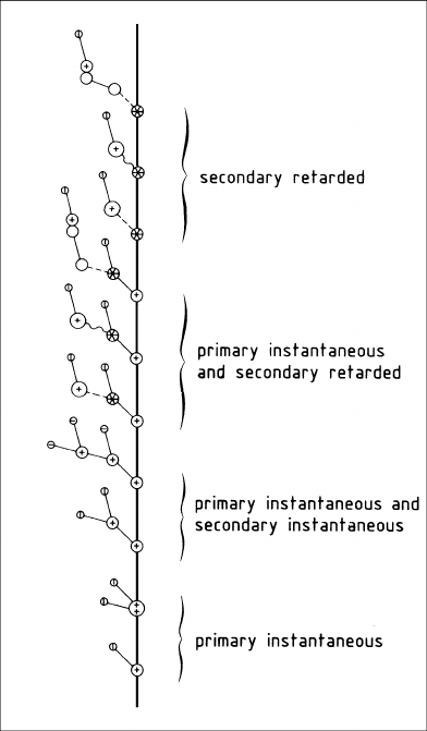
A pictorial summary of the processes discussed is given in Fig. 1.1.
1.1.3 Average Energy Required to Produce One Ion Pair
Only a certain fraction of all the energy lost by the fast particle is spent in ionization.
The total amount of ionization from all processes is characterized by the energy W
that is spent, on the average, on the creation of one free electron. We write
WN
I
= L
dE
dx
, (1.9)
where N
I
is the average number of ionization electrons created along a trajectory
of length L, and dE/dx is the average total energy loss per unit path length of the
fast particle; W must be measured for every gas mixture.
Many measurements of W have been performed since the advent of radioactiv-
ity, using radioactive and artificial sources of radiation. The amount of ionization
produced by particles that lose all their energy in the gas is measured by ionization
chambers or proportional counters. The value of W in this case is the ratio of the
initial energy to the number of ion pairs. The energy W depends on the gas – its
composition and density – and on the nature of the particle. Experimentally it is
found that W is independent of the initial energy above a few keV for electrons and
a few MeV for alpha-particles, which is a remarkable fact.
1.1 Gas Ionization by Fast Charged Particles 5
Fig. 1.1 Pictorial
classification of the ionization
produced by a fast charged
particle in a noble gas
containing molecules with
low ionization potential: (−)
electron; (+) positive ion,
single charge; (+ +) positive
ion, double charge; (+)
positive ion of the
low-ionization species; (∗)
state excited above the lower
ionization potential of the
other species; ()(+) positive
ion of noble gas molecule; ∼
photon transmission,
−− collision
When a relativistic particle traverses a layer of gas, the energy deposit is such a
small fraction of its total energy that it cannot be measured as the difference between
initial and final energy. Therefore, there is no direct determination of the appropriate
value of W, and we have to rely on extrapolations from fully stopped electrons.
A critical review of the average energy required to produce an ion pair is given
in a report of the International Commission on Radiation Units and Measurements
[INT 79]. A treatment in a wider context is provided by the book of Christophorou
[CHR 71] and by the review by Inokuti [INO 75]; see also the references quoted
in these three works. For pure noble gases, W varies between 46 eV for He and
22 eV for Xe; for pure organic vapours the range between 23 and 30 eV is typical.
Ionization potentials are smaller by factors that are typically between 1.5 and 3.
Table 1.3 contains a small selection of W -values for various gases.
Values of W measured with photons and with electrons are the same. Values of
W measured with
α
-sources are similar to those measured with
β
-sources: W
α
/W
β
is 1 for noble gases but can reach 1.15 for some organic vapours [CHR 71]. In pure