Blum W., Riegler W., Rolandi L. Particle Detection with Drift Chambers
Подождите немного. Документ загружается.

6.2 Signal Shaping 197
0.01 0.05 0.1 0.5 1 5 10
0
0.2
0.4
0.6
0.8
1
0.05 0.1 0.5 1 5 10
–10
0
|W| / W
0
–20 log W / W
0
ω t
p
ω t
p
–5
–15
–20
(a) (b)
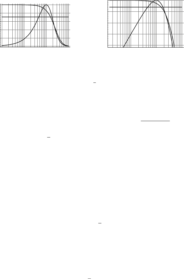
Fig. 6.15 Absolute value of the transfer functions for the unipolar and the bipolar shaper as a
function of the dimensionless number
ω
t
p
, assuming n = 4. The plot in (a) has a linear coordinate,
and the plot in (b) shows the two transfer functions in units of dB. The horizontal line indicates
the −3dB level. Both shapers attenuate frequencies higher than
ω
≈1/t
p
. The transfer function of
the bipolar shaper shows a maximum at
ω
=(
√
n −1)/t
p
and monotonically decreases for lower
frequencies. At zero frequency the transfer function of the bipolar shaper is zero
The two transfer functions are depicted in Fig. 6.15. The unipolar shaper passes
all frequencies up to the 3-dB bandwidth limit of
ω
bw
= n
2
1/(n+1)
−1/t
p
, which
evaluates to
ω
bw
≈ 1.54/t
p
for n = 4. The transfer function of the bipolar shaper
has a peak at
ω
=(
√
n −1)/t
p
and lower and higher frequencies are attenuated.
For n = 4 the peak of the transfer function is located at
ω
= 1/t
p
and the 3-dB
bandwidth limit is
ω
bw
≈ 1.81/t
p
, similar to the one from the unipolar shaper. For
our purposes it is sufficient to assume that the bandwidth limits of a unipolar and
a bipolar shaper of the same peaking time t
p
are identical. For DC signals, which
means
ω
= 0, the transfer function of the bipolar shaper is zero. The name ‘bipolar
shaper’ comes from the fact that the positive part of the signal is followed by a
negative part (‘undershoot’) of equal area, such that the time integral over the entire
signal is zero. This follows from the fact that H
bip
(0)=0, which can be seen by
using Eqs. (6.4d) and (6.4j):
lim
t→∞
g
t
−∞
h
bip
(t
)dt
= lim
s→0
s
1
s
H
bip
(s)=H
bip
(0)=0. (6.39)
In fact, for any device with a transfer function having the property W(0)=0, the
integral of the delta response w(t) is zero, which means that the positive signal part
has an area equal to the negative signal part. The same is true for any output signal
V
1
(s)=W(s)V(s) of the device:
lim
t→∞
t
−∞
v
1
(t
)dt
= lim
s→0
s
1
s
W(s)V (s)=W(0)V (0)=0. (6.40)
In physical terms, the zero in the transfer function at s = i
ω
= 0 implies that DC
signals are fully attenuated. Only sinusoidal components with frequencies
ω
> 0
pass the circuit, and because all individual sinusoidal components are bipolar the
entire signal is bipolar.

198 6 Electronics for Drift Chambers
A device with a transfer function W (s) having the property W(0)=0iscalledan
AC coupled device. If W(0) is non-zero it is called DC coupled. The drift tube circuit
discussed in Sect. 5.6.1 is an AC coupled system because the capacitor blocking the
high voltage U from the amplifier also blocks the low-frequency components of the
signal.
In the following we discuss the processing of a wire chamber signal by the two
shapers discussed above. The currents flowing into the input of the readout electron-
ics are typically not exactly equal to the current signals induced on the electrodes,
but they are already ‘shaped’ by the effects of the passive detector elements pre-
ceding the amplifier together with the input impedance of the amplifier. In order to
avoid the complications of this input circuit, which we discuss later, we consider for
the moment only the drift tube from Sect. 5.5, where the tube wall is set to potential
−U and the wire is grounded. We assume that the connection of the wire to ground
is performed through a current amplifier of zero input impedance with transfer func-
tion W
uni
or W
bip
. The induced current signal is therefore equal to the current flowing
into the amplifier and is given by the form
i(t)=
q
2t
0
ln(b/a)
1
1+t/t
0
0 < t/t
0
< t
max
=
b
2
a
2
−1. (6.41)
As the Laplace transform of this signal cannot be written in closed form we
calculate the output signal by numerical evaluation of the convolution of i(t) with
the amplifier delta response. We assume the same sensitivity g and peaking time
t
p
for the unipolar and bipolar shaper. We must therefore perform the convolution
of i(t) with gh
uni
(t) or gh
bip
(t), where we insert
τ
= t
p
/n for the unipolar and
τ
= t
p
/(n −
√
n) for the bipolar shaper. We just present the integral for the unipolar
shaper, which reads as
v(t)=g
t
0
h
uni
(t −t
)i(t
)dt
→ (6.42)
v(t)
gq
=
1
2ln(b/a)
t
0
e
t
0
t
p
t
t
0
−
t
t
0
e
−
t
0
t
p
t
t
0
−
t
t
0
n
1
1+(t
/t
0
)
dt
t
0
.
As an example we use a drift tube with a parameter b/a = 100, giving a value
of t
max
= 10
4
t
0
for the signal duration. For a t
0
value of 1 ns this evaluates to t
max
=
10
μ
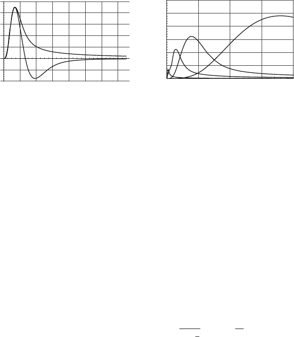
s. Figure 6.16a shows the amplifier output signals for n = 4 and a value for
t
p
/t
0
= 10. For a t
0
value of 1 ns this corresponds to an amplifier peaking time of
10 ns. The bipolar signal returns to zero after a time of t/t
0
≈ 100, while the output
signal of the unipolar shaper shows a very long tail that will lead to signal pileup at
high counting rates.
For our assumed parameters the signal has a peak of v
p
/gq = 0.22, which means
that the ballistic deficit is 78%. Figure 6.16b shows the amplifier output signal for
increasing values of t
p
/t
0
. The longer the peaking time the larger the signal and the
smaller the ballistic deficit. For t
p
> t
max
the signal peak approaches v = gq and
the ballistic deficit approaches zero. The pulse height is related to the signal charge
6.2 Signal Shaping 199
20 40 60 80 100 120 140
0.1
0.05
0.05
0.1
0.15
0.2
0.25
(a) (b)
50 100 150 200
0.1
0.2
0.3
0.4
0.5
0.6
v/gq v/gq
t
/t
0
t
/t
0
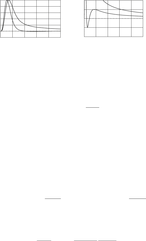
Fig. 6.16 (a) Output of a unipolar and bipolar amplifier for a drift tube signal of form 1/(t + t
0
).
The amplifier parameters are n = 4andt
p
/t
0
= 10. The ballistic deficit for this set of parameters
is 78%. (b) Amplifier output for the unipolar shaper with n = 4 and various values of t
p
/t
0
=
1,10,30, 150. The longer the peaking time the larger is the signal. For t
p
> t
max
= 10
4
t
0
, the peak
approaches a value of v
p
= gq
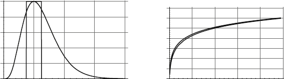
‘integrated’ by the amplifier. Let us assume that we approximate the delta response
by a ‘box’ with a duration T
I
equal to the period that the delta response exceeds 90%
of its peak value. We can state that the width of the box is equal to the ‘flat part’ of
the delta response, and for the unipolar and bipolar shaper discussed in this chapter
we have T
I
t
p
/2, as can be seen in Fig. 6.17a. We therefore assume a device with
a delta response h
box
(t)=1for0< t < T
I
and h
box
(t)=0 outside this interval. The
output signal of such a device is
v(t)=g
t
0
h
box
(t −t
)i(t
)dt
= g
t
t−T
I
i(t
)dt
(6.43)
and the peak of the signal is
v
p
= v(T
I
)=g
T
I
0
i(t
)dt
= gQ(T
I
)=
gq
2ln
b
a
ln
1+
T
I
t
0
. (6.44)
The signal peak is thus equal to the sensitivity g times the total charge induced
within the duration T
I
of the flat top of the delta response. We call the time T
I
the
integration time of the amplifier. Figure 6.17b shows the charge integrated during a
time T
I
= t
p
/2, together with the signal peak of the exact expression from Eq. (6.42).
We see that they are almost identical, which justifies the above assumptions. In
order to have no ballistic deficit, the flat top of the delta response has to be longer
than the duration of the entire signal, being 10
4
t
0
in our case. Because a signal
duration of several microseconds is usually not compatible with rate requirements
we always use only a fraction of the induced charge. However, since the induced
charge increases just with the logarithm of the integration time, it takes only a time
of 200t
0
to integrate half the charge, corresponding to a ballistic deficit of 50%. It
takes another 9800t
0
to induce the remaining 50% of the charge.
We can conclude that the peak of the amplifier output signal is proportional to
the charge integrated during the duration of the ‘flat top’ (>90% of the peak value)
200 6 Electronics for Drift Chambers
1 2 3 4
0.2
0.4
0.6
0.8
1
100 200 300 400 500
0.1
0.2
0.3
0.4
0.5
0.6
0.7
v / gq
t
p
/
t
0
t
/
t
0
p
(a) (b)
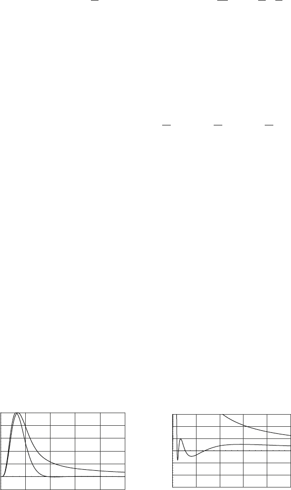
Fig. 6.17 (a) Approximation of the unipolar delta response by a box with a width corresponding
to the duration of the flat top of the signal. (b) Output signal peak for the unipolar delta response
h
uni
(t) and the box delta response h
box
(t) with a width T
I
equal to the flat top of h
uni
(t).Wesee
that interpreting T
I
as the amplifier integration time is a very good approximation
of the amplifier delta response. For wire chamber signals, where the induced charge
increases only with the logarithm of the elapsed time, this means that the ballistic
deficit is 80% for integration times of ≈ 10–20t
0
and 50% for integration times of
≈ 100–200t
0
ns. In order to have a ballistic deficit below 10% one has to integrate
for 10
3
–10
4
t
0
, corresponding to several tens of microseconds.
6.2.2 Signal Tail Cancellation
The long tails of the wire chamber signals result in undesired signal pileup even at
modestly high counting rates. There are several possibilities for removing this signal
tail. The simplest and most preferable is the use of the bipolar shaper shown in the
last section. For the example of t
0
= 1ns and t
p
= 10ns we saw that the width of the
positive signal part is ≈ 30ns followed by an undershoot of about 70 ns duration.
The baseline is ‘restored’ after a total duration of 100 ns.
There are, however, applications where such a bipolar pulse is undesirable and
we want to remove the signal tail without producing an undershoot. One reason
is the worsening of the signal-to-noise ratio for this shaping method, as pointed
out in Sect. 6.3. Another reason concerns the pulse width. We show in this section
that the ‘dead-time’ of 100 ns, mentioned in the example above, can be reduced to
about 40 ns with a unipolar shaping scheme. A third reason concerns crosstalk. We
have seen that the signal induced on the wire where the avalanche is taking place
has negative polarity and the signal induced on the neighbouring wire has positive
polarity. Applying a negative discriminator threshold to the wire signal registers
only the avalanche wire. If we read the wire signals with a bipolar shaping amplifier
there is a negative undershoot of the cross-induced signals, which can also trigger
the discriminator, resulting in crosstalk.
The standard technique for realization of unipolar tail cancellation is the use
of one or several pole-zero filters [BOI 82]. As we saw in Sect. 6.1.3, a pole-zero

6.2 Signal Shaping 201
filter with time constants
τ
1
and
τ
2
transforms an exponential signal of the form
exp(−t/
τ
1
) into an exponential signal with time constant
τ
2
(Fig. 6.8). In order
to apply such a procedure to our wire chamber signal we first approximate the
signal
i(t)=
q
2t
0
ln
b
a
1
1+t/t
0
= I
0
1
1+t/t
0
(6.45)
by a sum of exponentials with increasing time constants
τ
n
= t
0
/
α
n
:
i(t) I
0
N
∑
n=1
A
n
e
−
α
n
t/t
0
= I
0
N
∑
n=1
A
n
e
−t/
τ
n
τ
n
<
τ
n+1
. (6.46)
By choosing the number of exponential terms N sufficiently large, the signal can be
approximated to any desired accuracy. The Laplace transform of the above expres-
sion is
I(s)=L [i(t)] = I
0
N
∑
n=1
A
n
s + 1/
τ
n
. (6.47)
For illustration we use two exponentials:
i(t)=I
0
A
1
e
−t/
τ
1
+ A
2
e
−t/
τ
2
I(s)=I
0
A
1
s + 1/
τ
1
+
A
2
s + 1/
τ
2
(6.48)
and rewrite the expression as
I(s)=I
0
(A
1
+ A
2
)
(s + 1/
τ
1
)
(s + 1/
τ
)
(s + 1/
τ
2
)
τ
=
τ
1
τ
2
A
1
+ A
2
A
1
τ
1
+ A
2
τ
2
<
τ
2
. (6.49)
Applying a pole-zero filter with the time constants
τ
2
and
τ
to the signal, i.e.,
W
PZ
(s)=(s + 1/
τ
2
)/(s + 1/
τ
), results in the output signal
I
2
(s)=I(s)
s + 1/
τ
2
s + 1/
τ
= I
0
A
1
+ A
2
s + 1/
τ
1
i
2
(t)=I
0
(A
1
+ A
2
)e
−t/
τ
1
, (6.50)
which is a single exponential. This means that applying a pole-zero filter with
these specially chosen time constants to the sum of two exponential signals is
equivalent to ‘removing’ one of the exponential terms. The procedure is easily ex-
tended to the sum of several exponentials. Representing i(t) by the sum of three
exponentials we need two pole-zero filters to arrive at a single exponential, and
for N exponentials we need N −1 filters to remove all but the first exponential
term.
In order to find the constants A
n
and
α
n
=
τ
n
/t
0
that approximate i(t), we mini-
mize the area (charge) between i(t) and the sum of exponentials
kt
0
0
1
1+t/t
0
−
N
∑
n=1
A
n
e
−
α
n
t/t
0
2
dt → min. (6.51)
202 6 Electronics for Drift Chambers
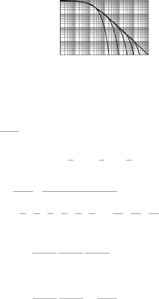
Fig. 6.18 The 1/(1 +t/t
0
)
signal together with the sum
of 1/2/3/4/5 exponentials that
approximate the signal to
within ±10%. Using three
exponentials the signal can be
approximated up to t = 100t
0
0.01 0.1 1 10 100 1000 10000
0.0001
0.001
0.01
0.1
1
t / t
0
For a given time interval T = kt
0
the number of exponentials N must be chosen
such that the signal is represented with the desired accuracy. Figure 6.18 shows
the chamber signal approximated by up to five terms. Using 1/2/3/4/5 exponen-
tial terms, we can represent the signal with 10% accuracy in a time interval of
3/20/100/350/1200t
0
.
As a numerical example we use three exponentials and two pole-zero filters:
I
0
1
1+t/t
0
I
0
A
1
e
−
α
1
t/t
0
+ A
2
e
−
α
2
t/t
0
+ A
3
e
−
α
3
t/t
0
. (6.52)
The minimization procedure in Eq. (6.51) results in the parameters
A
1
= 0.62 A
2
= 0.29 A
3
= 0.052
τ
1
t
0
= 0.92
τ
2
t
0
= 5.6
τ
3
t
0
= 57.
As before, we rewrite the expression with a common denominator
3
∑
n=1
A
n
s + 1/
τ
n
=
as
2
+ bs + c
(s + 1/
τ
1
)(s + 1/
τ
2
)(s + 1/
τ
3
)
(6.53)
a = A
1
+ A
2
+ A
3
b =
A
1
τ
2
+
A
1
τ
3
+
A
2
τ
1
+
A
2
τ
3
+
A
3
τ
1
+
A
3
τ
2
c =
A
1
τ
2
τ
3
+
A
2
τ
1
τ
3
+
A
3
τ
1
τ
2
.
Writing the polynomial in the numerator in the form as
2
+ bs + c = a(s + 1/
τ
a
)
(s + 1/
τ
b
), we get
I(s) I
0
a
(s + 1/
τ
1
)
(s + 1/
τ
a
)
(s + 1/
τ
2
)
(s + 1/
τ
b
)
(s + 1/
τ
3
)
. (6.54)
Inserting the fit parameters we have
τ
a
= 2.04t
0
and
τ
b
= 26.9t
0
. By applying two
pole-zero filters with time constants
τ
2
,
τ
a
and
τ
3
,
τ
b
we transform the signal into a
single exponential
I
2
(s)=I(s)
(s+ 1/
τ
2
)
(s+ 1/
τ
a
)
(s + 1/
τ
3
)
(s + 1/
τ
b
)
= I
0
a
s + 1/
τ
3
(6.55)
i(t)=I
0
(A
1
+ A
2
+ A
3
)e
−t/
τ
1
= I
0
0.96e
−t/0.92t
0
. (6.56)
6.2 Signal Shaping 203
20 40 60 80 100
0.2
0.2
0.4
0.6
0.8
1
(a) (b)
200 400 600 800 1000
0.02
0.01
0.01
0.02
t
/
t
0
t
/
t
0
Fig. 6.19 (a) Wire chamber signal processed by a unipolar shaper of n = 4andt
p
/t
0
= 10 together
with the same signal filtered by of two pole-zero filters. The pulse width is reduced to a length of
T 40t
0
.(b) The same signal on a smaller vertical scale, showing a tail with a height corresponding
to about 1% of the chamber signal
Figure 6.19 shows the result of applying these two pole-zero filters to the wire cham-
ber signal of Eq. (6.45), which was processed by a unipolar shaper with n = 4 and
t
p
/t
0
= 10. For this purpose we convoluted the signal v(t) from Eq. (6.42) with the
delta response of the pole-zero filter from Eq. (6.25):
v
2
(t)=
t
0
w
PZ
(t −t
)v(t
)dt
= v(t) −
t
0
τ
2
−
τ
a
τ
2
τ
a
e
−(t−t
)/
τ
a
v(t
)dt
. (6.57)
We see that the result is very satisfactory: the two pole-zero filters have considerably
reduced the signal length to about 40t
0
and only a small tail below 1% of the peak
value remains.
Improvement for Long Peaking Times: In the previous example, two of the
fitted exponential time constants were rather small (0.92t
0
and 5.6t
0
) because they
had to represent the steep part of the original wire signal at very short times. But
for amplifiers with long peaking times t
p
t
0
, the output pulse shape does not
depend on the exact form of the input at times < t
p
, but only on the signal charge
during this time. We can then achieve a closer approximation by first convoluting
the exponential terms with the amplifier response and then fitting this signal to the
chamber signal processed by the amplifier. The fit can extend over times as long as
several hundred t
0
.
v
1
(t)=g
t
0
h
uni
(t −t
)
I
0
1+t
/t
0
dt
v
2
(t)=L
−1
gH
uni
(s)I
0
N
∑
m=1
A
m
s + 1/
τ
m
.
(6.58)
The parameters A
n
,
α
n
in the analytic expression of v
2
(t) are then determined such
that the ‘amplified’ signal v
1
(t) is represented as closely as possible. The analytic
representation of v
2
(t) can be expressed by making use of the relations
L
−1
H
uni
(s)
A
s + 1/
τ
= L
−1
t
p
e
n
n!
(n + st
p
)
n+1
A
(s + 1/
τ
)
= Af(t,
τ
)
204 6 Electronics for Drift Chambers
f (t,
τ
)=t
p
n!e
n
n −
t
p
τ
−(n+1)
e
−t/
τ
−e
−nt/t
p
n
∑
m=0
1
m!
n −
t
p
τ
t
t
p
m
.
(6.59)
Thus for three exponentials the signal is expressed as
v
2
(t)=gI
0
(A
1
f (t,
τ
1
)+A
2
f (t,
τ
2
)+A
3
f (t,
τ
3
)). (6.60)
For a value of t
p
/t
0
= 10, the signal v
1
(t) is approximated to within ±10% accuracy
up to 350t
0
by the parameters
A
1
= 0.60 A
2
= 0.10 A
3
= 0.016
τ
1
t
0
= 2.48
τ
2
t
0
= 18.8
τ
3
t
0
= 191.
Using two pole-zero filters with these time constants, giving
τ
a
= 9.37,
τ
b
= 107.35
results in the output signal presented in Fig. 6.20. A small bump with a height of
0.5% of the peak value is followed by a remaining tail of only 0.25% relative height.
This is an improvement of a factor 2 compared to the previous scheme.
Although the unipolar-shaped pulse is shorter and avoids the undershoot, there
are several issues that have to be considered carefully when choosing this shaping
scheme. First, one has to evaluate the effects of the remaining signal tail, which lasts
up to 10
5
t
0
in our example. Although the tail is small, the statistical superposition
of many of them may result in significant baseline fluctuations. In addition, the pre-
cise cancellation of the signal tail requires a very good knowledge of the chamber
signal shape. Because the time constant t
0
depends on the ion mobility and applied
high voltage, the signal shape depends on the working point and the gas mixture
that is used. The optimized pole-zero filter constants are therefore in principle only
valid for a single well-defined working point. Another word of caution concerns the
realization of the pole-zero filters. Resistors and capacitors have certain production
variations. In integrated circuits, the absolute values of R and C elements have typ-
ical errors of up to 10%, so the precise realization of the time constants is rather
difficult. The tail cancellation effect is mostly defined by the so-called pole/zero
ratio
τ
1
/
τ
2
, which itself is determined by the ratio of resistors. Although ratios of
20 40 60 80 100
0.2
0.2
0.4
0.6
0.8
1
200 400 600 800 1000
0.015
0.01
0.005
0.005
0.01
0.015
t / t
0
t / t
0
(a) (b)
Fig. 6.20 (a) Application of the two pole-zero filters to the wire chamber signal, where the pole-
zero time constants were determined after processing with the unipolar shaper. (b) The same signal
on a smaller vertical scale showing a tail of only 0.25% height

6.2 Signal Shaping 205
resistors on ICs are typically correct to about 1% it is still very tedious to fine-tune
the time constants.
It is therefore advisable to use the bipolar scheme whenever possible owing to
its simplicity and insensitivity to working point variations and imprecisions of elec-
tronic elements. In the case where unipolar shaping is required for reasons outlined
in the introduction, it is usually essential to make the pole-zero time constants pro-
grammable in order to be able to compensate for process variations and adapt to
changing working points.
6.2.3 Signal Pileup, Baseline Shift, and Baseline Fluctuations
At high counting rates, when the time between signals is not long compared to
the signal pulse width, the individual signals pile up and cause a deterioration of
the signal quality. This can be calculated if one uses the fact that the individual
pulses come at random and therefore have an exponential distribution of the time
interval between any two consecutive signals. The probability P(t)dt for finding a
time interval t,t +dt is
P(t) dt =
1
τ
e
−t/
τ
dt =
ν
e
−
ν
t
dt, (6.61)
where
ν
is the average pulse rate and
τ
= 1/
ν
is the average time between two
consecutive pulses. The effect of different pulse shapes at high counting rates is
demonstrated in the four parts of Fig. 6.21, where we see a rapid random sequence
of identical pulses treated by four different shapers. We use the remainder of this
section to quantify what we see. The rate
ν
is taken to be
ν
= 5 ×10
−3
/t
0
, which
corresponds to 5 MHz when t
0
= 1ns.
For the following discussion it is useful to separate the signal into a ‘signal’
part of duration T and a ‘tail’ part (Fig. 6.22). The first high-rate effect to discuss is
signal pileup, where the ‘signal’ part of two signals arrives within a time interval that
is smaller than the signal pulse width T. This pileup results in incorrect charge or
time measurement. In a particle tracking system, the particle trajectory is typically
measured by several readout channels, and the track reconstruction can detect the
channel with incorrect charge or time measurement. Consequently the measurement
from this channel is not used in the reconstruction, which results in an inefficiency
of this channel. The signal pileup probability, or inefficiency
ε
, for a pulse width T
and a rate
ν
is given by
ε
=
T
0
ν
e
−
ν
t
dt = 1 −e
−
ν
T
≈
T
τ
for T
τ
. (6.62)
The rate requirement is therefore one key element for specification of the maximum
pulse width T , which in turn specifies the shaping strategy. The signal part of the
bipolar pulse in Fig. 6.16a has a duration of T ≈ 80t
0
while the signal part of the
206 6 Electronics for Drift Chambers
0 1000 2000 3000 4000 5000
–0.25
0
0.25
0.5
0.75
1
1.25
1.5
(a) (b)
(c) (d)
0 1000 2000 3000 4000 5000
0
0.25
0.5
0.75
1
1.25
1.5
0 1000 2000 3000 4000 5000
0
0.25
0.5
0.75
1
1.25
1.5
t/t
0
t/t
0
0 1000 2000 3000 4000 5000
–0.25
–0.25
0
0.25
0.5
0.75
1
1.25
1.5
t/t
0
–0.25
t/t
0
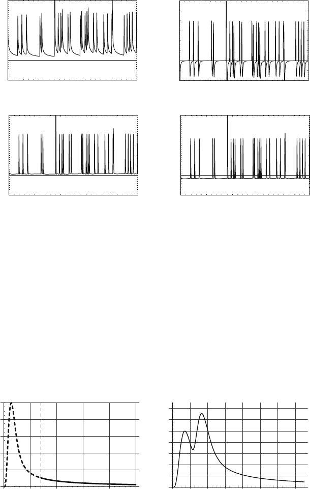
Fig. 6.21 A fast random sequence of chamber signals processed by four different shapers:
(a) unipolar shaper, (b) bipolar shaper, (c) unipolar shaper with two pole-zero filters, and (d) unipo-
lar shaper with two pole-zero filters and AC coupling. The rate dependence of the baseline for these
four shapers is treated in this subsection
unipolar pulse with two pole-zero filters in Fig. 6.20 has a length of T ≈ 40t
0
.This
causes an inefficiency of 40% for the bipolar shaper and 20% for the unipolar shaper
at the average pulse separation of 200t
0
.
The second high-rate effect is ‘tail’ pileup, where a signal is ‘sitting’ on the
superimposed tails of one or several preceding signals, causing a displacement of
the baseline. We would like to know the average value of the displacement (‘baseline
shift’) as well as its variance (‘baseline fluctuation’). The baseline fluctuations cause
a deterioration in the measurement accuracy rather than an inefficiency.
50 100 150 200 250
t
/
t0
t
/
t0
0.2
0.4
0.6
0.8
(a) (b)
1
20 40 60 80 100 120 140
0.2
0.4
0.6
0.8
1
1.2
1.4
Fig. 6.22 (a) Separation of the chamber pulse into a ‘signal’ part and a ‘tail’ part. (b) Signal pileup
leading to incorrect charge or time measurements. Removing these incorrect measurements leads
to inefficiency