Blum W., Riegler W., Rolandi L. Particle Detection with Drift Chambers
Подождите немного. Документ загружается.

6.3 Noise and Optimum Filters 217
Z(s)
V
T
(s)
V(s)
Z(s)
V(s)
= Z(s)I(s)
I
N
(s)V(s)
Linear
Active
Network
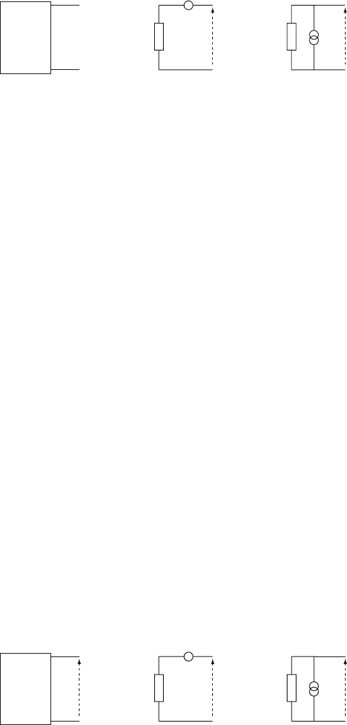
Fig. 6.30 Illustration of Thevenin’s and Norton’s theorems
calculated by the well known network rules. The voltage V
T
(s) and current I
N
(s)
are related by V
T
(s)=Z(s)I
N
(s). As an example we use the circuit of Fig. 6.29.
By shorting the voltage source and opening the current source, the impedance
of the entire network becomes Z(s)=Z
1
(s)Z
2
(s)/(Z
1
(s)+Z
2
(s)). The Thevenin
equivalent voltage is given by V
1
(s) from Eq. (6.85) and the current is therefore
I
1
(s)=V (s)/Z(s)=I(s)+V(s)/Z(s). The same is true for noise sources: the entire
network can again be represented by a single impedance Z(s) with a series volt-
age noise power spectrum w
v
( f ) or a parallel current noise power spectrum w
i
( f )
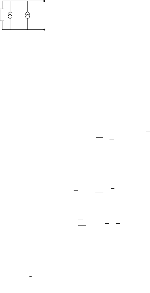
(Fig. 6.31), and the two are related by
w
v
( f )=|Z(i2
π
f )|
2
w
i
( f ) . (6.87)
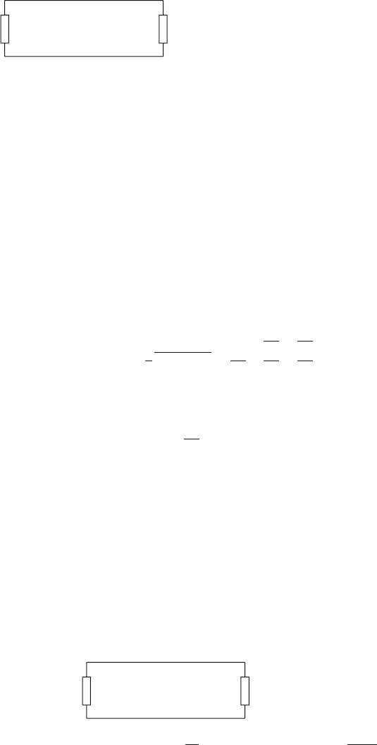
Thus we can represent the wire chamber electrode connected to an amplifier
input by a single impedance element Z(s) with a parallel current source representing
the chamber signal and a parallel current noise power spectrum representing all
electrode noise sources (Fig. 6.32).
In this way we can evaluate the relative magnitudes of signal and noise at the
amplifier input, which allows us to choose the amplifier transfer function in order to
optimize the signal-to-noise ratio at the amplifier output.
6.3.2 Noise Sources
Having the vocabulary and the tools for noise analysis at hand we can now discuss
the different noise sources in a wire chamber setup. We consider only the noise in-
herent in the detector and the amplifier and not external ‘man-made’ noise that may
originate in various electrical devices outside of the detector. Of course, any such
interference noise has to be eliminated before approaching the inherent ‘irreducible’
detector and amplifier noise.
Z(s)
w
v
(f)
w
v
(f)
Z(s)
w
v
(f)=
w
i
(f)
Linear
Network
with noise
sources
w
v
(f)
|Z(i2πf)|
2
w
i
(f)
Fig. 6.31 Thevenin’s and Norton’s theorems applied to the noise power spectra
218 6 Electronics for Drift Chambers
Z(s) w
i
(f) I(s)
Fig. 6.32 Representation of the wire chamber elements, noise sources, and the chamber signal by
a single impedance Z(s) with a single current source and a single noise power spectrum
There are many physical processes that create noise in electric circuits. The three
most important ones for particle detection are shot noise, thermal (Johnson) noise,
and flicker (1/ f ) noise.
Shot Noise
This electrical noise is based on the random arrival of the smallest quantized units
of electric charge. The name derives from an analogy with the pellets of a shotgun.
If the random sequence is governed by the arrival probability p per unit of time
alone (no correlations) one easily calculates the mean number
m of particles in an
observation time T as well as the variance,
m
2
−m
2
:
m = pT (6.88)
The actual integer number m is distributed around this mean according to the Pois-
son probability distribution
P(
m,m)=
m
m
m!
e
−m
. (6.89)
The expectation value of m
2
is therefore
∞
∑
m=0
m
2
m
m
m!
e
−m
= m+ m
2
. (6.90)
It follows that the variance is equal to the mean, a famous property of the Poisson
distribution. A power spectrum for this kind of noise exists once an electrical pulse
e
0
f (t) is associated with each noise particle carrying the elementary charge e
0
.We
have a random sequence of identical current pulses coming at a mean frequency
ν
.
Campbell’s theorem applies [RIC 44]. It states that under these circumstances the
average current
I and its variance
σ
2
I
are given by
I =
ν
e
0
∞
−∞
f (t)dt
σ
2
I
=
ν
e
2
0
∞
−∞
f (t)
2
dt. (6.91)
Applying Parseval’s theorem we can transform the expression for
σ
I
into
σ
2
I
= 2
ν
e
2
0
∞
0
|F(i
ω
)|
2
df. (6.92)

6.3 Noise and Optimum Filters 219
This can be identified with the noise power spectrum, which has the following form:
w( f )=2
ν
e
2
0
|F(i
ω
)|
2
. (6.93)
We note that the power spectrum of shot noise depends on the size of the elementary
charge. For a given current
ν
e
0
the fluctuation increases with the size of e
0
.
If we imagine f (t) to be a
δ
-function
δ
(t) we have F(i
ω
)=1 and the noise
power spectrum becomes white:
w( f )=2
ν
e
2
0
= 2e
0
I. (6.94)
This means that we can imagine white noise to be a random sequence of delta current
pulses.
Thermal or Johnson Noise
In 1906 Einstein predicted that Brownian motion of the charge carriers would lead
to a fluctuating potential between the ends of any resistance in thermal equilibrium.
The effect was first observed by Johnson [JOH 28] and its power spectrum was
calculated by Nyquist [NYQ 28].
One way to establish the voltage and current fluctuations at the ends of the con-
ductor is to sum up the contributions of the electrons that move about in thermal
equilibrium with the constituents of the conductor. Every electron moving with a
velocity u
i
down the conductor contributes a small current e
0
u
i
; this is related to
the mean energy per degree of freedom, proportional to the absolute temperature
and the resistance of the conductor. Such a microscopic derivation can be found in
[KIT 58].
A more general derivation of the noise power spectrum follows. It is based on
the insight that the electric and magnetic fields created by the movements of the
electrons themselves possess degrees of freedom of the system which are in thermal
equilibrium with their surroundings and therefore must carry the average energy
of kT/2 per degree of freedom or kT per mode of the electromagnetic field (k =
Boltzmann constant, T = absolute temperature).
In order to find the noise power spectrum, all that remains to be done is to prop-
erly count the modes of the electric and magnetic fields. This was achieved by
Nyquist [NYQ 28] in a paper immediately following the paper in which Johnson
[JOH 28] first described thermal noise. One considers two equal resistors R
1
=
R
2
= R connected by an ideal lossless transmission line as indicated in Fig. 6.33.
The transmission line is given an impedance equal to R, the resistors are in ther-
mal equilibrium at the absolute temperature T . The voltage fluctuations at R
1
are
accompanied by current fluctuations so that some electrical power P
1
is flowing
into the line at R
1
and is being absorbed in R
2
. There are no reflections because
the line is properly terminated. An equal amount of power flows from R
2
through
the transmission line into R
1
. The amount of P
1
can be connected to the vibrational
modes of the transmission line in the following way: Let L be its length and c the
220 6 Electronics for Drift Chambers
R
1
R
2
Fig. 6.33 Nyquist’s idealized arrangement of two resistors in thermal equilibrium, connected by a
lossless transmission line that has no thermal properties
velocity of propagation of the electrical signals on the line. Let the line suddenly be
isolated from the resistors by short-circuiting both ends so that the electromagnetic
waves are trapped and their modes can be counted. The nth mode has a wavelength
λ
n
= 2L/n and a frequency f
n
= nc/2
λ
, so in the frequency interval df there are
2L/cdf modes (n 1), each of which carries an average energy kT.
One half of this energy is the power emitted from R
1
during the time interval L/c,
so this power is equal to
kT d f (6.95)
in the frequency interval df. It is remarkable that the power density is independent
of f , R
1
, and the nature of the resistance.
If one wants to express the emitted power P
1
of one resistor in terms of the fluc-
tuation of the voltage V
1
(t), one may calculate the total power dissipated in the two
resistors as
2P =
1
2
(V
1
+V
2
)I =
1
2R
V
2
1
4
+
V
2
2
4
(6.96)
using I(t)=1/2(V
1
(t)+V
2
(t)/2R plus the fact that V
1
and V
2
fluctuate incoherently.
Therefore, using Eq. (6.96), we find that the voltage fluctuations per frequency unit
across a resistor is
V
2
1
= 4kTR. (6.97)
One says that the voltage noise power spectrum is
w( f )df = 4kTRd f , (6.98)
where w( f ) is expressed in V
2
/Hz [cf. Eq. (6.79)]. As it is independent of f it is
‘white’ noise.
Next we have to consider the temperature noise originating from a passive net-
work described by a complex impedance. Let the resistance R be connected to such
a network with impedance Z( f )=R( f )+iX( f ), according to Fig. 6.34 By reason-
ing according to Nyquist, as above, we know that the power transferred from the
R
2
Z(iω) = R(ω) + iX(ω)
Fig. 6.34 Resistance R and network with impedance R( f )+iX( f ) on the same temperature,
connected to each other. The noise at R is
V
2
; the noise from the network is V( f )
2

6.3 Noise and Optimum Filters 221
resistance to the network is equal to that transferred in the opposite direction. The
former is seen by simple circuit theory to be equal to
V
2
R( f )
(R + R( f ))
2
+ X( f )
2
df (6.99)
and the latter is simply equal to
V( f )
2
R
(R + R( f ))
2
+ X( f )
2
df. (6.100)
We therefore have to conclude that the voltage power spectrum of any passive net-
work is
w
v
( f )df = 4R( f )kTd f = 4kT Re[Z(i
ω
)]df. (6.101)
The equivalent parallel current noise spectrum is
w
i
( f )df =
w
v
( f )
|Z(i
ω
)|
2
= 4kT Re[1/Z(i
ω
)]df. (6.102)
Following upon Planck’s work, we see that Eq. (6.95 ff) are only valid as long as
the average energy of one mode of the electromagnetic field is much higher than the
quantum energy hf at frequency f (where h is Planck’s constant). This is actually
the case for all our electronics applications. Under quantum conditions, i.e., for
temperatures and frequencies where kT becomes comparable to hf, instead of (6.95)
the average energy becomes
hf
exp(hf/kT) −1
per mode of the electromagnetic field (6.103)
which approaches kT when kT hf.
Flicker or 1/f Noise
There is a third category characterized by increasing noise with decreasing fre-
quency. It is not one single well-defined process that causes it but rather a whole
collection, sometimes not completely understood. This ‘flicker noise’ typically oc-
curs in non-equilibrium situations in devices subjected to applied bias voltage to
which it is often proportional. Examples are the contact resistance fluctuations in
carbon microphones and carbon resistors or leakage currents in the dielectric of ca-
pacitors. It occurs in field effect transistors and in many other places discussed in
the literature [ROB 74].
The frequency dependence of the power spectrum is often near 1/ f and may
extend to very low f (on the order of 10
−2
Hz or less). It is well known that a single
relaxation process (one governed by an exponential decrease in the time response)
cannot account for the observations, but perhaps a superposition of several would
222 6 Electronics for Drift Chambers
serve. One way to parametrize the power spectrum w( f ) is to specify the frequency
f
0
at which the flicker noise is equal to the white temperature noise power w
T
( f )=
4kRT d f. The total power spectrum is then
w
tot
( f )=w
T
( f )(1+ f
0
/ f ) . (6.104)
The value of f
0
has been seen to differ from as low as 10
−2
Hz to as high as
100 MHz, but it is usually in the region of a few kHz [ROB 74]. For practical
purposes active electronic circuit components often carry a specification from the
manufacturer.
Amplifier Noise
When dealing with signals it is sufficient to represent the amplifier only by its
transfer function W (s) and input impedance Z
in
(s), without referring to the spe-
cific realization. However, the noise output signal of an amplifier depends on the
specific components of the amplifier circuit and the noise analysis is generally quite
a complex task.
It is possible to represent the effect of all the noise sources inside an amplifier
by two noise generators at the input of the device, which is treated as a noise-free
black box [MOT 93]. If the noise generators are correlated there is in addition a
complex correlation coefficient; this we may neglect here because the noise sources
are typically quite independent.
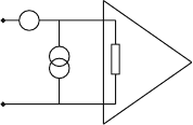
Figure 6.35 shows this model, where a voltage noise generator w
v
( f ) and a
current noise generator w
i
( f ) are placed at the input of the noiseless amplifier. Tra-
ditionally the voltage and current noise power spectra of the amplifier are called
w
v
( f )=e
2
n
( f ) and w
i
( f )=i
2
n
( f ). We call e
2
n
( f ) the series noise power spectrum
and i
2
n
( f ) the parallel noise power spectrum of the amplifier. This provides a com-
plete representation of all the internal amplifier noise sources. The voltage and
the current noise generators must be dealt with separately because their relative
importance depends on the impedance of the signal source. Once this in known
they may be contracted in a single noise generator. This is our procedure in what
follows.
w
v
(f) = e
2
n
(f)
Z
in
(s)w
i
(f) = i
2
n
(f)
Fig. 6.35 Amplifier noise model, where the noise is formulated by a pair of noise sources at the
input of a noiseless device. The voltage noise generator w
v
( f )=e
2
n
( f ) and current noise generator
w
i
( f )=i
2
n
( f ) provide a complete representation of the numerous noise sources inside the real
amplifier
6.3 Noise and Optimum Filters 223
In order to calculate the noise power spectra e
2
n
( f ) and i
2
n
( f ) one must of
course analyze the entire amplifier circuit. Although the numerous elements of the
amplifier all contribute to the noise, it is typically only the first element of the circuit
(first transistor or feedback resistor) that dominates the noise. The thermal noise,
shot noise, and 1/ f noise of this first element defines the noise performance of the
amplifier. Bipolar transistors or field effect transistors are the classical basic build-
ing blocks for detector readout electronics. In semiconductor devices incorporating
a p-n junction, the charge carriers interact with fields due to applied external volt-
ages only in the depletion layer at the junction, which is a region that is distinct
from the region where their statistical properties are established. Bipolar transistors
are therefore typical shot-noise-limited devices. The noise power spectra are then
given combinations of 2e
0
I
c
,2e
0
I
b
, and 2e
0
I
e
where I
c
,I
b
,I
e
are the collector, base,
and emitter currents.
If the interaction region with the external fields coincides with the region where
the carrier fluctuations are generated and the carriers remain approximately in ther-
mal equilibrium during their interaction, the thermal (Johnson) noise will dominate.
Field effect transistors, where the fluctuations are established in the channel, are
typical thermal-noise-limited devices [ROB 74]. The 1/ f noises of bipolar and field
effect transistors show characteristic differences which have to be considered in the
choice of electronics technology.
However, the purpose of our discussion is not the design of the amplifier but
rather it is the other way around. By comparing the wire chamber signal and
the noise due to the passive components of the wire chamber with the amplifier
noise at the input of the amplifier we can define the acceptable magnitudes of the
amplifier noise. This procedure results in a specification for acceptable amplifier
noise.
Because the shot noise and thermal noise are white noise sources we can define
an equivalent noise resistance R, where w
0
= 4kTR at T = 295K gives a power
spectrum equal to the one from the input transistor. Although the parallel noise i
2
n
and series noise i
2
n
can both show 1/ f noise, we limit ourselves to the following
amplifier noise spectra:
e
n
( f )
2
= 4kTR
s
+ B/(2
π
f ) i
2
n
( f )=4kT/R
p
. (6.105)
The series noise resistance R
s
, the parallel noise resistance R
p
, and flicker noise
coefficient B specify the noise behaviour of the amplifier at a given working point.
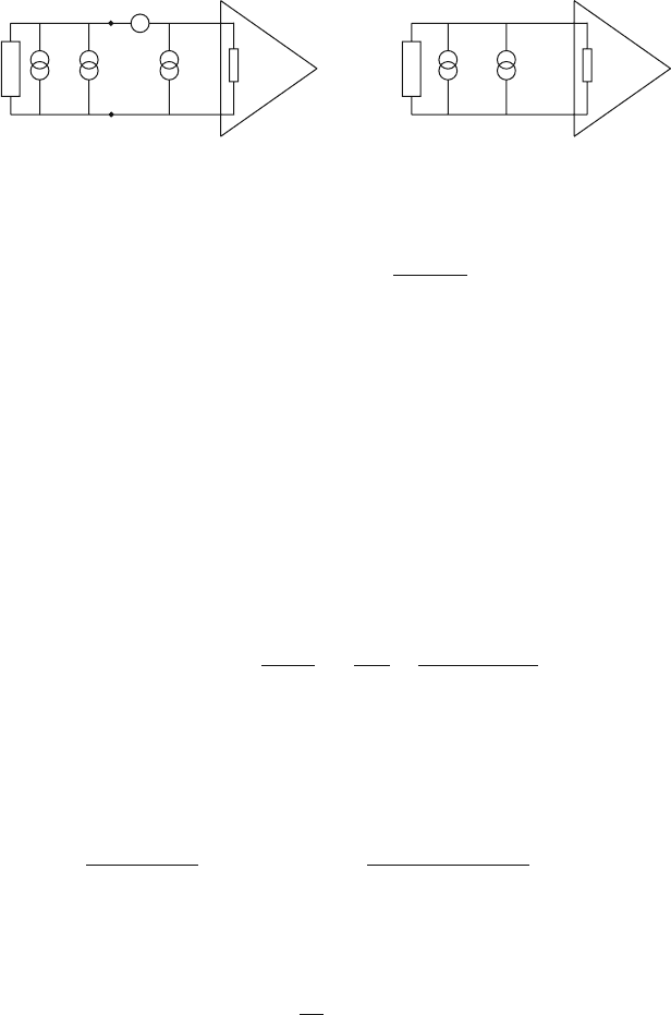
Noise in a Readout Channel, Electrode+
+
+Amplifier
We now have all the ingredients necessary to calculate the noise levels for a readout
channel of a wire chamber. We connect the detector model from Fig. 6.32 to the
amplifier model from Fig. 6.35 and perform one final simplification: The voltage
noise source e
2
n
can be transformed into a current noise source by using Eq. (6.87),
and the resulting current noise sources can be contracted into one; the resulting
power spectrum assumes the form
224 6 Electronics for Drift Chambers
e
n
2
(f)
i
n
2
(f)
w
i
(f)
Z(s) Z(s)
=
Z
in
(s)
gH(s)
gH(s)
I(s) w(f)I(s)
Z
in
(s)
Fig. 6.36 All noise sources collected into a single current noise source at the amplifier input. This
is our universal model for the ensemble of chamber signal source plus amplifier
w( f )=w
i
( f )+i
2
n
( f )+
e
2
n
( f )
|Z(i
ω
)|
2
. (6.106)
The current noise spectrum w( f ) is called equivalent input noise. We thus have
represented the entire readout channel by the chamber impedance Z(s), the par-
allel current noise density w( f ), the amplifier input impedance Z
in
(s), and the
chamber signal I(s) (cf. Fig. 6.36). Note that w( f ) is independent of the ampli-
fier’s gain and its input impedance. It is this property that makes the equivalent
input noise the most useful index upon which to compare the noise characteris-
tics of various amplifiers and devices. Summarizing the previous section, we note
that the noise components of Eq. (6.106) are as follows: The thermal chamber
noise w
i
( f ) is caused by the dissipative elements in the wire chamber through
w
i
(
ω
)=4kT Re[1/Z(i
ω
)]. The amplifier noise is represented by the parallel noise
resistance R
p
, the series noise resistance R
s
, and the coefficient for the 1/ f
noise:
w(
ω
)=4kTRe
1
Z(i
ω
)
+
4kT
R
p
+
4kTR
s
+ B/
ω
|Z(i
ω
)|
2
. (6.107)
The amplifier input impedance Z
in
(s) enters when we calculate the signal and
noise at the output of the amplifier. The fraction of current flowing into the amplifier
is Z/(Z + Z
in
), so the chamber current signal and the noise current flowing into the
amplifier are
I
in
(s)=
Z(s)
Z(s)+Z
in
(s)
I(s) w
in
( f )=
|Z(i
ω
)|
2
|Z(i
ω
)+Z
in
(i
ω
)|
2
w( f ). (6.108)
Finally, the amplifier output signal V (s) and the variance of the amplifier output
noise
σ
2
v
are
V(s)=gH(s)I
in
(s)
σ
2
v
=
1
2
π
∞
0
w
in
(
ω
)g
2
|H(i
ω
)|
2
d
ω
. (6.109)
In the following we use these results to discuss the three most important elec-
trode configurations: cathode readout, wire readout, and a terminated transmission
line channel. We want to see their behaviour for both a bipolar and a unipolar
shaper.

6.3 Noise and Optimum Filters 225
6.3.3 Noise in Wire Chambers
Cathode Channel
This case is relatively simple because Z(s) is given only by the chamber capacitance
C
D
, and the parameters of the universal model are
Z(s)=
1
sC
D
I(s)=I
ind
(s) w
i
(
ω
)=4kTRe[1/Z(i
ω
)] = 0. (6.110)
The capacitor C
D
is not a source of noise because it contains no dissipative elements.
The equivalent input noise defined in Eq. (6.107) is therefore given by
w( f )=
4kT
R
p
+ 4kTR
s
ω
2
C
2
D
+ B
ω
C
2
D
. (6.111)
For the readout electronics we take the unipolar and bipolar shapers H
uni
(s) and
H
bip
(s) from Sect. 6.2 and an amplifier input impedance Z
in
= R
in
that is neg-
ligible compared to the detector impedance Z. We thus assume that |Z(i
ω
)| =
1/
ω
C
D
R
in
. This is a good approximation for f 1/2
π
R
in
C
D
, which for a
typical amplifier input resistance of 50
Ω
and a detector capacitance of 20 pF eval-
uates to f 200MHz. We set Z
in
= 0 for Eq. (6.108) and have I
in
(s)=I(s) and
w
in
(
ω
)=w(
ω
).
Now we can calculate the amplifier output noise according to Eq. (6.109). We
first need the expression |H(i
ω
)|
2
for the unipolar and the bipolar shapers. H(i
ω
) is
the Fourier transform of the normalized delta response; it was specified in Eq. (6.37)
and depends on the number of stages that make up the shaping circuit (cf. Fig. 6.13);
t
p
is the peaking time of both the unipolar and the bipolar shaper. We obtain
|H
uni
(i
ω
)|
2
=
(e
n
t
p
n!)
2
[n
2
+(
ω
t
p
)
2
]
n+1
|H
bip
(i
ω
)|
2
=
1
n
(e
r
t
2
p
n!)
2
ω
2
[r
2
+(
ω
t
p
)
2
]
n+1
, (6.112)
where r = n −
√
n as the peaking times are the same. The integration over all fre-
quencies for
σ
v
leads to integrals of the form
x
m
/(a
2
+ b
2
x
2
)
n+1
, which can be
written in closed form as
∞
0
x
2k
(a
2
+ b
2
x
2
)
n+1
dx =
1
a
2n−2k+1
b
2k+1
π
2
1
n!4
n
(2k)!
k!
(2n −2k)!
(n −k)!
,
∞
0
x
2k+1
(a
2
+ b
2
x
2
)
n+1
dx =
1
a
2n−2k
b
2k+2
1
2
k!(n −k −1)!
n!
.
(6.113)
The variance of the amplifier output noise is then
σ
2
v
=
1
2
π
∞
0
4kT
R
p
+ 4kTR
s
ω
2
C
2
D
+ B
ω
C
2
D
|gH(i
ω
)|
2
d
ω
, (6.114)
226 6 Electronics for Drift Chambers
e
n
2
(f)
i
n
2
(f)
w
i
(f)
Z(s)
=
Z
in
(s)
gH(s)
gH(s)
I
ind
(s) w(f)I(s)
C
D
Z
in
(s)
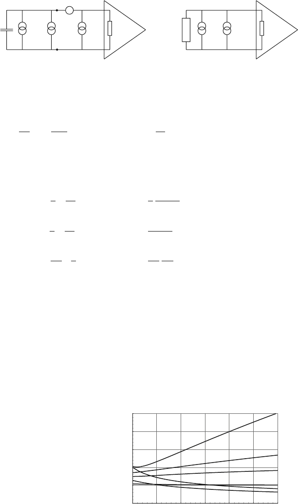
Fig. 6.37 Cathode pad connected to to an amplifier and the universal model of the readout channel
which finally evaluates to
σ
2
v
g
2
=
4kT
R
p
K
p
t
p
+
+
4kTR
s
C
2
D
,
K
s
t
p
+
+
BC
2
D
,
K
f
= ENC
2
. (6.115)
K
p
,K
s
and K
f
are dimensionless parameters given by
Unipolar Bipolar
K
p
=
1
2
e
2n
2n
(2n −1)!
1
2
e
2r
(2r)
2n
r(2n −2)!
K
s
=
1
2
e
2n
2n
n
2
(2n −2)!
3e
2r
(2r)
2n
r
3
(n −1)(2n −4)!
K
f
=
1
4
π
e
n
2n
n!(n −1)!
1
4
π
e
2r
r
2n
r
2
(n −1)!(n −2)!
(6.116)
These parameters are of the order of unity and they are shown in Fig. 6.38. The
noise r.m.s. is written as
σ
v
= gENC, where ENC is the so-called equivalent noise
charge.
We saw earlier that injecting a delta current Q
δ
(t) into an amplifier of sensitivity
g results in an amplifier output pulse height of V = gQ. Therefore, injecting a delta
signal with charge Q = ENC into the amplifier results in an output pulse height
equal to the r.m.s of the amplifier output noise. The ENC characterizes the noise
level independently of the amplifier sensitivity g and is the most useful quantity for
comparing the noise behaviour of different amplifiers.
Fig. 6.38 The parameters K
p
,
K
s
,andK
f
for the unipolar
and the bipolar shaper
represented as continuous
functions of n, the number of
stages. For n = 4theylie
between 0.5 and 1.5
3 4 5 6 7 8
n
0.5
1
1.5
2
2.5
K
K
s
(bip)
K
f
(bip)
K
p
(bip)
K
s
(unip)
K
f
(unip)
K
p
(unip)