Blum W., Riegler W., Rolandi L. Particle Detection with Drift Chambers
Подождите немного. Документ загружается.

6.5 Electronics for Time Measurement 237
surface towards the cathode and the amplifier output signal v
0
(t) for such an input
pulse:
i
0
(t)=
I
0
1+t/t
0
v
0
(t)=g
t
0
h(t −t
)i
0
(t
)dt
. (6.147)
From Fig. 6.16 and Eq. (6.44) we know that the peak v
0p
and the peak time T
p
of
v
0
(t) are approximately given by
v
0p
≈ gI
0
t
0
ln(1+t
p
/2t
0
) T
p
≈t
p
(6.148)
for both the unipolar and the bipolar shaper.
6.5.1 Influence of Electronics Noise on Time Resolution
In order to isolate the effect of electronic noise from chamber intrinsic fluctuations
we first assume that m electrons arrive at the wire at exactly the same time and that
all electrons experience the same avalanche multiplication G. The induced current,
the output signal and the peak of the output signal are then
i(t)=mGi
0
(t) v(t)=mGv
0
(t) v
p
≈ gmGI
0
t
0
ln(1+t
p
/2t
0
) (6.149)
Applying a discriminator with a threshold v
T
to the amplifier output signal results
in a measured time t
T
which, in the absence of electronic noise, is strictly related to
the arrival time of the electrons (Fig. 6.45). If electronic noise with an r.m.s of
σ
v
is superimposed on the output signal v(t), the edge time of the discriminator output
will vary, as illustrated in Fig. 6.46a. From the figure it is evident that the r.m.s. of
the discriminator output time jitter is
σ
t
=
σ
v
k
=
gENC
k
k = v
(t
T
), (6.150)
where k is the slope of v(t) at the threshold level. The slope k is proportional to
v
p
/T
p
,sowehave
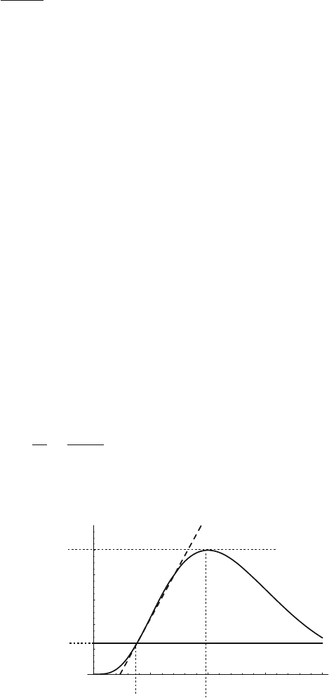
Fig. 6.45 Definition of the
slope k at the threshold
crossing, the signal peak time
T
p
, and the signal peak v
p
5 10 15 20
0.2
0.4
0.6
0.8
1
0
Threshold
v
p
v
T
t
T
T
p
Slope k
Time (ns)
238 6 Electronics for Drift Chambers
5 10 15 20
Time (ns)
20
40
60
(a) (b)
80
Signal (mV)
Threshold
σ
noise
σ
time
5 10 15 20 25 30
0.25
0.5
0.75
1
1.5
0
t
p
(ns)
r.m.s (ns)
1.25
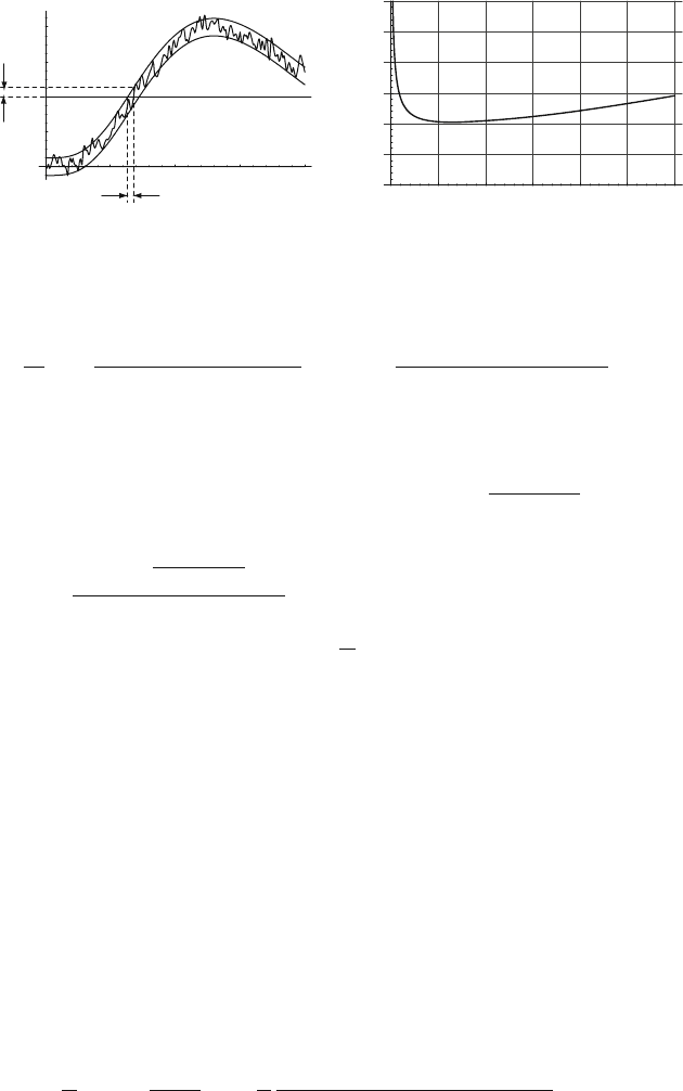
Fig. 6.46 (a) Electronic noise resulting in time jitter. (b) Dependence of
σ
t
on the amplifier peaking
time for a cathode readout channel and the parameters C
d
= 20 pF, R
p
= 10 k
Ω
, R
s
= 150
Ω
,I
0
t
0
=
e
0
/2ln(100),m = 10,G = 10
4
,t
0
= 1ns,c
1
= 2, unipolar shaper with n = 4
k ∝
v
p
T
p
= c
1
gmGI
0
t
0
ln(1+t
p
/2t
0
)
t
p
σ
t
=
t
p
ENC
c
1
mG I
0
t
0
ln(1+t
p
/2t
0
)
, (6.151)
where c
1
is a constant with a value of c
1
≈ 1.5 −2.5. For faster signal rise times,
i.e., for smaller values of t
p
, the time jitter
σ
t
is reduced. We must, however, keep
in mind that the ENC also depends on the amplifier peaking time t
p
as given by
Eq. (6.115). Neglecting 1/ f noise we found ENC(t
p
)=
A/t
p
+ Bt
p
for a typical
cathode pad readout channel. Thus, for the time jitter we get
σ
t
(t
p
)=
t
p
A/t
p
+ Bt
p
c
1
mG I
0
t
0
ln(1+t
p
/2t
0
)
A = 4kTR
s
C
2
d
K
s
B = 4kTK
p
/R
p
. (6.152)
For small values of t
p
we find
σ
t
∝ 1/
√
t
p
; for large values of t
p
the expression
increases as t
3/2
p
/lnt
p
. We therefore have an amplifier peaking time t
p
for which the
slope-to-noise ratio
σ
v
/k and, therefore, the time jitter
σ
t
become minimal. It can
be shown that the above expression has a minimum at t
p
≤ 8t
0
for any choice of
parameters. Figure 6.46b shows an example of the time jitter versus peaking time
for some typical parameters of a cathode channel.
Formally, the problem of minimizing the noise-to-slope ratio, or maximizing the
slope-to-noise ratio, can be studied in the same way as the question of the maximum
achievable signal-to-noise ratio treated earlier. The formulation of the problem is the
following: A signal F(i
ω
) with a superimposed noise of power spectrum w(
ω
) is
processed by an amplifier with transfer function H(i
ω
). Which transfer function
H(i
ω
) maximizes the slope to noise ratio?
The slope of the amplifier output signal g(t) is dg(t)/dt = g
(t), which in the
frequency domain corresponds to a multiplication of G(i
ω
) with i
ω
. The slope-to-
noise ratio is
k
σ
2
=
g
(t
m
)
σ
2
=
1
π
+
∞
−∞
i
ω
F(i
ω
)H(i
ω
)e
i
ω
t
m
d
ω
,
2
∞
−∞
w(
ω
)|H(i
ω
)|
2
d
ω
. (6.153)
6.5 Electronics for Time Measurement 239
Proceeding as before we find the maximum achievable slope-to-noise ratio
k
σ
2
≤
2
π
∞
0
|
ω
F(i
ω
)|
2
w(
ω
)
d
ω
(6.154)
with the optimum transfer function H(i
ω
) and the output signal G(i
ω
) being
H(i
ω
)=i
ω
F
∗
(i
ω
)
w(
ω
)
e
−i
ω
t
m
G(i
ω
)=i
ω
|F(i
ω
)|
2
w(
ω
)
e
−it
m
ω
. (6.155)
We realize that H(i
ω
) and G(i
ω
) differ only by the factor i
ω
from the filters op-
timizing the signal-to-noise ratio that we found earlier. Since a multiplication with
i
ω
in the frequency domain corresponds to the derivative in the time domain we can
conclude:
For a given signal f (t) and noise power spectrum w(
ω
), the amplifier delta
response that maximizes the slope-to-noise ratio is equal to the derivative of the
amplifier delta response that maximizes the signal-to-noise ratio.
Since the amplifier output signal for maximizing the signal-to-noise ratio is sym-
metric around t = 0, the amplifier output signal optimizing the slope-to-noise ratio
is antisymmetric around zero and the maximum slope-to-noise ratio is found at the
zero crossing timer of the signal (Fig. 6.47).
6.5.2 Influence of Pulse-Height Fluctuations on Time Resolution
We now consider the same situation as before, where m electrons arrive at the same
time at the sense wire, but we let the number m fluctuate from event to event accord-
ing to a distribution p(m) with an average of
m and an r.m.s. of
σ
m
(Fig. 6.48a).
Although all the electrons arrive at the same time, we find different threshold
5 10 15 20 25
1
0.5
0
0.5
1
Time (ns)
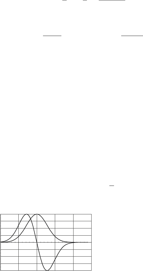
Fig. 6.47 Example for the output signal of two optimum filters. The symmetric curve is the output
signal for a filter that maximizes the signal-to-noise ratio. The antisymmetric curve is the output of
a filter that maximizes the slope-to-noise ratio. The maximum slope-to-noise ratio is found at the
zero crossing. The delta response of the filter that maximizes the slope-to-noise ratio is equal to
the time derivative of the delta response for the filter that maximizes the signal-to-noise ratio. The
same is true for the output signals of the two filters
240 6 Electronics for Drift Chambers
Time (ns)
Threshold
(a)
5 10 15 20 25
–1
–0.5
0.5
1
0
Time (ns)
(b)
5 10 15 20
0.2
0.4
0.6
0.8
1
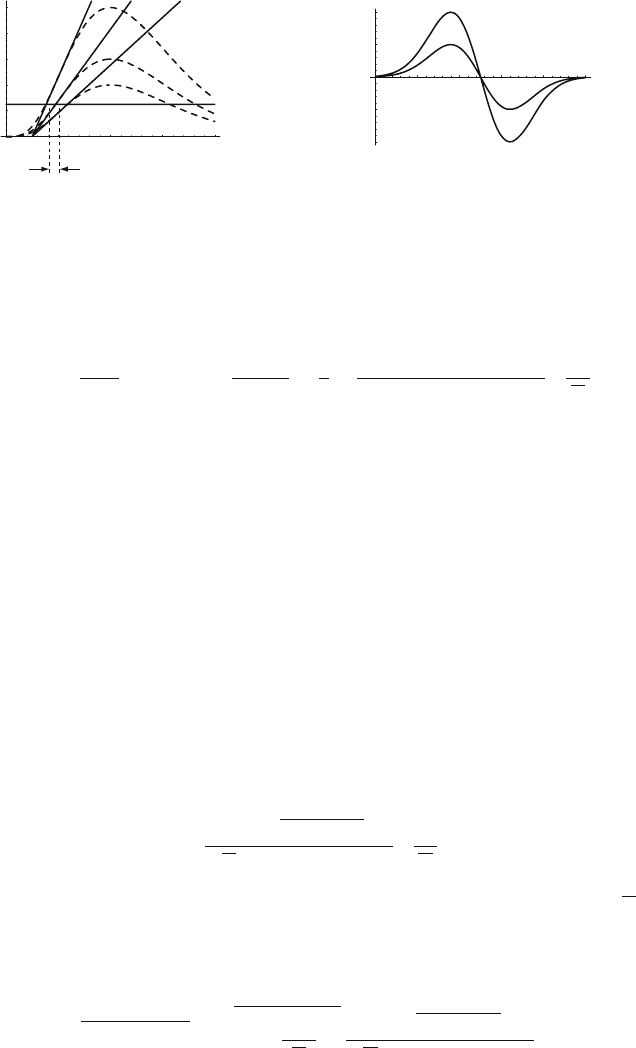
Fig. 6.48 (a) Variations of the pulse height result in different threshold crossing times. The effect
is called ‘time walk’. (b) The zero crossing time of a bipolar pulse is independent of the pulse
height
crossing times owing to the pulse-height variations of the signal, an effect that is
called ‘time walk’. The threshold crossing time and its variance are
t
T
(m)=
v
T
k(m)
σ
t
≈
σ
m
dt
T
(m)
dm
|
m=m
=
t
p
v
T
c
1
mGI
0
t
0
ln(1+t
p
/2t
0
)
σ
m
m
.
(6.156)
We see that the time walk decreases linearly with the threshold and the peaking
time and we therefore want fast electronics and the lowest possible threshold for
achieving the best time resolution. However, the lowest possible threshold is again
determined by the noise. The frequency f
T
of the noise threshold crossings for a
threshold v
T
is given by
f
T
= f
zero
e
−v
2
T
/2
σ
2
v
, (6.157)
where f
zero
is the number of zero crossings from Eq. (6.83) [RIC 44]. Setting the
threshold v
T
to 1,2, 3, 4, 5 times the noise r.m.s. results in a threshold crossing fre-
quency of 0.6, 0.14, 0.01, 3.3 ×10
−4
,3.7 ×10
−6
times f
zero
. With f
zero
being in the
range of 10–100 MHz we have to set the threshold v
T
to at least five times the noise
r.m.s. in order to arrive at a noise count rate of less than 100 Hz. We use v
T
= 5
σ
v
in the following. The discriminator threshold v
T
is typically expressed as a charge
according to v
T
= gQ
T
in order to arrive at expressions independent of the ampli-
fier sensitivity. The amplifier output noise is
σ
v
= gENC, and we therefore have a
threshold of Q
T
= 5ENC:
σ
t
=
t
p
5
A/t
p
+ Bt
p
c
1
mGI
0
t
0
ln(1+t
p
/2t
0
)
σ
m
m
. (6.158)
This expression is equal to the expression for the time jitter up to a factor 5
σ
m
/m.
Therefore the peaking time that minimizes the jitter due to electronic noise also
minimizes the jitter due to pulse-height variations. The combined effect of electronic
noise and pulse-height fluctuations becomes
σ
t
=
"
σ
2
jitter
+
σ
2
walk
=
#
1+
5
σ
m
m
2
t
p
A/t
p
+ Bt
p
c
1
mGI
0
t
0
ln(1+t
p
/2t
0
)
. (6.159)
6.5 Electronics for Time Measurement 241
If the relative pulse-height variations
σ
m
/m are greater than one, which is usually
the case in wire chambers, the time resolution is dominated by the pulse-height
variations and not by the jitter from electronic noise. On the other hand, it is the
noise that sets the lower limit on the threshold level, so it is the noise alone that
determines the time resolution owing to jitter and walk.
There are numerous ways of eliminating this pulse-height dependence of the
threshold crossing time. One can, for instance, exploit the fact the zero crossing
time of a bipolar-shaped pulse is independent of the signal amplitude, which follows
directly from the linearity of the system, as shown in Fig. 6.48b. Another possibility
is the use of a so-called constant fraction discriminator that uses a threshold which
is always set to a certain fraction of the signal peak. These techniques are applicable
when the arrival time spread of the electrons is negligible compared to noise and
pulse-height variation effects. In the next section we investigate how variation in the
electron arrival time influences the time resolution.
6.5.3 Influence of Electron Arrival Time Fluctuations
on Time Resolution
In the previous section we assumed that the number of electrons arriving at the wire
varies from event to event, but that all the electrons arrive at the same time. Now we
include the effect that the m individual electrons arrive at different times t
1
, t
2
....t
m
.
The arrival times of the electrons as well as the number of electrons m fluctuate from
event to event. In Sect. 7.4 it is shown that the average electron arrival time gives
the best timing only when the diffusion dominates the arrival spread, as for distant
tracks in a TPC.
For short drift distances, the primary ionization fluctuations together with effects
such as track inclination and path length variations dominate, and the first arriving
electrons show the smallest arrival time fluctuations. For geometries like the drift
tube, the average electron arrival time shows a very large r.m.s. even for long drift
distances because the last arriving electrons always originate close to the tube wall
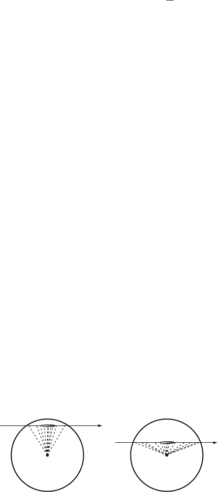
and therefore have no correlation with the drift distance (Fig. 6.49). To study the
effect of the arrival time spread we first investigate the bipolar shaping scheme,
Fig. 6.49 Electron drift lines in a drift tube. The distance of the track from the wire is determined
by the first arriving electrons. The last arriving electrons originate from the tube wall and have no
correlation with the track distance
242 6 Electronics for Drift Chambers
5 10 15 20
2
1
1
2
Time (ns)
15
20 25 30
0.5
1
1.5
2
2.5
3
12.5 13 13.5 14 14.5 15
0.3
0.4
0.5
9.5
10 10.5 11 11.5 12
0.4
0.2
0.2
0.4
0
Time (ns)
Time (ns)
(a)
(b)
(c) (d)
Time (ns)
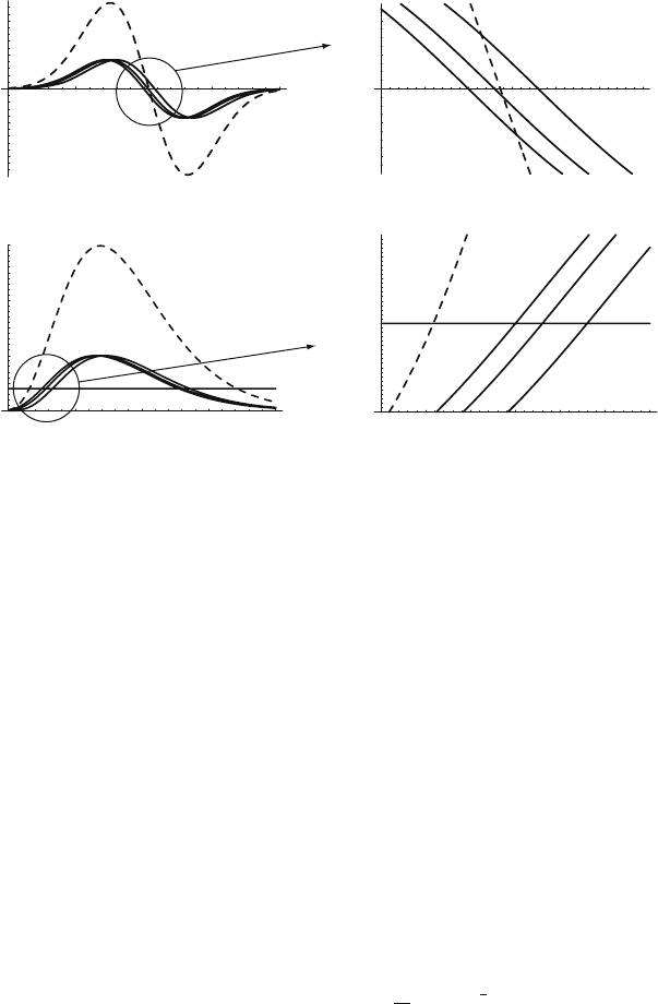
Fig. 6.50 Pulses from three electrons arriving at the wire at different times. The solid lines show
the pulses of the individual electrons; the dotted lines correspond to the sum of the pulses giv-
ing the measured chamber signal. Parts (a) and (b) show the bipolar-shaped signals where the
time measurement is given by the zero crossing of the chamber signal. Parts (c) and (d) show
the unipolar-shaped signals where the time measurement is given by the threshold crossing of the
chamber signal. The two schemes have distinctly different timing properties
where the zero crossing of the signal determines the measurement time. Figure 6.50a
shows the signals from three individual electrons arriving at different times and the
resulting chamber signal which is the sum of the individual electron signals. Around
the zero crossing the electron signals can be approximated by a straight line with a
slope −k (Fig. 6.50b), and the individual electron signals v
i
(t) and the resulting
signal v(t) can be approximated by
v
i
(t)=−k(t −t
i
) v(t)=
m
∑
i=1
v
i
(t)=−kmt−k
m
∑
i=1
t
i
. (6.160)
The zero crossing time t
T
of the signal v(t) is
v(t)=0 → t
T
=
1
m
m
∑
i=1
t
i
= t (6.161)
and equal to the average arrival time of the m electrons. This scheme is therefore
applicable for the ‘diffusion dominated’ cases mentioned above.
If we want the nth electron to give the timing information we can imagine an
amplifier that produces a step function output signal of amplitude v
0
for a single
6.5 Electronics for Time Measurement 243
electron. The step functions of the individual arriving electrons would therefore pile
up and by setting the threshold to v
T
= nv
0
we would measure the arrival time of the
nth electron. However, true step function requires an amplifier of infinite bandwidth,
and a realistic step function will take a certain time to rise from zero to v
0
. This time
must be shorter than the time between arriving electrons such that the pulses are
really piling up. Since the time between the first arriving electrons is typically much
less than a nanosecond, the bandwidth of such an amplifier must be extremely broad,
and the corresponding large noise might not allow a threshold that is low enough to
record the early electrons. In some rare cases this might still be a viable option.
Typically the amplifier peaking time is much longer than the time intervals between
arriving electrons and it is not the pulse heights but the slopes of the individual
electrons that pile up as shown next.
Figure 6.50c shows the signals from three individual electrons and the resulting
chamber signal. The time information is given by the threshold crossing time of the
leading edge of the chamber signal. The signals v
i
(t) from the individual electrons
can again be approximated by ‘straight lines’, as indicated in Fig. 6.50d, but in
contrast to the bipolar shape from before, these straight lines do not cross the zero
line, but start from zero at t = t
i
. This is illustrated in Fig. 6.51. A single electron
arriving at time t
i
produces the signal
v
i
(t)=k(t −t
i
)
Θ
(t −t
i
) v(t)=
m
∑
i=1
k(t −t
i
)
Θ
(t −t
i
). (6.162)
The chamber signal is therefore
v(t)=0 t < t
1
v(t)=k(t −t
1
) t
1
< t < t
2
v(t)=k(t −t
1
)+k(t −t
2
) t
2
< t < t
3
etc.
(6.163)
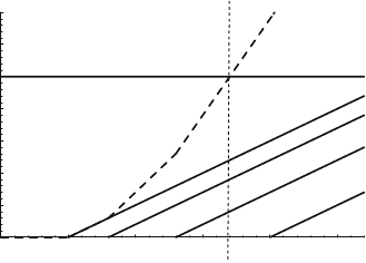
Fig. 6.51 Four single
electrons arriving at different
times and producing signals
with slope k. The sum of the
individual signals gives the
chamber signal, which
changes the slope by k
whenever a new electron
arrives
0.5 1 1.5 2 2.5
0.5
1
1.5
2
2.5
3
3.5
0
Time (ns)
Threshold v
T
t
1
t
2
t
3
t
T
t
4

244 6 Electronics for Drift Chambers
and in general we get
v(t)=
n
∑
i=1
k(t −t
i
)=knt−k
n
∑
i=1
t
i
t
n
< t < t
n+1
. (6.164)
Whenever a new electron arrives the slope changes by k, and after the arrival of the
nth electron the signal slope is k
s
= nk. The threshold crossing time t
T
is
v(t)=v
T
→ t
T
=
1
n
n
∑
i=1
t
i
+
v
T
kn
=
t
<n
+
v
T
kn
if t
n
< t
T
< t
n+1
. (6.165)
We see that the threshold crossing time is equal to the average arrival time of the n
electrons that arrived before the threshold crossing plus another term that is inversely
proportional to n. Figure 6.51 shows an example in which four electrons arrive at
times t
1
,t
2
,t
3
, and t
4
. The chamber signal crosses the threshold before the arrival of
the fourth electron, so we have n = 3 and the threshold crossing time is
t
T
=
1
3
(t
1
+t
2
+t
3
)+
v
T
3k
. (6.166)
If all the electrons arrive at the same time t = 0 we are left with only the second
term, which is equal to the expression for the time walk discussed in the previous
section. We can therefore state that the first term is due to the electron arrival time
spread and the second term to the varying number of electrons that contribute to the
signal at the threshold crossing time. However, the two expressions correlate in a
complex way.
If we want to explicitly calculate the threshold crossing time distribution and its
r.m.s., it is not sufficient to know the average and r.m.s of the arrival distribution for
the nth electron. The threshold crossing time depends on the arrival times of all n
electrons, so we need the probability density
P(t
1
,t
2
,t
3
...)dt
1
dt
2
dt
3
..., (6.167)
which gives the probability that the first electron arrives in the time interval t
1
,t
1
+
dt
1
, the second arrives in the time interval t
2
,t
2
+dt
2
, etc. The distribution P(t
1
,t
2
...)
is typically generated with a Monte Carlo simulation program. Instead of finding an
analytic parametrization of the Monte Carlo generated distributions and evaluating
the integrals of the probability distribution it is much easier to record the arrival
time pattern t
1
,...t
m
for each Monte Carlo event and to find the chamber signal by
superimposing the single-electron pulse v
0
(t) according to
v(t)=
m
∑
i=1
v
0
(t −t
i
). (6.168)
By adding the expected noise signal to v(t) we find a set of pulses from which
we can calculate the threshold crossing times and therefore the time r.m.s. This
6.5 Electronics for Time Measurement 245
procedure is very fast and by varying the threshold and electronic parameters it is a
straightforward task to find the optimum electronic parameters.
We can, on the other hand, get a good qualitative idea about the optimum elec-
tronic parameters. If we assume that the first electron arrives at t = 0 and the
following electrons arrive at regular time intervals
Δ
t, the chamber signal v(t)
becomes
v(t)=
∑
i
k(t −i
Δ
t)
Θ
(t −i
Δ
t) ≈
kt
2
2
Δ
t
. (6.169)
The threshold crossing time t
T
and the number of electrons n having arrived at the
wire before t
T
are
t
T
≈
2v
T
Δ
t
k
n ≈
t
T
Δ
t
=
2v
T
k
Δ
t
. (6.170)
If the electrons are separated by 2
Δ
t instead of
Δ
t the threshold crossing time is a
factor
√
2 later. The two ‘events’ with an electron separation
Δ
t and 2
Δ
t are shown
in Fig. 6.52. The time difference
Δ
t
T
between the two threshold crossings for the
two signals is
Δ
t
T
=(
√
2 −1)
2v
T
Δ
t
k
. (6.171)
The variation of the threshold crossing time therefore decreases for lower threshold
and large slope (faster electronics) as was the case for pulse height fluctuations and
time walk. The lower threshold limit is again determined by the noise level. The
effects of pulse-height variation, discussed in the previous section, and the arrival
time fluctuations cannot be separated because they are highly correlated. A larger
primary ionization will also result in shorter time intervals between arriving elec-
trons. The only effect that can be added in square is the jitter from electronic noise
that is independent of the electron statistics.
On the one hand, lowering the threshold v
T
and increasing the signal slope k
(broader bandwidth, i.e., smaller peaking time) will reduce the effect of arrival time
2 4 6 8 10 12 14
0.5
1.0
1.5
2.0
2.5
3.0
0
Threshold v
T
Threshold v
2
Time (ns)
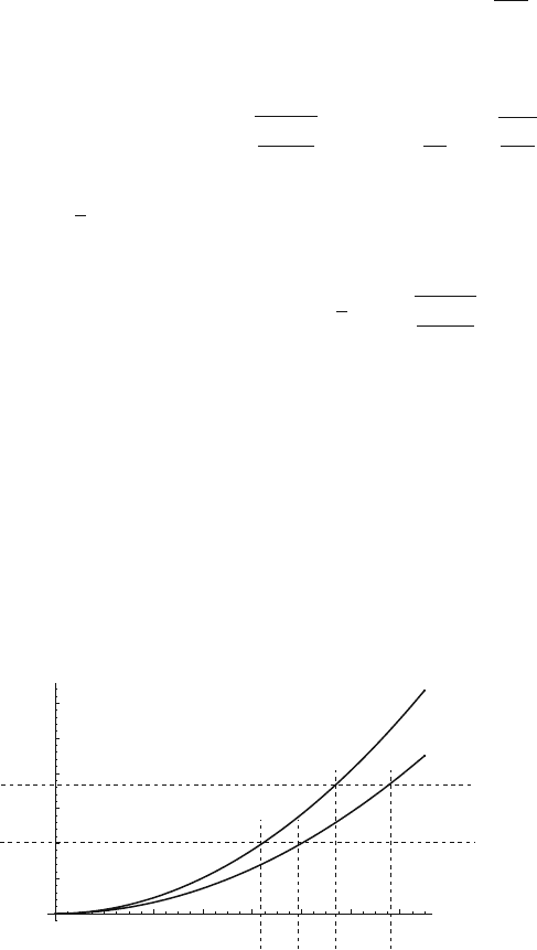
Fig. 6.52 Two signals where the electrons arrive at the wire at regular time intervals
Δ
t and 2
Δ
t,
respectively
246 6 Electronics for Drift Chambers
fluctuations and related pulse-height fluctuations. On the other hand, a broader band-
width will increase the noise and a lower threshold will increase the noise jitter
because of the parabolic shape of the signal. The compromise between these two
tendencies will define the optimum amplifier peaking time, which will again be of
the order of a few times t
0
.
Finally we note that the slope of the signal at the threshold crossing time k
s
= nk
measures the number of electrons that have contributed to the signal, and by using
this information we can improve the time resolution. The slope can, for example,
be measured by a second threshold (Fig. 6.52) or by a device that measures the
signal charge in a short time interval following the threshold crossing time. This
technique is known as amplitude and rise time compensation and allows extraction
of the optimum time information from the signal.
6.6 Three Examples of Modern Drift Chamber Electronics
In this last section we present some front-end electronics examples that are being
used in large detector systems. We discuss an amplifier for time measurement used at
rates up to 15 MHz, an amplifier for charge measurement in a cathode strip chamber,
and a front-end system for a TPC.
6.6.1 The ASDBLR Front-end Electronics
The ASDBLR (amplifier shaper discriminator baseline restorer) chip [BEN 96] is an
eight-channel front-end chip developed for readout of the ATLAS [ATL 94] transi-
tion radiation tracker [AKE 04]. The chip is implemented in a radiation hard bipolar
process. The tracker consists of almost half a million drift tubes of 4 mm diame-
ter with a 30-
μ
m-diameter anode wire. A xenon-based gas mixture at a gas gain
of ≈ 2 ×10
4
is used. The goal is a spatial resolution of better than 150
μ
matex-
treme rates of up to 15 MHz. To cope with this high rate, unipolar signal shaping
was chosen. The ASDBLR circuit is based on a front-end described in [FIS 85], and
the equivalent block diagram is equal to the one shown in Fig. 6.27 top. It consists
of a large bandwidth preamplifier with 1 ns rise time followed by a unipolar shaper
(n = 3) that provides a peaking time of t
p
= 8ns. The preamp input impedance of
R
in
= 295
Ω
is matched to the characteristic impedance of the drift tube, which rep-
resents a capacitance of C
D
≈ 12pF. A double pole-zero network cancels the signal
tail. In order to provide the baseline stability at the very high rates, the shaper is
followed by a fast (nonlinear) baseline restoration circuit using diodes. For very
small signals, the BLR acts like a CR differentiation circuit and produces a bipolar
output. As the shaper signals grow in magnitude, the exponential behaviour of the
diodes causes the undershoot to rise logarithmically with the pulse height, which
results in a unipolar signal shape. With this signal processing chain, the return to