Blum W., Riegler W., Rolandi L. Particle Detection with Drift Chambers
Подождите немного. Документ загружается.

268 7 Coordinate Measurement and Fundamental Limits of Accuracy
This is the principal limit of the coordinate measuring accuracy using pads;
θ
,
ψ
,
and
α
were defined in Fig. 7.7. In the usual case of no declustering, the values of
N
eff
for argon can be taken from Fig. 1.22.
7.3.4 Consequences of (7.33) for the Construction of TPCs
The relative size of the three terms in (7.33) depends, firstly, on the diffusion of the
electrons during their drift. In the presence of a typical longitudinal magnetic field,
the magnetic anisotropy of diffusion will make the first term the smallest one on
average, for any practical choice of b and h.
In the usual case, a pad extends over several wires, and h is much larger than b;
therefore the third term will dominate even for a small
α
. The most critical coordi-
nate measurements are those for a determination of large track momenta on tracks
with a small curvature. The pad rows should therefore be oriented at right angles to
these critical tracks, so that, for them,
α
≈ 0. For this reason, the ALEPH and the
DELPHI TPCs have circular pad rows.
With the choice of h the designer of the TPC wants to take advantage of the
fact that N(h) increases in proportion to h and N
eff
(h) approximately in proportion
to
√
h. Also, the larger the collected amount of charge on a pad the less critical is
the noise of the electronic amplifier. On the other hand the third term in (7.33) can
be kept small only within a range of
α
which becomes smaller and smaller as h
is increased. Even the modest magnetic bending of a high-momentum track may
exceed this range if h is made too large. It can be shown that the consequence is
a constant limiting relative-momentum-measuring accuracy
δ
p/p rather than one
which decreases as p is reduced.
Problems of double-track resolution are discussed in Sect. 11.7.1
7.3.5 A Measurement of the Angular Variation of the Accuracy
The second term in (7.33) can be studied in detail by measuring
σ
2
AV P
as a function
of
θ
, keeping
α
fixed at 0. This has been done by Blum et al. [BLU 86] using a small
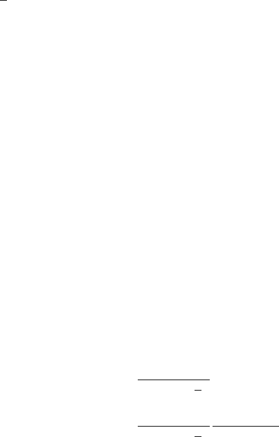
TPC with rotatable wires in a beam of 50 GeV muons. Each track had its transverse
position measured at four points using the pulse heights on the pads (see Fig. 7.11).
The pad length h was 3 cm and the wire pitch b was 4 mm. The variance was deter-
mined for every track as one half the sum of the squared residuals of the straight-line
fit. The result is
σ
2
m
, the measured variance averaged over many tracks, as a function
of the angle
θ
between the tracks and the normal to the wires. According to (7.33)
σ
2
m
should vary as
σ
2
m
=
σ
2
0
+
b
2
12N
eff
+
h,
σ
b
,
(tan
θ
−tan
ψ
)
2
cos
2
θ
=
σ
2
0
+
b
2
12N
eff
+
h,
σ
b
,
sin
2
(
θ
−
ψ
)
cos
2
ψ
, (7.34)
7.3 Accuracy in the Measurement of the Coordinate 269
Fig. 7.11 Layout of TPC with rotatable wires [BLU 86]
where
σ
2
0
contains the effects of diffusion and, perhaps, of the electronics and any
remaining contribution of the angular pad effect.
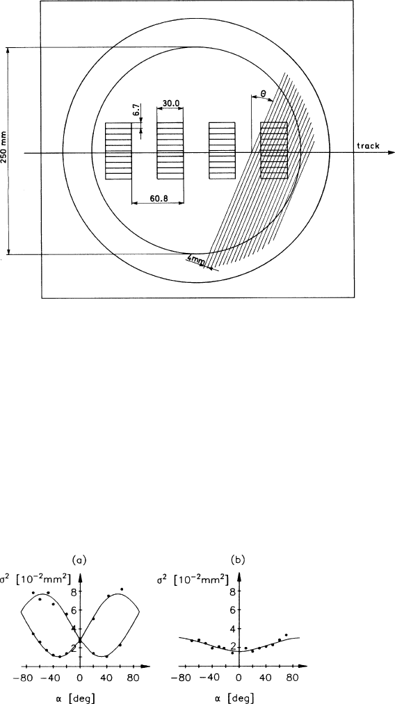
The results are depicted in Fig. 7.12a,b. The curves represent fits to (7.34) on ad-
justing the three free parameters
ψ
,
σ
0
and N
eff
(h,
σ
/b). A reversal of the magnetic
field changes the sign of
ψ
so that two curves are seen in Fig. 7.12a,ba. The values
of the fitted parameters are shown in Table 7.2.
Keeping in mind that a magnetic field of 1.5 T reduces the transverse diffu-
sion coefficient by a factor 50 (cf. Sect. 2.4.5) we expect for the mean square
width of the diffusion cloud after 4 cm of drift a value of 1.6mm
2
(B = 0) or
3.2×10
−2
mm
2
(B = 1.5T). Since on a pad length of 3 cm the number of ionization
Fig. 7.12a,b The square of the measuring accuracy
σ
determined by [BLU 86] as a function of
the track angle
θ
,(a) in a magnetic field of ±1.5T, (b) without magnetic field. The continuous
lines were calculated using (7.34) with the fitted parameters of Table 7.2
270 7 Coordinate Measurement and Fundamental Limits of Accuracy
Table 7.2 Parameters fitted to the measured accuracy
σ
2
m
according to (7.34) for two values of the
magnetic field (gas: Ar (90%)+CH
4
(10%))
B(T)
σ
2
0
(mm
2
) N
eff
+
h,
σ
b
,
ψ
(deg)
1.5 (1.08 ±0.03)10
−2
27.8±0.632.3±1.5
0 (1.58 ±0.06)10
−2
83±8 −1±2
electrons is approximately 300, the expected change in the uncertainty of the centre
is 0.5×10
−2
mm
2
, equal to the measured difference in
σ
2
0
appearing in Table 7.2.
The increase by a factor of three in the parameter N
eff
, connected with the re-
moval of the B field, is attributed to the declustering effect: as the width of the
diffusion cloud increases it becomes comparable to b, more electrons from the same
cluster arrive on different wires, and N
eff
goes up. The increase does not occur when
the tracks are produced by a laser ray rather than a particle.
The angle
ψ
of electron drift near the wire was 32
◦
at 1.5 T in gas composed of
argon (90%) and methane (10%). This value depends strongly on the gas and on the
electric field near the sense wires. The wire and field configuration employed here is
characteristic of TPCs and is described in the case studies in Sect 3.1.2. The tangent
of
ψ
is found to be roughly proportional to B.
7.4 Accuracy in the Measurement of the Coordinate
in the Drift Direction
In Sect. 7.2 we pointed out that there is a symmetry between the two situations sym-
bolized in Figs. 7.1 and 7.2, the coordinate measurement along the wire and along
the drift direction. The variances (7.5) and (7.9) of the single-electron coordinate
are basically the same if one employs the substitution rule (7.10); this holds under
the assumption that the time of arrival of the drifting electron at the entrance of the
wire region is the same, up to a constant, as that recorded by the electronics.
We must now complement this argument by the observation that for most drift
chambers this last approximation is too crude. Figure 7.2 shows that, owing to the
shape of the velocity field lines in the wire region, even electrons produced by a
track at
α
= 0 have different paths before reaching the wire: electrons collected at
the edge of the cell have to drift more than those collected in the middle.
The isochronous lines in the wire region have almost a parabolic shape and can
be approximated by
z = z
0
−a
y
2
b
,
where a is a dimensionless constant of the order of unity, which depends on the
shape of the field lines in this region. In the example of Fig. 7.2, a = 0.8.
The arrival time t on the wire of a single electron entering the wire region at y at
the time t is then
7.4 Accuracy in the Measurement of the Coordinate in the Drift Direction 271
t = t
+
1
u
z
w
+ a
y
2
b
. (7.35)
The average and variance of this last expression on the distribution (7.7) are
t =
1
u
z
0
+ a
b
12
, (7.36)
t
2
−t
2
=
1
u
2
σ
2
z
+
σ
2
y
tan
2
α
+
b
2
12
tan
2
α
+
a
2
b
2
180
, (7.37)
where the last and new term is the contribution of the drift-path variations in the
wire region.
7.4.1 Inclusion of a Magnetic Field Parallel to the Wire Direction:
the Drift E×B Effect
Drift chambers with precise measurements of the track coordinates along the drift
direction are often operated with a magnetic field perpendicular to the drift direction
and parallel to the wires. With this configuration one can obtain a precise determi-
nation of the curvature induced on the particle trajectory by the magnetic field, and
the momentum of the particle can be determined (see Chap. 8 for details).
If a magnetic field perpendicular to the drift electric field is present, the drifting
electrons have to move transverse to it. This produces an E ×B force according to
(2.6) and causes the electrons to drift under an effective angle
ψ
with respect to the
direction of the electric field. The angle
ψ
is such that tan
ψ
=
ωτ
, where
ω
is the
cyclotron frequency and
τ
is the time between two collision suitably averaged.
Electrons produced by a track at
α
= 0 do not arrive simultaneously at the en-
trance to the wire region, but their arrival positions depend linearly on y with a slope
tan
ψ
.
The variance of the arrival time of a single electron depends now on the angle
ψ
:
t
2
−t
2
=
1
u
2
σ
2
z
+
σ
2
y
tan
2
α
+
b
2
12
(tan
α
−tan
ψ
)
2
+
a
2
b
2
180
, (7.38)
where the diffusion parameter
σ
z
refers to the new drift direction, and
σ
y
to the
direction perpendicular to it and to the magnetic field. The two parameters are not
necessary equal, owing to the electric anisotropy of diffusion (cf. Sect. 2.2.5), but
for simplicity we will replace them below by a common value.
Up to now we have dealt with the drift-time variations of a single electron. When
a measurement is performed, the whole swarm arrives. There are various ways to
extract the time information. In terms of electronics, one may either employ discrim-
inators of various types in order to trigger on the first electrons, or on the centroid
of the pulse or on some other value based on a threshold-crossing time. Or one may
apply a very fast sampling technique in order to obtain a numerical representation of

272 7 Coordinate Measurement and Fundamental Limits of Accuracy
the pulse shape, which may be used to derive a suitable estimator. We discuss here
two estimators of the arrival time of the swarm: the average and the Mth electron,
assuming for simplicity
ψ
= 0.
7.4.2 Average Arrival Time of Many Electrons
When we average over the arrival times of all the electrons, the statistical reduction
of the different terms of (7.38) is not the same because of the correlation between
electrons produced in the same cluster. Following the lines of Sect. 7.2 we can write
the variance of the average arrival time as
σ
2
TAV
=
1
u
2
1
N
σ
2
cos
2
α
+
1
N
eff
b
2
12
tan
2
α
+
a
2
b
2
180
, (7.39)
where N represents the total ionization collected by the wire, and N
eff
is the effective
number of independent electrons.
The contribution of the drift-path variation of the variance of the average is al-
ways present, even for tracks in good geometry (
α
= 0) and close to the wire
(
σ
≈0). It is quite large and increases with b more than linearly, since N
eff
increases
with the track length more slowly than in proportion.
Obviously the average over all arrival times fluctuates so badly because of the
late-arriving electrons, those that have to take the longest path when they approach
the wire. If one derives the time signal from the few electrons that arrive first, the
latecomers do not contribute. In fact, a discriminator with a low threshold will do
this automatically.
7.4.3 Arrival Time of the Mth Electron
Let the time signal be defined by the moment that the Mth electron arrives. Here M
can either be a fixed number (this is the case when a fixed-threshold discriminator
is used) or a given fraction of the total number of electrons contributing (this is the
case of a constant-fraction discriminator).
The probability p(t) of one electron arriving before the time t is calculable using
(7.7) and (7.35):
p(t)=
t
−∞
f (
τ
)d
τ
+∞
−∞
f (
τ
)d
τ
, (7.40)
where
f (
τ
)d
τ
=
+b/2
−b/2
dyf
z
(
τ
−(z
w
+ ay
2
/b)/u,y)d
τ
. (7.41)
Next we have to write out the probability R(t) that the Mth electron out of a
group of N arrives in the interval dt. It is equal to the probability that any one of

7.4 Accuracy in the Measurement of the Coordinate in the Drift Direction 273
the N electrons arrives precisely in dt (equal to N (dp/dt)orN dp) multiplied by the
probability that any of (M −1) out of the (N −1) remaining ones arrives before t
and the rest after t + dt:
R(t)dt = N
N −1
M −1
p
M−1
(1−p)
N−M
dp
dt
dt
= M
N
M
p
M−1
(1−p)
N−M
dp = P(p)dp. (7.42)
In the last expression we have defined a probability density P(p) for the variable p.
It is easy to show that
+∞
−∞
R(t)dt =
1
0
P(p)dp = 1 .
Here and in the following steps we make use of the well-known expression for
the definite integral
1
0
x
k
(1−x)
j
dx =
j!k!
( j + k + 1)!
.
The variance of the arrival time of the Mth electron is given by
σ
2
TM
= t
2
−t
2
,
with
t
2
=
+∞
−∞
t
2
R(t)dt =
1
0
t
2
(p)P(p)dp
and
t =
+∞
−∞
tR(t)dt =
1
0
t(p)P(p)dp . (7.43)
The function t(p) is obtained by inverting (7.40).
We consider now separately the two contributions of the difference of the drift
paths and of the diffusion and study the particular case of a track perpendicular to
the drift velocity direction (
α
= 0).
7.4.4 Variance of the Arrival Time of the Mth Electron:
Contribution of the Drift-Path Variations
In order to study the effect of the drift-path variation alone we go to the limit
σ
y
→ 0,
σ
t
→ 0 of (7.41) at
α
= 0, and obtain
274 7 Coordinate Measurement and Fundamental Limits of Accuracy
f (t)dt =
u
R
1
a
b
(tu−z
0
)
dt, 0 ≤ (tu−z
0
) ≤
ab
4
(7.44)
and f (t)=0 outside of this time interval. Using this expression we can evaluate
p(t) from (7.40) and invert it:
t(p)=
1
u
ab
4
p
2
+ z
0
. (7.45)
Now we compute the integrals (7.43) and use this expression for t(p):
σ
2
TPM
=
ab
4u
2
M(M + 1)
(N + 1)(N + 2)
(M + 2)(M + 3)
(N + 3)(N + 4)
−
M(M + 1)
(N + 1)(N + 2)
. (7.46)
This is the variance in the arrival time of the Mth electron among N independent
ones when only the drift-path variation is taken into account.
If we want to apply this formula to a practical case we have to use for N the
number of clusters, and we realize that because of the cluster-size fluctuations it
describes correctly only the case M = 1, since the threshold can only be set at a
certain number of electrons and not of clusters.
In order to take into account the cluster-size fluctuations we have to use a Monte
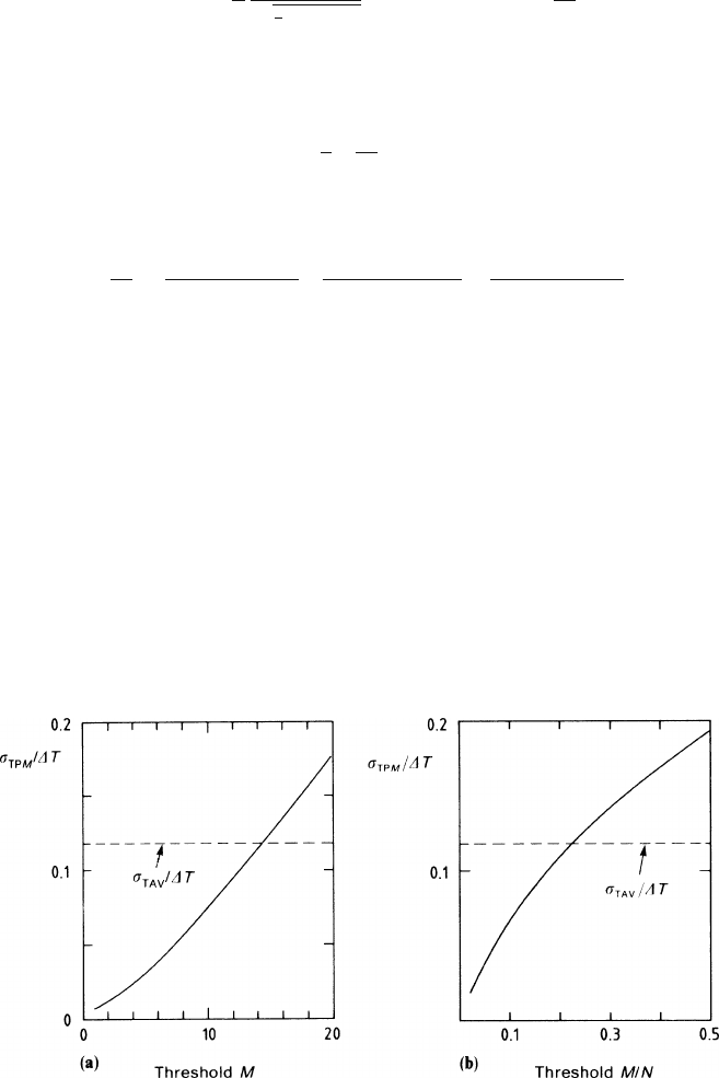
Carlo program. Figure 7.13a,b shows the result of a simulation of the distribution of
the arrival times, assuming the conditions valid for 1 cm of argon gas at NTP (and
27 clusters/cm). In both parts of the figure the r.m.s. of the arrival time is normalized
to the width of the collection time interval:
Δ
T = ab/4u .
Fig. 7.13a,b R.m.s. variation of the arrival time of the Mth electron in 1 cm of argon, caused by
differences in drift-path length, (a) as a function of M,(b)whenM is a fixed fraction of the total
number of electrons N. The r.m.s. of the average time is also shown. (See text for explanations.)
7.4 Accuracy in the Measurement of the Coordinate in the Drift Direction 275
Also visible is the r.m.s. of the average (7.39), evaluated for
α
= 0,
σ
= 0, N
eff
= 6
and normalized to the same quantity. We observe that the limit of the accuracy due
to the drift-path variation can be made very small by lowering the threshold. For
example,
σ
TM
comes down to 30% of
σ
TAV
when triggering on a value of M equal
to 5% of N. But by gaining on the drift-path variations, one loses on the diffusion
term.
7.4.5 Variance of the Arrival Time of the Mth Electron:
Contribution of the Diffusion
Next we study the contribution of diffusion. The probability density f (t) of (7.41)
with a = 0 and
α
= 0 takes the form
f (t)dt =
b
R
exp
−
(
t−
z
0
u
)
2
2
σ
2
t
√
2
πσ
t
dt , (7.47)
and the function p(t) of (7.40) is the function E:
p(t)=E
t −z
0
/u
σ
t
=
t−z
0
/u
σ
t
−∞
dq
exp(−q
2
/2)
√
2
π
. (7.48)
To compute the variance of the arrival time of the Mth electron we should solve
the integrals (7.43) using the function t(p) defined by the inverse of (7.40).
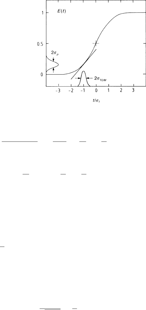
Since we cannot invert the expression (7.48) analytically, we linearize it in the
vicinity of the average value of the function P(p) of (7.42). This procedure is justi-
fied by the fact that the variance of the function P(p) is small when M is small and N
large. It is illustrated in Fig. 7.14. The variance of the arrival time is the variance of
p on the probability distribution P(p) projected onto the t axis using the derivative
dt
dp
=
σ
t
dq
dE(q)
=
σ
t
√
2
π
exp
+
q
2
2
,
evaluated at q defined by p = E(q).
The variance of p is given by
p
2
=
1
0
p
2
P(p)dp =
M
N + 1
and
p
2
=
1
0
p
2
P(p)dp =
M(M + 1)
(N + 1)(N + 2)
,
276 7 Coordinate Measurement and Fundamental Limits of Accuracy
Fig. 7.14 Illustration of
(7.50): the variance of p is
projected onto the time axis
using the tangent to the error
function erf(t) in order to
obtain
σ
TDM
from which we obtain
p
2
−p
2
=
M
(N + 1)(N + 2)
1−
M
N + 1
≈
M
N
2
1−
M
N
. (7.49)
Projecting now this variance onto the time axis (see Fig. 7.14) we obtain
σ
2
TDM
≈
σ
2
t
N
2
π
exp(q
2
)
M
N
1−
M
N
, (7.50)
where q is the normalized average arrival time, given by the condition that the
corresponding integral probability p takes on the value M/(N + 1), or in good ap-
proximation, M/N. In other words, q is given by the inverse of the function E at
its argument M/N :
q = E
−1
(M/N) . (7.51)
Expression (7.50) with (7.51) represents the answer to the question how much the
arrival time of the Mth electron fluctuates when each single electron has a Gaussian
distribution with a width
σ
t
;
σ
TDM
goes down with the total number N of electrons
and is equal to
σ
t
/
√
N times a factor which depends only on M/N. The factor de-
scribes the loss of accuracy when the arrival-time measurement is based on the Mth
electron rather than on the average of all N. (The variance
σ
2
TAV
of the average ar-
rival time caused by diffusion alone was
σ
2
t
/N as implied by (7.39).) The loss factor
is plotted in Fig. 7.15 and is seen to be always larger than 1. For example the loss is
a factor 2 if one triggers on the first 5% of the swarm.
An often-quoted formula according to which
σ
TDM
=
σ
t
√
2logN
∞
∑
r=M
1
r
2
(7.52)
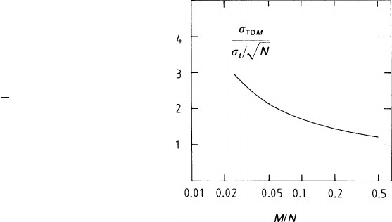
7.5 Accuracy Limitation Owing to Wire Vibrations 277
Fig. 7.15 Errors of time
measurement caused by
diffusion: r.m.s. variation
σ
TDM
of the arrival time of
the Mth electron, in units of
the r.m.s. variation of the
average arrival time of N
electrons,
σ
t
/
√
N, plotted as
a function of M/N
instead of (7.50) has been discussed by Cramer [CRA 51]. The right-hand side of
(7.52) is the first term of a power series in 1/logN. It turns out that for M = 1 (7.52)
is more accurate than (7.50), but it cannot reproduce the variation of
σ
TDM
with M.
We conclude this section with a comment on the various ways to estimate the
time of arrival of the electron swarm. It is clear from the previous pages that this is
a question of the relative importance of the two main contributions to the measure-
ment accuracy. Where the drift-path variations are relatively large, one gains a lot
by triggering on a low threshold. Where the diffusion is relatively large, one gains,
but not so much, by using the average. The contribution from the angular effect and
from the effect of the drift-path variations quickly increase as the angle
α
increases.
Since the diffusion increases with the drift length, the relative importance of the two
contributions changes through their dependence on
σ
t
and N
eff
, and the best estima-
tor is a function of the drift length. Depending on how far one wants to go in the
optimization, the fast sampling technique offers the greatest freedom.
7.5 Accuracy Limitation Owing to Wire Vibrations
Up to this point we have had two phenomena which, in functioning together, pro-
duce fundamental limitations on the accuracy of coordinate measurement: diffusion
and ionization fluctuation. As we have seen in this chapter, these limitations are fun-
damental in the sense that they are inherent in the measuring process and cannot be
overcome by removing technical imperfections.
After the appearance of the first edition of this book, a new phenomenon was de-
scribed which also limits the accuracy of coordinate measurement in a fundamental
way: wire vibrations caused by the avalanches on the sense wire [BOY 95]. Every
avalanche exerts a repulsive force onto the wire as long as the positive ions are on
their way to the cathode. Upon their arrival at the cathode they have conveyed a
tiny bit of momentum to the wire. In an environment of heavy background radiation