Blum W., Riegler W., Rolandi L. Particle Detection with Drift Chambers
Подождите немного. Документ загружается.

258 7 Coordinate Measurement and Fundamental Limits of Accuracy
diffusion are collected by the wire:
M
∑
j=1
n
j
= N . (7.11)
In general not all the electrons produced in the same cluster are collected by the
wire because of the random diffusion along the drift path.
The variance of X
AV
is by definition
σ
2
X
AV
=
-
X
2
AV
.
−
X
AV
2
, (7.12)
where the average is taken over the probability distribution f
x
:
X
AV
=
∑
x
i
N
=
b/2
−b/2
dy
+∞
−∞
xf
x
(x,y)dx = x
0
(7.13)
and
-
X
2
AV
.
=
1
N
2
∑
ij
x
i
x
j
. (7.14)
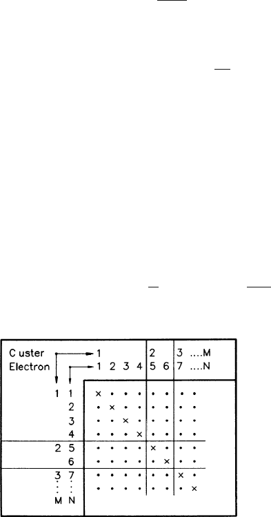
The sum in the last equation contains three different kinds of terms; refer to
Table 7.1 for a graphical representation. When i = j then x
i
x
j
= x
2
. There are
N terms of this kind; they are marked by crosses in the table. When i = j and the
electrons do not belong to the same cluster, then x
i
x
j
= x
2
, because two different
ionization processes are not correlated. There are N
2
−
∑
n
2
j
terms of this kind, they
are represented by the dots in the rectangular boxes of the table. When i = j and the
electrons do belong to the same cluster (the dots in the square boxes), then x
i
and x
j
are correlated. We define the average x
i
x
j
= xx. There are
∑
n
2
j
−N terms of this
kind.
Using (7.12–7.14) one finds that the variance is equal to
σ
2
X
AV
=
1
N
(x
2
−xx)+
∑
n
2
j
N
2
(xx−x
2
) . (7.15)
Table 7.1 Classification of the pairs of all electrons from a track that were collected on one wire
7.2 Basic Formulae for a Single Wire 259
In the absence of diffusion, xxis equal to x
2
and the first term of (7.15) is zero,
so we obtain the result derived in Sect. 1.2, where the quantity
∑
n
2
j
/N
2
was defined
as 1/N
eff
. If all the clusters consisted of one electron, the term
∑
n
2
j
/N
2
there became
equal to 1/N and we obtained the standard formula of the variance of the mean.
We may therefore distinguish the following limiting cases of (7.15):
• Limit of no diffusion, using (7.5):
σ
2
X
AV
→
1
N
eff
(x
2
−x
2
)=
1
N
eff
b
2
12
tan
2
θ
. (7.16)
• Limit of no clustering, using (7.5) and
σ
x
=
σ
y
=
σ
:
σ
2
X
AV
→
1
N
(x
2
−x
2
)=
1
N
σ
2
cos
2
θ
+
b
2
12
tan
2
θ
. (7.17)
• Limit
θ
= 0, in the presence of clustering:
σ
2
X
AV
→
σ
N
. (7.18)
In (7.16–7.18), N
eff
is the effective number and N is the total number of elec-
trons on the track segment delimited by the cell width; their values are
θ
-dependent
through the length of the track segment.
An analytical expression of the covariance xx in (7.15) is derived under certain
assumptions in the appendix to this chapter, resulting in formula (7.81) for
σ
2
X
AV
.
This can be rewritten in the form
σ
2
X
AV
→
1
N
σ
2
cos
2
θ
+
1
N
eff
b
2
12
tan
2
θ
. (7.19)
where the quantities N
and N
eff
depend on
θ
as well as on
σ
and b.
Let us first deal with the term proportional to (b
2
/12)tan
2
θ
. We may regard N
eff
as the effective number of electrons that would cause the same fluctuation as the
combined action of ionization plus diffusion, thus extending the original meaning
of N
eff
defined in Sect. 1.2 and used in (7.16).
The quantity N
eff
, for which an analytic expression is given in the
appendix to this chapter, can also be calculated with a numerical simulation of the
ionization and diffusion process. In order to compute it as a function of the diffusion
parameter
σ
we evaluate the variance V
AV
of the average of the coordinates along
the track direction of those electrons that, after diffusion
σ
along the track direction,
are contained in a track segment of length l. We write
1
N
eff
1
N
eff
(
σ
)
=
l
2
12
1
V
AV
(
σ
)
. (7.20)
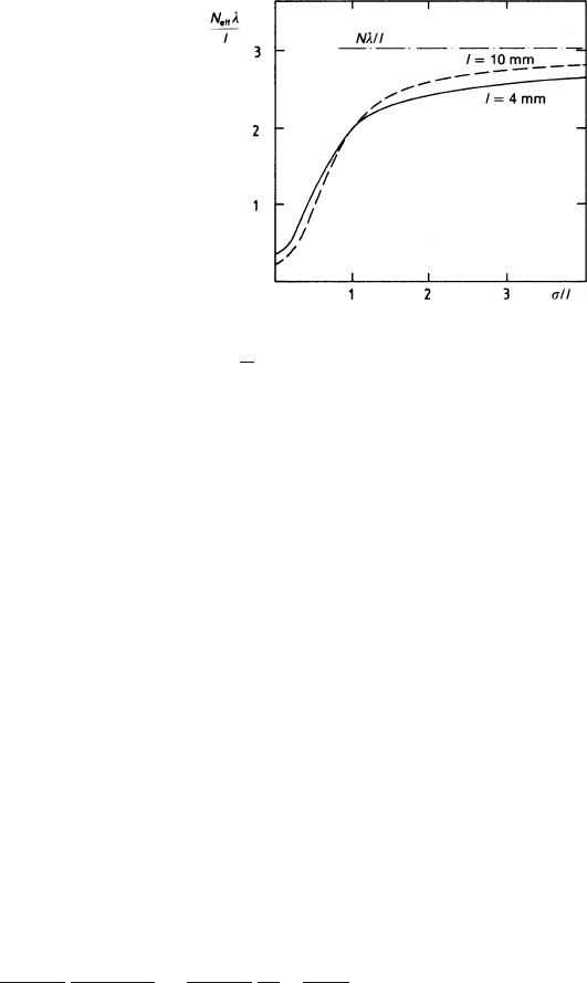
Figure 7.3 shows how N
eff
(
σ
) varies with diffusion. We have plotted on the ver-
tical axis the quantity
260 7 Coordinate Measurement and Fundamental Limits of Accuracy
Fig. 7.3 Declustering
through diffusion: effective
number of electrons divided
by the total number of
clusters, as a function of
σ
/l,
for two values of l.Inthe
Monte Carlo calculation the
cluster-size distribution of
Fig. 1.7 and a value of
1/
λ
= 2.7 clusters/mm were
used
N
eff
(
σ
)
λ
l
,
where the ratio
λ
/l is equal to the average number of clusters on the track segment
l (
λ
was defined in Sect. 1.1.1 as the mean distance between two clusters). There-
fore N
eff
(
σ
)
λ
/l is the ratio of the effective number of electrons over the number of
clusters in the track length l.
On the horizontal scale we have the diffusion expressed in units of the length
of the track segment
σ
/l. This is suggested by (7.81) and is a very natural choice
because the change of N
eff
(
σ
) is caused by electrons that have diffused so much
that they cross over from one track segment to the neighbouring one, thus breaking
the cluster correlation. It can therefore be expected that N
eff
(
σ
) goes up when
σ
ex-
ceeds some distance comparable to the length of the track segment, i.e. the distance
between the wires. And this is in fact what we see.
The curves in Fig. 7.3 where computed using the argon cluster-size distribution
of Fig. 1.7. At zero diffusion N
eff
(0) is only 0.3(l = 0.4cm) or 0.2 (l = 1cm) of
the number of clusters. We know from Fig. 1.19 that this number must go down
with increasing l. Now we switch on the diffusion, and before
σ
has reached half
the length l of the segment, N
eff
(
σ
) is as large as the number of clusters. For very
large
σ
/l all the clustering is destroyed by the diffusion, and N
eff
(
σ
) approaches the
total number N of electrons. The increase of N
eff
(
σ
) with
σ
/l was first observed in
a TPC and termed declustering through diffusion [BLU 86].
We notice that the wire angular term in (7.19) can be written in the following
way:
1
N
eff
(
σ
)
(btan
θ
)
2
12
=
1
N
eff
(
σ
)
1
12
b
cos
θ
2
sin
2
θ
. (7.21)
It represents the variance of the average of the position along the track direction of
the electrons sampled by the wire, projected onto the wire direction. The first term
is the variance of a flat distribution of width b/cos
θ
, which is the length of the track
segment sampled by the wire. The factor sin
2
θ
projects this variance onto the wire
direction.
After this discussion of N
eff
as contained in the second term of (7.19), we deal
now with the first term. The simple form into which we have cast the terms directly

7.3 Accuracy in the Measurement of the Coordinate 261
proportional to
σ
2
(cf. (7.81)) hides the complications in the symbol N
. Although it
is true that in the limiting cases of (7.17) and (7.18) N
is exactly equal to N, the total
number of electrons on the track segment delimited by the cell width, N
changes
as a function of
θ
,
σ
and b so as to make the variance
σ
2
X
AV
larger. The physical
cause of this is the rare larger clusters outside the cell that send some electrons via
diffusion to the edge of the cell, and more so when
θ
is large. We have two reasons
not to go into these details here. When we omit the primes in (7.19) the omissions
amount to less than 25% in the quantity
σ
X
AV
(except in extreme cases). The omitted
parts, which pull measurements to one side in our cell, have a tendency to pull the
corresponding measurement in the neighbouring cell to the opposite side. Therefore
it is better to leave them out when combining several cells. The contributions of
several wires are discussed in Sects. 7.3 and 7.4.
In conclusion we simplify (7.19) to read
σ
2
X
AV
=
1
N
σ
2
cos
2
θ
+
1
N
eff
b
2
12
tan
2
θ
. (7.22)
It represents the square of the accuracy with which a track coordinate X
AV
(7.10)
can be measured along a single wire in the absence of a magnetic field.
7.3 Accuracy in the Measurement of the Coordinate
in or near the Wire Direction
7.3.1 Inclusion of a Magnetic Field Perpendicular to the Wire
Direction: the Wire E ×
×
× B Effect
Drift chambers with precise measurements of the track coordinates along the wire
direction are often operated with a magnetic field perpendicular to the direction of
the wires. With this configuration one can obtain a precise determination of the cur-
vature induced on the particle trajectory by the magnetic field, and the momentum
of the particle can be determined (see Chap. 8 for details).
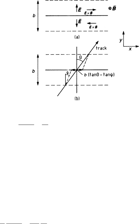
The presence of a magnetic field perpendicular to the wire direction modifies the
angular wire term of the variance of the arrival position of the electrons (7.5). It
becomes asymmetric and, on average, larger because the track segment is projected
onto the wire in a more complicated way. The electrons that after their drift are
collected in the cylindrical field of the wire have to move transverse to the magnetic
field (Fig. 7.4). This produces an E ×B force according to (2.6) and causes the
electrons to drift under an effective angle
ψ
toward the wire. The angle
ψ
is such
that tan
ψ
=
ωτ
, where
ω
is the cyclotron frequency and
τ
is the time between two
electron collisions suitably averaged. Details have been treated in Sect. 2.1.
The arrival position x
w
of an electron entering the region close to the wire
with coordinates x and y is x
w
= x −ytan
ψ
; the variance of x
w
on the frequency
distribution (7.3) is
262 7 Coordinate Measurement and Fundamental Limits of Accuracy
Fig. 7.4 (a) Directions of the
electric and magnetic fields in
the region close to the sense
wire. The magnetic field
points into the page. (b)
Direction of the drift velocity
of the electrons in this region
projected onto the x–y plane
x
2
w
−x
w
2
=
σ
2
cos
2
θ
+
b
2
12
(tan
θ
−tan
ψ
)
2
. (7.23)
The electrons produced by a track at
θ
= 0 are spread over a region btan
ψ
, and
those of a track at an arbitrary angle are smeared over a distance b(tan
θ
−tan
ψ
).
The width of the charge distribution on the wire has a minimum at
θ
=
ψ
and not at
θ
= 0.
This effect was discovered with the TRIUMF-TPC [HAR 84] and is typically the
most important limitation of the measuring accuracy in all TPC-like detectors using
a gas with high values of
ωτ
. In the TRIUMF-TPC the angle
ψ
was 29
◦
, and 32
◦
in
the ALEPH TPC in standard running conditions. The broadening of the avalanche
width has been systematically studied in [BLU 86].
Using (7.23) we can rewrite (7.22) to include this effect:
σ
2
X
AV
=
1
N
σ
2
cos
2
θ
+
1
N
eff
b
2
12
(tan
θ
−tan
ψ
)
2
. (7.24)
Equation (7.24) is the general expression for the accuracy
σ
X
AV
with which a
track segment can be measured on one wire along the wire direction. Summa-
rizing our findings up to here, we see that this accuracy depends on the pro-
jected angle
θ
the track has with respect to the normal to the wire direction as
well as on the angle
ψ
of the wire E ×B effect. N
eff
is roughly 6 for 1 cm of
argon NTP and is more accurately obtained in Figs. 7.3 and 1.19. The diffu-
sion term is characterized by the width
σ
of the single-electron diffusion trans-
verse to the drift and the total number N of electrons, typically 100/cm in argon
NTP.
The size and relative importance of the two terms in (7.24) depend on the electron
drift length L, because
σ
2
is proportional to L and N
eff
depends on L through the
declustering effect (Fig. 7.3). Also the angle
θ
has some influence on N and N
eff
as
the length of the track segment varies with
θ
. If one wants to be more specific, one
has to take into account the details of a particular chamber.
7.3 Accuracy in the Measurement of the Coordinate 263
7.3.2 Case Study of the Explicit Dependence of the Resolution
on L and θ
Writing (7.24) in the form
σ
2
X
AV
=
1
n
0
C
2
L
bcos
θ
+
b
12
(tan
θ
tan
ψ
)
2
cos
θ
g(L)
(7.25)
we have introduced the L dependence of the diffusion and of N
eff
:
σ
2
= C
2
L , (7.26)
N
eff
= Ng(L) , (7.27)
as well as the
θ
dependence of N:
N = n
0
b/cos
θ
. (7.28)
Here n
0
is the number of collected electrons per unit track length. (We recall
that g(L) is not a universal function but depends to some extent on N, b
and
θ
.)
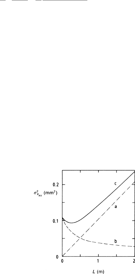
Figure 7.5a-c shows
σ
2
X
AV
calculated as a function of L at
θ
= 0forC
2
= 3.4 ×
10
−3
mm,
ψ
= 32
◦
(corresponding to a gas mixture of 80% argon and 20% methane
in a field of 0.85 T), b = 4mm, n
0
= 8.1electrons/mm. We notice that the resolu-
tion goes through a shallow minimum at small L and is dominated by diffusion at
large L.
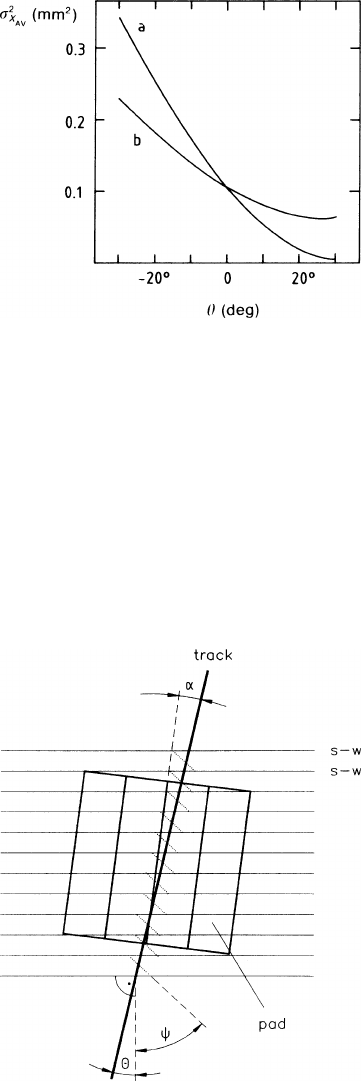
Figure 7.6 shows
σ
2
X
AV
as a function of the angle
θ
for two different values of L
and for the same choice of the other parameters.
Fig. 7.5a-c Variance of the
average arrival position as a
function of the drift length at
θ
= 0 – the special case
described in the text. (a)
Contribution of the diffusion;
(b) contribution of the
angular wire effect; (c) sum
of the two
264 7 Coordinate Measurement and Fundamental Limits of Accuracy
Fig. 7.6 Variance of the
average arrival position of the
electrons as a function of the
angle
θ
– the special case
described in the text.
(a)L = 0, (b)L = 50cm
7.3.3 The General Situation – Contributions of Several Wires,
and the Angular Pad Effect
The most general situation is the one where the coordinate direction along the pad
row is inclined with respect to the wire direction, and several wires are located op-
posite the same cathode strips, as seen in Fig. 7.7. Apart from
θ
, the angle between
the track and the wire normal, and
ψ
, the effective angle of approach caused by the
wire E ×B effect, we also have
α
, the angle between the normal to the direction of
the pad row and the track; all angles are measured in the wire plane. The angles
θ
and
α
are the same when the pad row follows the wire direction.
Fig. 7.7 Scheme of a
chamber with cathode-strip
readout. The bold lines
indicate the arrival positions
of the electrons on the wire;
the dotted lines indicate the
direction of the drift velocity
in the region close to the
sense wires
7.3 Accuracy in the Measurement of the Coordinate 265
The signals induced in a cathode strip are from k wires, where
k = pad length h/wire pitch b.
These signals are added in the measuring process. We want to compute the achiev-
able accuracy. As the situation is quite complicated we wish to start with a simple
case. The basic statistical relation will be derived for the special geometry given by
α
= 0,
θ
= 0; also we will assume
σ
= 0. Later on we will generalize our findings
step by step.
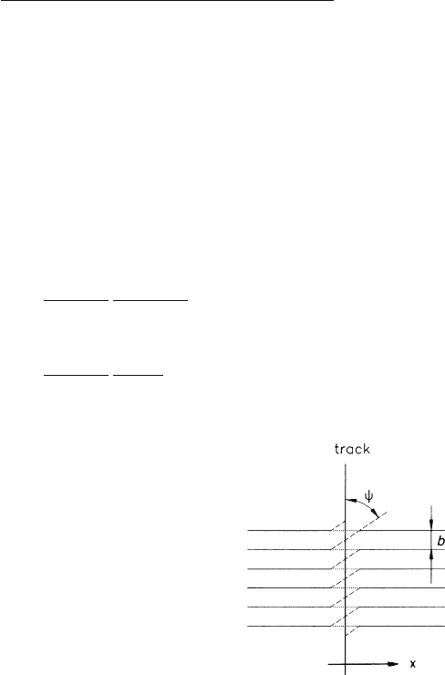
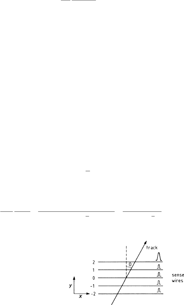
The simplified geometry is sketched in Fig. 7.8. The ionization clusters along the
track are redistributed onto the sense wires, where they occupy sections of length
btan
ψ
. The situation is quite similar to the one in Sect. 1.2.6, where we treated the
problem of charge localization along a track. The coordinate to be determined by
the pads in one measurement is
X
AV P
=
∑
m
1
i=1
x
i
n
i
+
∑
m
2
i=m
1
+1
x
i
n
i
+ ...+
∑
m
k
i=m
k−1
+1
x
i
n
i
+
∑
m
k
i=1
n
i
,
2
, (7.29)
where each x
i
is the position of a cluster with n
i
electrons; there are m
1
clusters
on the first, and m
j
−m
j−1
on the jth sense wire ( j = 1,...,k). Averaging over the
positions x
i
– which are distributed between −(b/2)tan
ψ
and +(b/2)tan
ψ
–we
find for the average and the variance
X
AV P
= 0
and
σ
2
AV P
=
-
X
2
AV P
.
−X
AV P
2
=
b
2
tan
2
ψ
12
∑
m
k
i=1
n
2
i
+
∑
m
k
i=1
n
i
,
2
(7.30)
σ
2
AV P
=
b
2
tan
2
ψ
12
1
N
eff
(h)
(
α
=
θ
=
σ
= 0) .
Fig. 7.8 Track and sense
wires for (7.30)
266 7 Coordinate Measurement and Fundamental Limits of Accuracy
Here we have denoted by 1/N
eff
(h) the statistical factor which is equal to the sum
of the squared cluster size divided by the square of the summed cluster sizes, taken
over all the clusters on the piece of track that is delimited by the pad length h. Let us
repeat (cf. Sect. 1.2.9 that the effective number N
eff
is a measure of fluctuation which
is smaller than the number of clusters because of the fluctuations of the cluster size.
It is not proportional to h; for argon it scales according to Fig. 1.22. Comparing
N
eff
(b), the corresponding number that belongs to a wire cell, we have for that case
N
eff
(h) ∼N
eff
(b)(h/b)
0.54
.
For this reason the achievable accuracy of pads does not improve with the square
root but (for argon) more with the fourth root of the pad length.
In the next step we let
θ
and
σ
be different from zero, but keep
σ
b and
α
= 0.
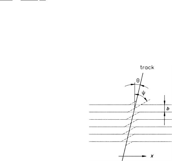
The geometry is sketched in Fig. 7.9. The angle
θ
the track makes with the wire nor-
mal has two consequences: it changes the length on the wire occupied by charges,
from b tan
ψ
to b(tan
ψ
−tan
θ
), and it introduces the projection factor cos
θ
be-
tween this length and the coordinate direction. The diffusion, finally, contributes to
the variance the same term as in (7.22) but with two changes. Firstly, the projection
factor onto the coordinate direction is 1 in the present case. Secondly, N now repre-
sents the total number of electrons from the track segment delimited by h; we write
N(h), which is of course proportional to h. The variance of X
AV P
therefore assumes
the form
σ
2
X
AV P
=
σ
2
N(h)
+
1
N
eff
(h)
b
2
12
(tan
ψ
−tan
θ
)
2
cos
2
θ
(
α
= 0,
σ
b). (7.31)
Next we let
α
assume a non-zero value. This has the consequence that the two
projection factors must be referred to the new coordinate direction, that is the dif-
fusion term receives in its denominator the factor cos
2
α
, and the projection factor
of the angular term changes into cos
2
(
θ
−
α
). The variance (7.31) of X
AV P
receives
another contribution, which describes the fluctuation of the position of the centre of
Fig. 7.9 Track and sense
wires for (7.31)
7.3 Accuracy in the Measurement of the Coordinate 267
charge along the track segment, because a non-zero angle
α
projects this fluctuation
onto the coordinate direction. The size of this term is proportional to the squared
length of the pad,
1
N
eff
(htan
α
)
2
12
. (7.32)
This is the angular pad effect. We recognize the similarity with the corresponding
angular wire term in (7.22); in (7.32) the fluctuation is controlled by the effective
number of electrons on the track segment defined by the pad.
This contribution to the variance can be suppressed if the pulse height on the
relevant wires is recorded, because one way of looking at this fluctuation is that it
is caused by the differences in the charge deposited on the wires (see Fig. 7.10).
It has been demonstrated in practice [AME 83, BAR 82], that the measured track
position can be corrected using the wire pulse heights, leaving only a small residual
error.
Finally we have to lift the restriction that
σ
2
should be small compared to b
2
.
In order for declustering to occur, the diffusion must reach the value of a length
parameter which reorganizes the charges in such a way that the cluster correlation is
broken, thus making N
eff
larger. For the angular terms in (7.22) and (7.24) it was b
that set the scale whereas in the angular pad term (7.32) it is h that sets the scale. (It
is irrelevant on which wire the charge is collected – only new charges from outside
the pad region improve the cluster statistics.)
Although the declustering effect often does not play a decisive role in practical
drift chambers – because the diffusion is not large enough – we want to be specific
in distinguishing the respective scales of the declustering.
For this purpose we denote by
N
eff
h,
σ
b
the effective number of electrons on the track segment delimited by h and declus-
tered by diffusion on the scale b. In this sense the variance of X
AV P
takes the form
σ
2
AV P
=
1
N(h)
σ
2
cos
2
α
+
b
2
(tan
θ
−tan
ψ
)
2
cos
2
(
θ
−
α
)
12N
eff
+
h,
σ
b
,
+
(h
2
−b
2
)tan
2
α
12N
eff
+
h,
σ
h
,
. (7.33)
Fig. 7.10 Displacement of
the measured coordinate
owing to charge fluctuations
between the sense wires that
contribute to a pad signal.
The large pulse height
collected by wire 2 moves the
centroid towards positive x