Blum W., Riegler W., Rolandi L. Particle Detection with Drift Chambers
Подождите немного. Документ загружается.

6.3 Noise and Optimum Filters 227
20 40 60 80 100
500
1000
1500
2000
2500
3000
3500
4000
ENC (electrons)
20 40 60 80 100
t
p
(ns)
500
1000
1500
2000
2500
3000
3500
4000
ENC (electrons)
t
p
(ns)
S
1
2
1
S
2
3
3
(a)
(b)
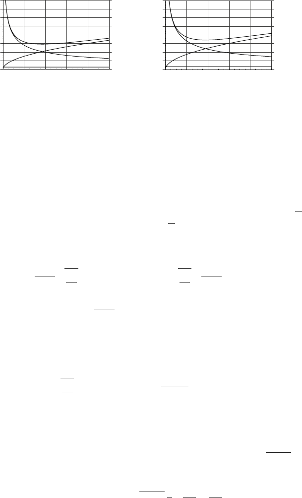
Fig. 6.39 Equivalent noise charge (ENC) as a function of the peaking time, calculated from
Eq. (6.115). The three noise components are plotted separately, using typical values for the dif-
ferent noise sources: parallel noise (R
p
= 10k
Ω
) curves 1, series noise (R
s
= 150
Ω
)curves2,1/ f
noise curves 3. The resulting total noise curves S exhibit a shallow minimum. (a) unipolar shaping,
(b) bipolar shaping, both with n = 4
The three components of the ENC for the cathode channel are due to the parallel
white noise, series white noise, and the 1/ f noise of the amplifier. The noise r.m.s.
for the bipolar and the unipolar shaper as a function of amplifier peaking time is
shown in Fig. 6.39. The three components of the noise exhibit a very distinct de-
pendence on the amplifier peaking time. The parallel noise is proportional to
√
t
p
,
whereas the series noise is proportional to 1/
√
t
p
. The contribution from the 1/ f
noise is independent of the amplifier peaking time. The noise
σ
v
shows a minimum
at the peaking time t
opt
given by
t
opt
= C
D
R
s
R
p
#
K
s
K
p
ENC
2
opt
= 8kTC
D
#
R
s
R
p
K
s
K
p
+ BC
2
D
K
f
. (6.117)
The time constant
τ
c
= C
D
R
s
R
p
is the so-called noise corner time constant,so
the optimum peaking time is of the same order as
τ
c
. In the following we neglect
the small 1/ f component of the noise. For estimation of the order of magnitude for
t
opt
and ENC
opt
we take an example where R
p
= 10k
Ω
and R
s
= 100
Ω
at room
temperature T = 295 K, which results in
t
opt
[ns]=C
D
[pF]
#
K
s
K
p
ENC
opt
= 350
C
D
[pF](K
s
K
p
)
1/4
electrons. (6.118)
Assuming a detector capacitance of C
d
= 20–50 pF and that K
p
and K
s
are of the
order of unity, we find optimum peaking times in the range from 20–50 ns and ENC
values between 1500 and 1800 electrons. We will see later that the minimum possi-
ble ENC for any kind of shaping function is given by ENC
2
min
= 4kTC
s
R
s
/R
p
,so
we can rewrite the expression for the ENC as
ENC
2
(t
p
)=ENC
2
min
4K
p
K
s
1
2
t
p
t
opt
+
t
opt
t
p
. (6.119)
228 6 Electronics for Drift Chambers
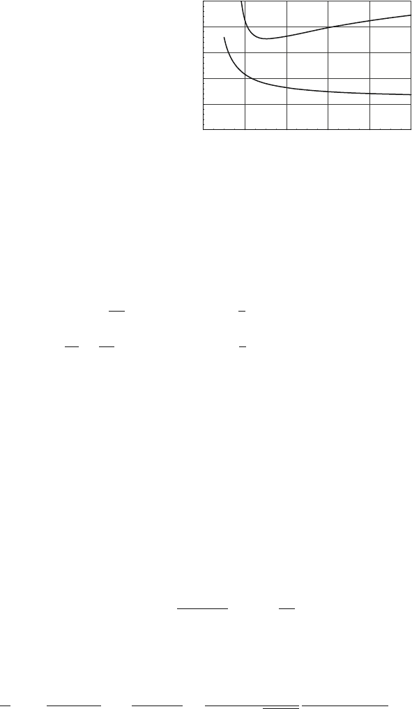
Fig. 6.40 The factor by
which the equivalent noise
charge ENC of a unipolar and
a bipolar shaper with the
same peaking time differs
from the minimum obtainable
ENC, represented as a
continuous function of n,the
number of stages. Upper
curve: bipolar shaper; lower
curve: unipolar shaper
2 4 6 8 10
n
1.1
1.2
1.3
1.4
1.5
(4KpKs)^1/4
The factor (4K
p
K
s
)
1/4
tells us the amount by which the ENC for a given amplifier
transfer function differs from the theoretical minimum. Figure 6.40 shows this value
for the unipolar and the bipolar shaper.
It is interesting to investigate how the parameters K
p
and K
s
are related to the
actual shape of the electronics delta response. With the help of Parseval’s theorem
we can perform the calculation of K
s
and K
p
in the time domain
K
p
t
p
=
1
2
π
∞
0
|H(i
ω
)|
2
d
ω
=
1
2
∞
0
h(t)
2
dt, (6.120)
K
s
t
p
=
1
2
π
∞
0
|
ω
H(i
ω
)|
2
d
ω
=
1
2
∞
0
h
(t)
2
dt. (6.121)
The parallel noise is given by the time integral over h(t), which means that it in-
creases as the length of the electronic delta response, and so the peaking time
increases. The series noise is given by the integral over the derivative of h(t), and
because a shorter delta response has steeper rising and falling edges, the series noise
decreases for increasing peaking time.
Up to now we have examined how to minimize the variance
σ
2
v
of the amplifier
output noise, which is equivalent to maximizing the signal-to-noise ratio when the
chamber signal is a delta pulse I(t)=Q
δ
(t).
However, our wire signal is different from a delta signal and shows the 1/(t +t
0
)
time dependence. As discussed in Sect. 6.2.1 the peak of the amplifier output signal
is approximately given by the charge integrated during the duration T
I
≈t
p
/2ofthe
‘flat top’ of the delta response, i.e.,
v
p
(t
p
) ≈ gQ(t
p
) ≈
gq
2ln(b/a)
ln
1+
t
p
2t
0
. (6.122)
If we want to optimize the signal-to-noise ratio we must find the best peaking time
t
p
by maximizing the expression
S
N
2
=
Q
p
(t
p
)
2
ENC
2
(t
p
)
=
q
2ln(b/a)
2
2
ENC
min
4K
s
K
p
ln
2
(1+t
p
/2t
0
)
t
p
/t
opt
+t
opt
/t
p
,
6.3 Noise and Optimum Filters 229
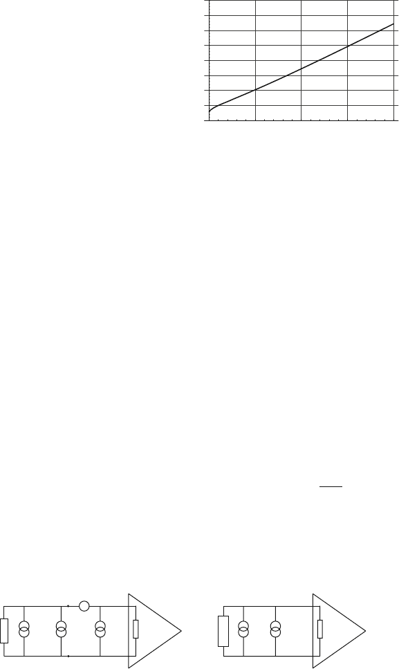
Fig. 6.41 Optimum peaking
time t
Wire
opt
for a wire chamber
signal as a function of the
time constant t
0
, normalized
to t
δ
opt
which is the optimum
peaking time for a delta input
signal
0.5 1 1.5 2
2.5
5
7.5
10
12.5
15
17.5
20
t
opt
/ t
opt
wire
δ
t
0
/ t
opt
δ
where t
opt
gives the optimum signal-to-noise ratio for a delta input signal. The max-
imum of the expression can only be found numerically, and Fig. 6.41 shows the
optimum peaking time as a function of the signal tail t
0
.
For t
0
values that are much shorter than t
δ
opt
the wire chamber signal closely
resembles a delta pulse and the optimum peaking time for the wire readout is equal
t
δ
opt
. In the case where t
0
is similar to or longer than t
δ
opt
, the optimum peaking time
t
Wire
opt
is longer because integrating more of the induced charge is still improving the
signal-to-noise ratio.
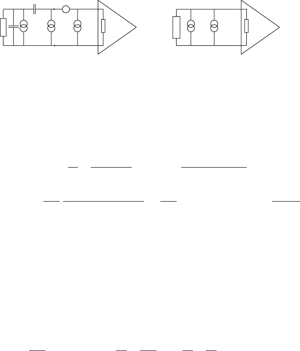
Terminated Transmission Line
If the signal propagation time along an electrode is of the same order as the signal
pulse width as illustrated in Fig. 6.42, the electrode must be terminated in order to
avoid multiple signal reflections. A transmission line with characteristic impedance
Z
0
can be terminated with a resistor R
T
= Z
0
. In this case, Z(s) consists of a sim-
ple resistor R
T
, which represents all the electrical characteristics of a terminated
transmission line. The chamber model parameters are given by
Z(s)=R
T
I(s)=I
ind
(s) w
i
( f )=
4kT
R
T
. (6.123)
While the load resistor R
L
for the wire channel is usually dimensioned such that
it is a negligible source of noise compared to the amplifier noise, the termination
e
n
2
(f)
i
n
2
(f)
w
i
(f)
Z
in
(s)
Z(s)
=
Z
in
(s)
gH(s)
gH(s)
I
ind
(s)
w(f)I(s)
R
Fig. 6.42 Transmission line channel connected to to an amplifier and the universal model of the
readout channel
230 6 Electronics for Drift Chambers
resistor R
T
of a transmission line is uniquely defined by the chamber geom-
etry and has typical values of 50–500
Ω
. Therefore it is usually the termina-
tion resistor noise that dominates over the amplifier noise for a transmission line
readout.
The equivalent input noise is
w( f )=
4kT
R
T
+ i
2
n
+
e
2
n
R
2
T
=
4kT
R
T
1+
R
T
R
p
+
R
s
R
T
+
B
ω
R
2
T
. (6.124)
For this discussion we neglect the 1/ f noise by setting B = 0, but because the order
of magnitude of the input impedance is similar to the chamber impedance we cannot
neglect Z
in
as was done for the cathode channel. We therefore have
I
in
(s)=
R
T
R
T
+ R
in
I(s)=
γ
I(s) w
in
( f )=
γ
2
w( f ). (6.125)
The output noise for the unipolar and the bipolar shaper is therefore
σ
2
v
=
γ
2
g
2
1
2
π
∞
0
w
in
( f )=g
2
γ
2
4kT
R
T
1+
R
T
R
p
+
R
s
R
T
K
p
t
p
. (6.126)
First we see that the noise r.m.s. is monotonically increasing with the peaking time
t
p
, so the smallest noise r.m.s. is achieved for the shortest peaking time. To find the
ENC we send, as before, a delta signal Q
δ
(t) into the amplifier, which gives the
output pulse height v
p
= g
γ
Q, so the equivalent noise charge is
ENC
2
=
4kT
R
T
1+
R
T
R
p
+
R
s
R
T
K
p
t
p
= c
1
t
p
. (6.127)
For the cathode channel discussed in the previous section, the noise is entirely de-
fined by the amplifier noise i
2
n
and e
2
n
and therefore depends only on the amplifier
design. For the terminated transmission line channel, the noise of the termination
resistor represents an irreducible noise floor and the amplifier noise is negligible
when R
p
R
T
and R
s
R
T
.
As before, we are interested in optimizing the signal-to-noise ratio for the wire
chamber signal:
S
N
2
=
Q
p
(t
p
)
2
ENC
2
(t
p
)
=
Q
2ln
b
a
2
ln
2
(1+t
p
/2t
0
)
c
1
t
p
→ max.
The numerical evaluation shows that the expression has a maximum at t
p
≈ 8t
0
.
If the input signal were a delta current pulse the signal-to-noise ratio would con-
tinuously improve by reducing the amplifier peaking time. Since the wire chamber
signal has a tail and the induced charge only increases with the logarithm of time,
there is an optimum amplifier peaking time, that maximizes the signal-to-noise
ratio.
6.3 Noise and Optimum Filters 231
e
n
2
(f)
i
n
2
(f)
w
i
(f)
Z
in
(s)
Z(s)
=
Z
in
(s)
gH(s) gH(s)
I
ind
(s)
w(f)I(s)
R
L
C
C
D
Fig. 6.43 Wire connected to to an amplifier and the universal model of the readout channel
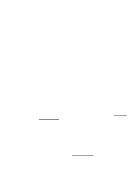
Wire Channel
The case shown in Fig. 6.43 contains more elements than there were for the cathode
and the transmission line channels. For the wire channel we have the following
electrical parameters:
Z(s)=
1
sC
+
R
L
1+ sR
L
C
D
I(s)=
sR
L
C
1+ sR
L
(C +C
D
)
I
ind
(s)
w
i
( f )=
4kT
R
L
(
ω
R
L
C)
2
1+(
ω
R
L
(C +C
D
))
2
≈
4kT
R
L
for C C
D
f
1
2
π
R
L
C
.
The loading resistor R
L
is a source of thermal noise which is ‘filtered’ by the detector
capacitance C
D
and the decoupling capacitor C. The expression for w
i
( f ) represents
the white noise of the resistor filtered by a high-pass filter with time constant
τ
=
R
L
C. With the typical numbers of R
L
= 1M
Ω
and C = 1nF we have
τ
= 1ms.
Therefore, only frequencies of f < 160 Hz are attenuated, which is negligible for the
typical amplifier bandwidth of a few MHz, and we can neglect the effect of C and
C
D
. We assume again that the amplifier input resistance is negligible with respect
to the chamber impedance and we also neglect the 1/ f noise term. The equivalent
input noise is then
w( f )=
4kT
R
L
+i
2
n
+
ω
2
C
2
D
e
2
n
+
e
2
n
R
2
L
=
4kT
R
L
1+
R
s
R
L
+
R
L
R
p
+4kTR
s
ω
2
C
2
D
. (6.128)
This expression has the same form as the one for the cathode channel and the results
from there apply to this case as well.
We have seen that the unipolar shaper gives a better signal-to-noise ratio than the
bipolar shaper, but the question arises as to whether one can improve the situation
still more by yet another kind of electronics transfer function. This problem can be
solved in a remarkably general and elegant way, and it is possible find the maximum
obtainable signal-to-noise ratio from the amplifier input signal and the spectral noise
density at the amplifier input.
6.3.4 A Universal Limit on the Signal-to-Noise Ratio
In the last sections we found that we get different ENC values for different ampli-
fier transfer functions, and that for a specific shape of a delta response there is an
232 6 Electronics for Drift Chambers
optimum peaking time. We found that the unipolar shaper results in a smaller ENC
than the bipolar shaper, and the question arises as to whether we can decrease the
noise level by yet another transfer function. Or going even further we can ask, what
is the maximum obtainable signal-to-noise ratio?
The reason the signal-to-noise ratio can be improved by specific filters is the fact
the signal and the noise have different frequency spectra. So it is possible to improve
the signal-to-noise ratio by specific filters. The mathematical problem that we have
to solve can be formulated as shown in what follows.
A signal F(i
ω
) with a superimposed noise having a power spectrum w(
ω
) is
processed by an amplifier with transfer function H(i
ω
). Which transfer function
H(i
ω
) maximizes the signal-to-noise ratio?
Using Eq. 6.3 and 6.84 we can write the amplifier output signal g(t) and the
variance of the noise at the amplifier output as
g(t)=
1
2
π
∞
−∞
F(i
ω
)H(i
ω
)e
i
ω
t
d
ωσ
2
=
1
2
π
∞
0
w(
ω
)|H(i
ω
)|
2
d
ω
. (6.129)
The output signal g(t) has a maximum at some time t
m
when the signal-to-noise
ratio S/N at the amplifier output is
S
N
2
=
g(t
m
)
σ
2
=
1
π
∞
−∞
F(i
ω
)H(i
ω
)e
i
ω
t
m
d
ω
2
∞
−∞
w(
ω
)|H(i
ω
)|
2
d
ω
. (6.130)
This expression has an upper limit given by the Schwarz inequality, which gives the
following relation for two complex-valued functions
ψ
(x) and
φ
(x):
b
a
ψ
∗
(x)
φ
(x)dx
2
≤
b
a
|
ψ
(x)|
2
dx
b
a
|
φ
(x)|
2
dx, (6.131)
where the equal sign applies if
ψ
(x)=c
1
φ
(x) (c
1
=const). If we insert
ψ
(
ω
)=
F
∗
(i
ω
)
w(
ω
)
e
−i
ω
t
m
φ
(
ω
)=
w(
ω
)H(i
ω
) (6.132)
and extend the integration limits to infinity, the inequality reads as
∞
−∞
F(i
ω
)H(i
ω
)e
i
ω
t
m
d
ω
2
≤
∞
−∞
|F(i
ω
)|
2
w(
ω
)
d
ω
∞
−∞
w(
ω
)|H(i
ω
)|
2
d
ω
, (6.133)
and therefore
S
N
2
≤
1
π
∞
−∞
|F(i
ω
)|
2
w(
ω
)
d
ω
=
2
π
∞
0
|F(i
ω
)|
2
w(
ω
)
d
ω
. (6.134)
This result is remarkable in two respects. On the one hand, the solution to the prob-
lem is surprisingly simple, while, on the other hand, the result has far-reaching
consequences: Whichever transfer function H(i
ω
) we choose, the (S/N) will always
6.3 Noise and Optimum Filters 233
be lower than the value indicated above, which can be calculated in a straightforward
fashion from the signal and the noise spectrum at the amplifier input.
Now we would like to know the optimum transfer function H(i
ω
) and the output
signal G(i
ω
). From the above relations we find that the equal sign applies if
F
∗
(i
ω
)
w(
ω
)
e
−i
ω
t
m
= c
1
w(
ω
)H(i
ω
) → H(i
ω
)=
1
c
1
F
∗
(i
ω
)
w(
ω
)
e
−i
ω
t
m
. (6.135)
We can omit the factor exp(−i
ω
t
m
) because it corresponds simply to a time delay
t
m
according to Eq. (6.4e). This transfer function is unique up to a constant, and
it provides the maximum signal-to-noise ratio. The amplifier output signal is then
proportional to
G(i
ω
)=F(i
ω
)H(i
ω
)=
|F(i
ω
)|
2
w(
ω
)
g(t)=F
−1
[G(i
ω
)]. (6.136)
We note that this signal g(t) is symmetric around t = 0 because G(i
ω
) is real.
As an example we consider a wire chamber cathode pad channel, where we found
a noise power spectrum of w(
ω
)=4kT/R
p
+ 4kTR
s
C
2
D
ω
2
= a
2
+ b
2
ω
2
. Assum-
ing that the detector signal is a delta current pulse, we find the following optimum
signal-to-noise ratio
f (t)=Q
δ
(t) F(i
ω
)=Q
S
N
2
≤
2
π
∞
0
Q
2
a
2
+ b
2
ω
2
d
ω
=
Q
2
ab
(6.137)
The optimum transfer function is
H(i
ω
)=
1
c
1
Q
a
2
+ b
2
ω
2
h(t)=F
−1
[H(i
ω
)] = c
2
e
−|t|/
τ
c
τ
c
=
b
a
. (6.138)
The time constant
τ
c
is called the noise corner time constant. The delta response of
the optimum filter h(t) has a peak at t = 0 and is symmetric around t = 0 from where
it decays exponentially. This delta response is called the ‘infinite cusp’ function. As
we saw earlier, a unipolar shaper with n = 6 results in a signal-to-noise ratio that is
just 15% worse than the optimum one that would be achieved by using the infinite
cusp delta response.
The current signals in a wire chamber are not delta currents but have the hy-
perbolic 1/(t + t
0
) form. If we use several pole-zero filters to remove the signal
tail such that only a single exponential is left, the chamber signal is given by
f (t)=A
1
exp(−t/
τ
1
) and the maximum achievable signal-to-noise ratio is smaller
than the one described above. By writing the signal amplitude in terms of the signal
charge Q =
f (t)dt = A
1
τ
1
,wehave
f (t)=
Q
τ
1
e
−t/
τ
1
F(i
ω
)=
Q
τ
1
1
i
ω
+ 1/
τ
1
S
N
2
≤
Q
2
ab(1+
τ
1
/
τ
c
)
.
(6.139)
234 6 Electronics for Drift Chambers
In a previous section we found that it is very useful to approximate the cham-
ber signal by a sum of exponentials, which can be done for every possible signal
shape to any desired accuracy. By evaluating the above expressions for an in-
put signal of the form f (t)=
∑
N
n=1
A
n
exp(−t/
τ
n
) we can find the maximum
achievable signal-to-noise ratio for an arbitrary signal shape. We again write the
amplitudes in terms of the charge ‘contained’ in each exponential Q
n
= A
n
τ
n
.The
result is
S
N
2
≤
1
ab
N
∑
n=1
N
∑
m=1
Q
m
1+
τ
m
/
τ
c
Q
n
1+
τ
n
/
τ
c
1+
2
τ
m
τ
n
τ
c
(
τ
n
+
τ
m
)
. (6.140)
The expression can be used to investigate by what factor the noise for a realistic
amplifier transfer function deviates from the theoretical minimum.
6.4 Electronics for Charge Measurement
In the previous sections we discussed the processing of a wire chamber signal for
several typical electrode configurations, including the effects of electronic noise. Up
to now the signal induced on the electrode was assumed to have the form 1/(t + t
0
),
which is characteristic for any electrode configuration as long as the avalanche elec-
trons are moving in the coaxial region of the wire.
However, the signal shape applies only for a single electron that arrives at the
wire and creates a single avalanche. It would also apply for a localized cloud of
electrons arriving within a time shorter than t
0
. But the time spread of the incoming
electrons is generally much larger than t
0
, so the total signal is a superposition of
single-electron signals i
0
(t)=I
0
/(1+t/t
0
),
i
ind
(t)=
N
∑
n=1
G
n
i
0
(t −t
n
), (6.141)
with arrival times t
n
and avalanche sizes G
n
. The output of the front-end electronics
is then also a linear superposition of the responses to the single electron pulses. The
question arises as to how we choose the transfer function H(i
ω
) in order to arrive
at the best signal-to-noise ratio for this situation. Clearly, the electron arrival times
vary from event to event and the electronics can only be adjusted for an average
situation.
We first investigate the case of a TPC, where the arrival of the electrons at the
sense wires assumes a Gaussian form owing to the diffusion along the drift path. If
we define an arrival time distribution n(t) such that n(t)dt is the average number of
electrons that arrive between t and t + dt,wehave
n(t)dt =
N
√
2
πσ
t
e
−(t−T)
2
/2
σ
2
t
dt, (6.142)

6.5 Electronics for Time Measurement 235
where
σ
t
characterizes the electron diffusion along the drift path. Each arriving elec-
tron will induce a signal of the form Gi
0
(t), where G is the gas gain, and the discrete
sum of time-delayed signals of Eq. (6.141) becomes a convolution of n(t) with i
0
(t):
i(t)=G
∞
−∞
i
0
(t −t
)n(t
)dt
. (6.143)
We realize that from a formal point of view, the arrival time distribution n(t) en-
ters like a linear signal processing device in an electronics chain. Using the Fourier
transform of n(t) we see that this becomes even more evident because we have
I(i
ω
)=GI
0
(i
ω
)N(i
ω
). (6.144)
We can therefore apply all the results from the previous sections for optimizing the
electronic transfer function in order to achieve the best signal-to-noise ratio.
The optimum achievable signal-to-noise ratio for the average signal is given by
S
N
2
=
G
2
π
∞
−∞
|I
0
(i
ω
)N(i
ω
)|
2
w(
ω
)
d
ω
. (6.145)
If we assume that for reasons of high rate we remove the signal tail with a series
of pole-zero filters such that the single electron signal assumes an exponential form
with a time constant
τ
which is negligible with respect to the arrival time distribu-
tion, we can assume I
0
(t)=Q
δ
(t). If we assume in addition that the superimposed
noise is white, the optimum transfer function according to Eq. (6.135) is
H(i
ω
)=
N
∗
(i
ω
)
w
0
, (6.146)
a Gaussian with the same width as the arrival time distribution.
With a wire chamber geometry shown in Chap. 7 the arrival time distribution will
be different from track to track, depending on the incident angle, the path length
variation, and diffusion. The distribution n(t) is given by the function f
z
(t, y) in
Eq. (7.7) and results in a width given by Eqs. (7.8) and (7.9). The optimizing process
can then be conducted as before. In general the optimum amplifier peaking time is
such that the width of the delta response is approximately equal to the electron
arrival time distribution.
The actual measurement of the charge can be done in different ways. One either
records the peak of the signal by a so-called ‘peak sensing ADC’, or one samples
the signal at regular intervals and reconstructs the signal peak by fitting the known
response to the sample points.
6.5 Electronics for Time Measurement
In this section we investigate which front-end electronics should be used in order
to extract the best time information from the chamber signal. In drift chambers, the
time information is used to determine the track position by measuring the arrival
236 6 Electronics for Drift Chambers
time of the ionization electrons at the sense wires. In so-called trigger chambers, the
time information is used to determine the time when a charged particle is passing
the detector. For the choice of the transfer function H(i
ω
) which optimizes the time
measurement accuracy we have to consider several effects: the electronic noise,
pulse-height fluctuations, and the arrival time distribution of the electrons.
The fluctuations of the electron arrival times are discussed in detail in Sect. 7.4.
For long electron drift distances the diffusion effect dominates and the average elec-
tron arrival time gives the best time measurement. For short drift distances, the
primary ionization fluctuations together with effects such as track inclination and
path length variations dominate and the first arriving electrons show the smallest
arrival time fluctuations. Mathematically, the optimum time measurement would be
achieved by recording the arrival time of each individual electron and performing
statistical analyses of the electron arrival time spectrum for each event. Clearly this
is not practical. With realistic front-end electronics we can approximately realize
some effective weighting of the arrival times and we can choose whether the time
information should be given by the first electrons or some effective average of sev-
eral arriving electrons.
There are several ways of extracting the time information from the signal. We can
record the signal shape by sampling the signal at regular intervals and find the time,
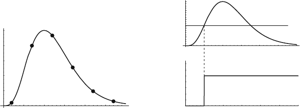
e.g., by fitting the known average pulse shape to the signal as shown in Fig. 6.44a.
This requires of course the recording of multiple data points per signal, and it is only
useful in detectors where the signal shape does not vary significantly from event to
event. In the following we discuss how to directly extract a single time value from
the signal by applying a discriminator, as shown in Fig. 6.44b. A discriminator is
a device that creates a square ‘logic’ output pulse when the input signal crosses a
certain applied threshold. The edge of the logic pulse can then be measured by a
suitable device, typically called a time to digital converter (TDC). For the discus-
sion of the individual contributions to the time resolution we need the following
expressions: the current signal i
0
(t) induced by a single ion moving from the wire
5 10 15 20 25 30
20
40
60
80
100
5 10 15 20 25 30
0.2
0.6
1.4
1
Time (ns)
0
0
Threshold (mV)
5 10 15 20 25 30
20
40
60
80
100
Signal (mV)
Time (ns)
(a) (b)
Fig. 6.44 (a) Sampling of the signal in regular time intervals for extraction of time time informa-
tion. (b) Application of a discriminator to the signal where the time information is determined by
the threshold crossing time