Blum W., Riegler W., Rolandi L. Particle Detection with Drift Chambers
Подождите немного. Документ загружается.

Chapter 5
Creation of the Signal
The moving charges in a chamber give rise to electrical signals on the electrodes
that can be read out by amplifiers. The electrons created in the avalanche close to the
wire move to the wire surface within a time typically much less than a nanosecond,
resulting in a short signal pulse. The ions created in the avalanche move away from
the wire with a velocity about a factor 1000 smaller, which results in a signal with
a long tail of typically several hundred microseconds duration. The movement of
these charges induces a signal not only on the wire but also on the other electrodes
in the chamber, so for the purpose of coordinate measurements the cathode can
be subdivided into several parts. In this chapter we derive very general theorems
that allow the calculation of signals in wire chambers and present some practical
examples.
5.1 The Principle of Signal Induction by Moving Charges
In order to understand how moving charges give rise to signals on electrodes we
first consider the simple example shown in Fig. 5.1a [JAC 75]. A point charge
q in the presence of a grounded metal plate induces a charge on the metal sur-
face. This surface charge can be calculated by solving the Poisson equation for
the potential
φ
with a point charge q at z = z
0
and the boundary condition that
φ
= 0atz = 0. Gauss’ law tells us that the resulting electric field E = −∇
φ
on the metal surface is related to the surface charge density
σ
by
σ
(x,y)=
ε
0
E(x, y,z = 0). The solution for this particular geometry can be found by assum-
ing a mirror charge −q at z = −z
0
. The electric field on the metal surface is thus
given by
E
z
(x,y)=−
qz
0
2
πε
0
(x
2
+ y
2
+ z
2
0
)
3
2
E
x
= E
y
= 0, (5.1)
and the surface charge density is
σ
(x,y)=
ε
0
E
z
(x,y). The total charge induced on
the metal plate is therefore
W. Blum et al., Particle Detection with Drift Chambers, 157
doi: 10.1007/978-3-540-76684-1
4,
c
Springer-Verlag Berlin Heidelberg 2008
158 5 Creation of the Signal
0
q
σ (x,y)
0
q
0 000
Q
1
(t) Q
2
(t) Q
3
(t)
v
w
I
1
(t)
I
2
(t)
I
3
(t)
a)
b)
z = z
o
z = 0
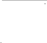
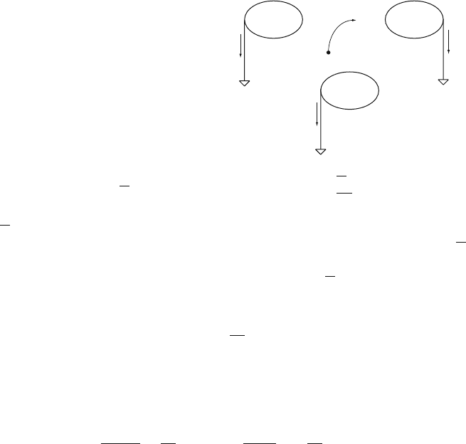
Fig. 5.1 (a) A point charge q induces a charge density
σ
(x,y) on the surface of a grounded metal
plate. (b) Segmenting the metal plate results in induced charges Q
n
on the strips. In case q is
moving, the induced charges on the strips are changing and currents are flowing between the
strips and ground
Q =
∞
−∞
∞
−∞
σ
(x,y)dxdy = −q, (5.2)
and it is independent of the distance of the charge q from the metal plate. Let us now
imagine the metal plate to be segmented into strips of width w, each of the strips
being grounded (Fig. 5.1b). In order to find the charge induced, e.g., on the central
strip, we have to integrate the surface charge density from Eq. (5.1) over the area of
the strip:
Q
1
(z
0
)=
∞
−∞
w/2
−w/2
σ
(x,y)dxdy = −
2q
π
arctan
w
2z
0
. (5.3)
This induced charge now depends on the distance z
0
of the point charge q from
the metal surface. If the charge is moving towards the metal strip with a velocity v
according to z
0
(t)=z
0
−vt, we find a time-dependent-induced charge Q
1
[z
0
(t)] and
thus an induced current of
I
ind
1
(t)=−
d
dt
Q
1
[z
0
(t)] = −
∂
Q
1
[z
0
(t)]
∂
z
0
dz
0
(t)
dt
=
4qw
π
[4z
0
(t)
2
+ w
2
]
v. (5.4)
We see that the movement of a charge induces a current which flows between the
electrode and ground. This is the principle of signal induction by moving charges.
For more realistic geometries, this method of calculating the signals is the same but
can become quite complex. In the following we derive theorems that allow a simpler
and more intuitive way of calculating signals induced on grounded electrodes. After
that we investigate the signals for the scenario where the electrodes are not grounded
but are connected to amplifiers or interconnected by a general reactive network.
5.2 Capacitance Matrix, Reciprocity Theorem
The capacitance matrix and the reciprocity theorem are the bases for the discussion
of signals induced on metal electrodes. The expression ‘metal’ electrode refers to the
condition that the charges on the electrode can move and that the electrode surface
5.2 Capacitance Matrix, Reciprocity Theorem 159
is therefore an equipotential one. Setting a set of N metal electrodes to voltages
V
n
defines the potential
φ
(x) and the resulting electric field E(x)=−∇
φ
(x) in
the chamber volume. The potential is uniquely defined by the conditions that
φ
(x)
satisfies the Laplace equation and that
φ
(x)=V
n
on the electrode surfaces.
Figure 5.2a shows a set of three metal electrodes. The voltages V
n
and charges
Q
n
on the electrodes are related by the capacitance matrix of the electrode system
[JAC 75]:
Q
n
=
N
∑
m=1
c
nm
V
m
. (5.5)
The capacitance matrix is defined by the electrode geometry, and for the capacitance
matrix elements c
nm
, the following relations hold:
c
nm
= c
mn
, c
nm
≤ 0forn = m, c
nn
≥ 0,
N
∑
m=1
c
nm
≥ 0. (5.6)
These relations are a direct consequence of Green’s second theorem and the fact
that the potential has to satisfy the Laplace equation. A set of different voltages
V
n
is related to a set of different charges Q
n
by the same capacitance matrix Q
n
=
∑
c
nm
V
m
, so by inverting this relation and multiplying it by Eq. (5.5) we find
N
∑
n=1
Q
n
V
n
=
N
∑
n=1
Q
n
V
n
. (5.7)
This relation is called is called the reciprocity theorem and we use it frequently in
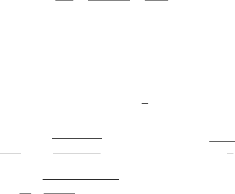
the following discussions. Another important relation concerns the sum of all the
charges of an electrode system. Figure 5.2b shows an electrode surrounding three
electrodes. We apply Gauss’ law to the volume between the electrodes, which tells
us that the sum of all charges within this volume is equal to
ε
0
times the integral of
E(x) over the surface surrounding it. Because
ε
0
E(x)dA over a metal electrode
is equal to the charge on this electrode, we find that the sum of all charges on the
V
1
Q
1
V
2
Q
2
V
3
Q
3
V
4
Q
4
q
2
q
1
b)
V
1
Q
1
V
2
Q
2
V
3
Q
3
a)
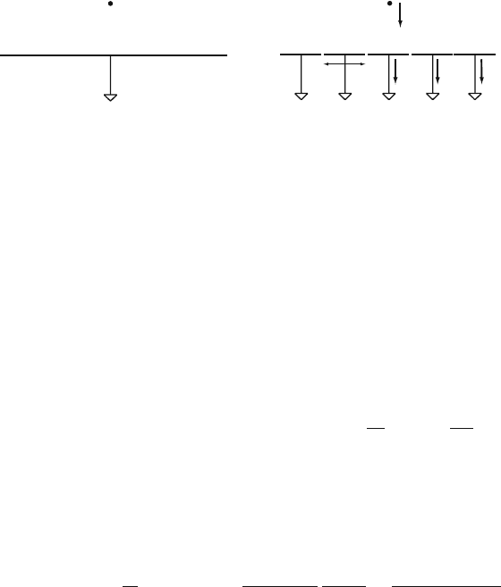
Fig. 5.2 (a) The voltages and charges in a system of electrodes are related by the capacitance
matrix c
nm
. (b) A set of metal electrodes where one electrode encloses the others. The sum of all
charges Q
n
on the electrodes is equal to the sum of all charges q
n
in the volume between the
electrodes
160 5 Creation of the Signal
metal electrodes is equal to the sum of all charges in the volume between the elec-
trodes! In the case where there are no charges in the volume between the electrodes,
the sum of the charges Q
n
on the electrodes must be zero for any set of voltages V
n
applied to them. Thus for the capacitance matrix we find the relation
∑
n
Q
n
= 0 →
∑
n
∑
m
c
nm
V
m
= 0 →
∑
n
c
nm
= 0, (5.8)
which means that for a set of electrodes that is enclosed by one of them, the sum of
all columns (rows) of the capacitance matrix is equal to zero.
To conclude this section we note that the capacitance matrix elements c
nm
are
different from the more familiar capacitances C
nm
that we know from electric circuit
diagrams. The C
nm
are related to the voltage difference between circuit nodes, and
we show later that the c
nm
and C
nm
are related by
C
nn
=
N
∑
m=1
c
nm
, C
nm
= −c
nm
if n = m. (5.9)
5.3 Signals Induced on Grounded Electrodes, Ramo’s Theorem
We consider a set of three grounded electrodes in the presence of a point charge
Q
0
= q at position x as shown in Fig. 5.3a. We assume the point charge Q
0
to be
sitting on an (infinitely small) metal electrode, so we have a system of four metal
electrodes. For this setup we haveV
1
=V
2
=V
3
= 0 and we want to know the charges
Q
1
,Q
2
,Q
3
induced by the presence of charge Q
0
= q. Equation (5.7) reads
q
V
0
+ Q
1
V
1
+ Q
2
V
2
+ Q
3
V
3
= Q
0
V
0
. (5.10)
Choosing another electrostatic state (Fig. 5.3b), where we remove the charge q from
the small electrode (
Q
0
= 0), we set electrode 1 to voltage V
w
(V
1
= V
w
) while
keeping the other electrodes grounded (
V
2
= V
3
= 0), the above relation becomes
Q
1
V
1
=
0
Q
2
Q
3
V
2
=
0
V
3
=
0
Q
0
=
q
V
0
x
0
0
0
Q
1
V
1
=
V
w
Q
2
Q
3
V
2
=
0
V
3
=
0
Q
0
=
0
V
0
=
ψ
1
(x)
0
0
(a)
(b)
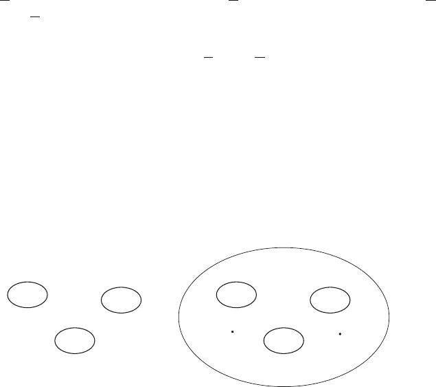
Fig. 5.3 (a) The point charge q induces charges Q
n
on the grounded electrodes. (b) Another set of
voltages and charges which defines the ‘weighting potential’ of the first electrode
5.4 Total Induced Charge and Sum of Induced Signals 161
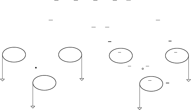
Fig. 5.4 In the case where
the charge q is moving there
are currents flowing between
the electrodes and ground.
The definition of I = −dQ/dt
indicates that the positive
current points away from the
electrode
Q
1
(t)
q
x(t)
0
0
0
I
1
(t) I
2
(t)
I
3
(t)
Q
2
(t)
Q
3
(t)
qV
0
+ Q
1
V
w
= 0 → Q
1
= −q
V
0
V
w
. (5.11)
V
0
is the potential of the uncharged small electrode for the second electrostatic state,
and since an infinitely small uncharged electrode is equal to having no electrode,
V
0
is the potential at point x when the point charge q is removed, electrode 1 is put to
potential V
w
, and electrodes 2 and 3 are grounded. We call V
0
=
ψ
1
(x) the weighting
potential of electrode 1, and the induced charge Q
1
is given by
Q
1
= −
q
V
w
ψ
1
(x). (5.12)
In the case where the point charge q is moving along a trajectory x(t),asshown
in Fig. 5.4, we find a time-dependent-induced charge on electrode n and therefore a
current of
I
ind
n
(t)=−
dQ
n
(t)
dt
=
q
V
w
∇
ψ
n
[x(t)]
dx(t)
dt
= −
q
V
w
E
n
[x(t)] v(t). (5.13)
We call E
n
(x)=−∇
ψ
n
(x) the weighting field of electrode n, which is Ramo’s
theorem [RAM 39]:
The current induced on a grounded electrode by a point charge q moving along
a trajectory x(t) is I
ind
n
(t)=−q/V
w
E
n
[x(t)] v(t), where E
n
(x) is the electric field
in the case where the charge q is removed, electrode n is set to voltage V
w
, and all
other electrodes are grounded.
It must be noted that the sign of the induced current is given not only by the sign
of the charge but also by the orientation of the particle velocity vector with respect
to the direction of the weighting field. The trajectory x(t) is determined by the ‘real’
electric and magnetic fields in the detector together with the drift properties of the
electrons and ions in the detector gas.
5.4 Total Induced Charge and Sum of Induced Signals
If the charge q is moving along a trajectory x(t) from position x
0
= x(t
0
) to position
x
1
= x(t
1
), the total amount of charge Q
ind
n
that flows between electrode n and
ground is given by
162 5 Creation of the Signal
Q
ind
n
=
t
1
t
0
I
ind
n
(t)dt = −
q
V
w
t
1
t
0
E
n
[x(t)] ˙x(t)dt =
q
V
w
[
ψ
n
(x
1
) −
ψ
n
(x
0
)]. (5.14)
We find that this induced charge depends only on the end points of the trajectory and
is independent of the specific path. If a pair of charges q, −q is produced at point x
0
at t = t
0
and q arrives at position x
1
while −q arrives at position x
2
after a time t
1
,
the charge induced on electrode n is given by
Q
ind
n
=
t
1
t
0
I
ind
n
(t)dt =
q
V
w
[
ψ
n
(x
1
) −
ψ
n
(x
2
)]. (5.15)
If the charge q moves to the surface of electrode n while the charge −q moves to
the surface of some other electrode, the total induced charge on electrode n is equal
to q, since
ψ
n
= V
w
on electrode n and
ψ
n
= 0 on the other electrodes. When both
charges move to other electrodes, the total induced charge on electrode n is zero.
We can therefore conclude:
After all the charges have arrived at the different electrodes, the total charge
induced on electrode n is equal to the charge that has arrived at electrode n.
From this we also conclude that the current signals on electrodes that do not
receive any charge are strictly bipolar.
If we want to know the sum of the signals induced on several electrodes we can
either calculate the weighting fields and induced currents for the individual elec-
trodes and add the currents or we can calculate the weighting field for the entire set
of electrodes by setting all of them to voltage V
w
and grounding the remaining ones.
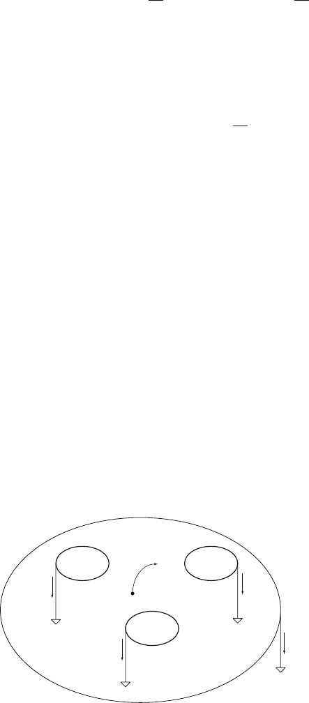
Let us assume the set of electrodes shown in Fig. 5.5, where one electrode encloses
the others. The weighting potential
ψ
tot
for the sum of all induced currents is defined
by setting all electrodes to potential V
w
. This, however, results in
ψ
tot
(x)=V
w
in the
entire volume and consequently a weighting field of E
tot
(x)=0. We can therefore
conclude:
The sum of all induced currents on grounded electrodes is zero at any time, pro-
vided there is one electrode enclosing all the others.
1
q
x
0
(t)
0
0
0
I
1
(t) I
2
(t)
I
3
(t)
2
3
0
4
I
4
(t)
Fig. 5.5 A set of grounded electrodes enclosed by one electrode. The sum of all induced currents
is zero at any given time
5.5 Induced Signals in a Drift Tube 163
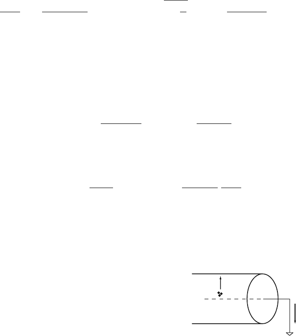
5.5 Induced Signals in a Drift Tube
As an example we calculate the induced signal in a drift tube with (cathode) radius b
and wire radius a (Fig. 5.6). The tube is set to potential −U and the wire is grounded.
This results in an electric field of E(r)=U/(r ln(b/a)), as calculated in Sect. 3.1.1.
We assume a single primary electron-ion pair in the gas volume. The electron moves
to the wire and the ion moves to the tube wall. Close to the wire the electron starts an
avalanche creating N
tot
electrons and ions. The N
tot
electrons of charge −e
0
move to
the wire surface within a time much less than a nanosecond. The N
tot
ions of charge
+e
0
move away from the wire, but much more slowly, arriving at the tube wall after
a time typically several hundreds of microseconds. As a first step we simply assume
that the N
tot
electrons are created at the wire surface and so do not move, while the
N
tot
ions move from the wire surface to the tube wall. The velocity of the ions is
given by the mobility
μ
as v =
μ
E, so with the condition that r(t = 0)=a we find
the ion trajectory to be
dr(t)
dt
=
μ
U
r(t)ln(b/a)
→ r(t)=a
1+
t
t
0
t
0
=
a
2
ln(b/a)
2
μ
U
(5.16)
The characteristic time t
0
is typically one or a few nanoseconds. It takes very much
longer for the ions to arrive at the tube wall r = b; this maximum travel time is
t
max
= t
0
[(b/a)
2
−1], typically four to six orders of magnitude larger than t
0
,inthe
hundred microsecond range.
The weighting potential
ψ
1
and weighting field E
1
of the wire are defined by
setting the wire to potential V
w
and grounding the tube, which results in
ψ
1
(r)=−
V
w
ln(r/b)
ln(b/a)
E
1
(r)=
V
w
rln(b/a)
(5.17)
According to Eq. (5.13), the current induced on the wire by the movement of the
N
tot
ions is given by
I
ind
1
(t)=−
N
tot
e
0
V
w
E
1
[r(t)] ˙r(t)=−
N
tot
e
0
2ln(b/a)
1
t + t
0
. (5.18)
The wire signal is negative and has a hyperbolic form with a characteristic time
constant t
0
, which in practical cases will be a few nanoseconds. The induced charge
at time t is given by
Fig. 5.6 Ions moving from
thewiresurfacetothetube
wall induce a current signal
on the grounded wire
0
–U
I(t)
164 5 Creation of the Signal
Q
ind
1
(t)=
t
0
I
ind
1
(t
)dt
= −
N
tot
e
0
2ln(b/a)
ln
1+
t
t
0
. (5.19)
Once the ions have arrived at the tube wall the induced charge on the wire is
Q
ind
1
(t
max
)=−N
tot
e
0
, which agrees with the statement about the total induced
charge from the previous section. The current induced on the tube (‘the cathode’) is
I
ind
2
(t)=−I
ind
1
(t) since the tube completely encloses the wire and thus the sum of
the two signals must be zero at any time.
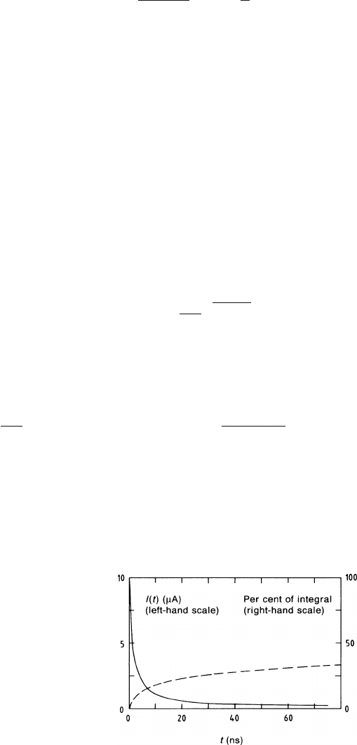
As an illustration, in Fig. 5.7 we plot the time development of a current pulse
described by Eqs. (5.18) and (5.19) using typical parameters for a,b, and t
0
.One
observes the extremely sharp onset and the extremely long tail characteristic of such
pulses.
In a second step we refine the picture by involving the radial extent of the
avalanche, the electron movement, and the field dependence of the ion mobility.
We use the model from Sect. 4.4.1, where the Townsend coefficient was taken to be
proportional to the electric field (
α
=(ln2/
Δ
V)E) and the first multiplication starts
at a minimum field E
min
. With E
min
= U/(r
min
ln(b/a)), the number of electrons
present at distance r is given by
N(r)=exp
r
min
r
α
(r)dr
=
r
min
r
U ln2
Δ
V ln(b/a)
(5.20)
The total number of avalanche electrons (the gain) is N
tot
= N(a). The number
of electrons created between r and r + dr is n(r)dr =(dN/dr)dr, so the centre of
gravity r
cog
of the electron avalanche is given by
r
cog
=
1
N
tot
r
min
a
rn(r) dr = a(1 +
ε
)
ε
=
Δ
V ln(b/a)
U ln2
(5.21)
Typical operating voltages U of ≈ 2kV,
Δ
V values of ≈ 20V, and ln(b/a) values
of ≈ 10 result in a value for
ε
of the order of 0.1. With traditional wire radii of
a = 10−30
μ
m we find that the centre of gravity of the electron avalanche is only a
few micrometers above the wire surface.
With such a small distance to travel to their destination, the wire surface, the
electrons can only make a small contribution to the total signal charge. The latter
Fig. 5.7 Current signal
according to (5.18) ( full
line, left-hand scale) for
t
0
= 1.25 ns, b/a = 500, and
q = 10
6
elementary charges.
Time integral (5.19) of this
pulse as a percentage of the
total (broken line, right-hand
scale)
5.6 Signals Induced on Electrodes Connected with Impedance Elements 165
one is given by Q
ind
tot
= −e
0
N
tot
once all the electrons and ions have arrived on
their respective electrodes (see the previous section). The signal from the electrons
may be calculated using Eq. (5.14), which tells us that a single electron moving
from distance r to the wire surface induces a charge of −(e
0
/ )(
ψ
1
(a) −
ψ
1
(r)) =
−e
0
ln(r/a)/ ln(b/a). Thus, assuming that all the electrons are moving from r
cog
to
the wire surface, the fraction of charge induced by the avalanche electrons is given
by
Q
ind
e
Q
ind
tot
=
ln(r
cog
/a)
ln(b/a)
≈
Δ
V
U ln2
. (5.22)
For typical values of U and
Δ
V discussed above, the fraction of charge induced
by the movement of the electrons amounts to 1 or 2% of the total induced charge.
Since the electrons arrive at the wire within a time much shorter than 1 ns, for all
practical purposes we can assume the electron component of the signal to be a delta
current I
ind
e
(t)=Q
ind
e
δ
(t). The ions move from their point of creation to the tube
wall, and we assume here that they all start from r
cog
. In the high electric fields of
10
3
–10
4
V/(cm Torr) in the vicinity of the wire, the ion velocity is not proportional
to E but rather is related to the field by v =
κ
√
E (Sect. 2.2.2). Thus, for the early
part of the ion trajectory we have
dr(t)
dt
=
κ
#
U
r(t)ln(b/a)
→ r(t)=a(1+
ε
)
1+
t
t
1
t
1
=
2
3
κ
ln(b/a)
U
a
3
(1+
ε
)
3
. (5.23)
In practice, t
1
is a small factor (say two or three times) larger than t
0
. It is remarkable
that the functional dependence on t is the same as the one of the simplified case of
Eq. (5.16). The refinements have only changed the numerical values of t
0
and a,so
the signal again assumes a hyperbolic form with a characteristic time constant t
1
.
The sharp onset and the long tail remain as shown in Fig. 5.7.
Since the electric field in the vicinity of the wire of any wire chamber has the
form 1/r, the universal shape of the induced current signal I
ind
1
(t) Eq. (5.18) is valid
for wire signals of all wire chamber geometries.
5.6 Signals Induced on Electrodes Connected
with Impedance Elements
In this section we calculate the signals induced by moving charges on electrodes
connected with arbitrary impedance elements. Before doing this, however, we first
investigate the circuit shown in Fig. 5.8, where external current sources I
n
are
impressed on nodes which are connected to impedances Z
nm
. These impedances
represent linear ‘physical’ objects such as resistors, capacitors, and amplifiers. In
the Laplace domain (see Chap. 6), the current I
nm
flowing from node n to node m
V
w
166 5 Creation of the Signal
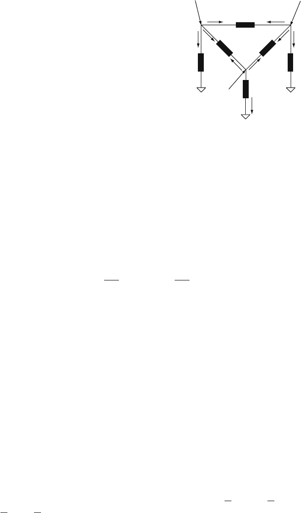
Fig. 5.8 Circuit diagram
representing three nodes
connected to each other and
ground through impedances
Z
nm
.TheI
n
(t) represent
external currents impressed
on the nodes, and the
V
n
(t) represent the resulting
voltages
V
1
(t)
Z
12
Z
23
0
Z
2
Z
11
0
Z
13
0
Z
33
V
2
(t)
V
3
(t)
I
1
(t)
I
2
(t)
I
3
(t)
through Z
nm
and the current I
nn
flowing between node n and ground through Z
nn
are
defined by
I
nm
(s)=[V
n
(s) −V
m
(s)]/Z
nm
(s) and I
nn
(s)=V
n
(s)/Z
nn
(s). (5.24)
On every node, the sum of all currents must be zero, which gives
I
n
−I
nn
−
∑
m=n
I
nm
= 0 → I
n
=
∑
m
y
nm
V
m
, (5.25)
where we have defined the admittance matrix y
nm
of the circuit as
y
nn
=
∑
m
1
Z
nm
y
nm
= −
1
Z
nm
n = m. (5.26)
The voltages on the nodes, resulting from the impressed currents, are therefore
given by
V
n
(s)=
∑
m
z
nm
(s)I
m
(s) z
nm
(s)=y
−1
nm
(s). (5.27)
The matrix z
nm
is the inverse of the admittance matrix and is called the impedance
matrix of the circuit.
Up to this point we have understood that there is a linear relationship [Eq. (5.25)
or Eq. (5.27)] between the currents I
n
(t) impressed on the nodes of the network
(Fig. 5.8) and the resulting potentials V
n
(t) on the nodes. What we finally want
to determine are the potentials V
ind
n
(t) induced by a moving charge q between the
electrodes that are part of a network as shown in Fig. 5.9a. In the following we
will find that these voltages are calculated by adding the mutual electrode capaci-
tances to the network from Fig. 5.8 and placing the currents that would be induced
on grounded electrodes as impressed currents to this circuit (Fig. 5.9b). The drift
of charges in gases is slow enough to allow the use of the quasi-electrostatic cal-
culation, meaning that Eq. (5.5) and the reciprocity theorem (5.7) are also valid for
time-dependent charges Q
n
(t) and voltages V
n
(t) at every time t. Following the pro-
cedure of Sect. 5.3, we use a second electrostatic state, where
Q
0
(t)=0, V
1
(t)=V
w
and V
2
(t)=V
3
(t)=0, which gives