Blum W., Riegler W., Rolandi L. Particle Detection with Drift Chambers
Подождите немного. Документ загружается.


136 4 Amplification of Ionization
Table 4.2 Measured Diethorn parameters for various gases
Gas mixture E
min
(
ρ
0
)
Δ
V Refs.
(k V/cm) (V)
Ar(90%)+CH
4
(10%) 48± 323.6±5.4HEN72
Ar(95%)+CH
4
(5%) 45± 421.8±4.4HEN72
CH
4
69± 536.5 ±5.0HEN72
C
3
H
8
100± 429.5±2.0HEN72
He(96%)+(CH
3
)
2
CHCH
3
(4%) 148± 227.6±3.0HEN72
Ar(75%)+Xe(15%)+CO
2
(10%) 51± 420.2±0.3HEN72
Ar(69.4%)+Xe(19.9%)+CO
2
(10.7%) 54.5 ± 4.0 20.3 ±2.5HEN72
Ar(64.6%)+Xe(24.7%)+CO
2
(10.7%) 60± 518.3±5.0HEN72
Xe(90%)+CH
4
(10%) 36.2 33.9 WOL 74
Xe(95%)+CO
2
(5%) 36.6 31.4 WOL 74
CH
4
(99.8%)+Ar(0.2%) 171 38.3 KIS 60
Ar(92.1%)+CH
4
(7.9%) 77.5 30.2 DIE 56
CH
4
(76.5%)+Ar(23.5%) 196 36.2 DIE 56
CH
4
(90.3%)+Ar(9.7%) 21.8 28.3 DIE 56
Ar(90%)+CH
3
CH
2
OH(10%) 62 27.0 DIE 56
CH
4
144 40.3 DIE 56
4.4.2 Dependence of the Gain on the Gas Density
The variation of the gain with the gas density is of particular interest since very
often the chambers are operated at atmospheric pressure and the gas density changes
proportionally to it. From (4.10) and (4.11), a small relative change d
ρ
/
ρ
of the
density can be seen to result in a change of amplification of
dG
G
= −
λ
ln2
Δ
V2
πε
0
d
ρ
ρ
. (4.15)
In practical cases the factor that multiplies d
ρ
/
ρ
ranges between 5 and 8: varia-
tion of the gas pressure causes global variations of the gain that are typically 5 to 8
times larger. Since the gas pressure can be easily monitored these variations can be
corrected for.
4.4.3 Measurement of the Gain Variation with Sense-Wire
Voltage and Gas Pressure
In this section we give some measurements of the variation of the gain with the
sense wire voltage and with the atmospheric pressure. These measurements have
been obtained using prototypes of the ALEPH TPC that had a cell geometry as
described in Sect. 3.2.
Figure 4.10 shows a plot of the gain as a function of the voltage (cf. (4.14)) using
the Diethorn parameters for an Argon (90%)–CH
4
(10%) mixture (cf. Table 4.2) and
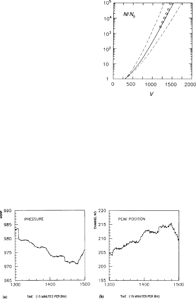
4.4 Amplification Factor (Gain) of the Proportional Wire 137
Fig. 4.10 Gain as a function
of the sense-wire voltage in a
chamber with a cell geometry
as described in Sect. 3.2. Dots
are measurements done with
a model of the ALEPH TPC;
the full line is computed with
(4.14) and Table 4.2; broken
lines show the error margins
introduced by the error in
Table 4.2
assuming atmospheric pressure. The two side-lines show the large uncertainty in
the prediction of the gain owing to the large error (20%) in
Δ
V. The superimposed
experimental points have been measured with a chamber under the same operating
conditions. The agreement is very good.
Figure 4.11 shows the variation of the atmospheric pressure p over a period of
2 days (a) and the corresponding average pulse height measured by the chamber
when detecting the electrons produced in the gas by the absorption of X-rays from
a
55
Fe source (b). One notices how the measured pulse height follows the variations
of the pressure (note the zero-suppressed scales of the two plots). The chamber
was operated in an Argon (90%)–CH
4
(10%) mixture. The sense-wire voltage was
1.4 kV and the field wires were grounded. Using Table 3.5 we can compute the
linear charge density
λ
of the sense wires and from the measured value of
Δ
V
Fig. 4.11 (a) Atmospheric pressure p as a function of the time in a time interval of two days. (b)
Average pulse-height measured by the chamber in the same period. Measurements done with the
ALEPH TPC

138 4 Amplification of Ionization
(cf. Table 4.2) using (4.15) we predict that
dG
G
= −(6.7±1.5)
dp
p
.
Inspecting Fig. 4.11 a we read an overall change of pressure of 0.8% and predict a
change of gain of −(5.5 ±1.2)%, in agreement with the variation (−4%) shown in
Fig. 4.11b.
4.5 Local Variations of the Gain
Equation (4.12) shows that the gain depends on the local charge density of the wire
λ
. A relative change d
λ
/
λ
, as may result from geometrical imperfections of a wire
chamber, from fluctuations of the supply voltage, or from space charge near the wire
will change the amplification by the factor [cf. (4.12)]
dG
G
=
lnG +
λ
ln2
Δ
V2
πε
0
d
λ
λ
. (4.16)
In practical cases the two factors in the parentheses of the previous equation are of
the same order of magnitude and their sum lies in the range 10–20: the local relative
variations of the charge density cause local relative variations of the gain that are
typically 10–20 times greater.
In Sect. 3.2 we saw how the linear charge density
λ
depends on the potentials
and on the geometry of the wire chamber, assuming that there is an ideal geometry.
Real chambers deviate from the ideal geometry: the wires are not infinite and we
can expect changes in the charge density in the region close to the wire supports.
Moreover, the mechanical components of the chamber have small construction im-
perfections, which can induce local changes in the charge density along the wire.
The mathematical solution of the electrostatic problem is not simple because as
soon as we introduce variations in the ideal geometry we lose the symmetry of the
boundary conditions.
In drift chambers that are operated in high-density particle fluxes there is another
problem: the local charge density on the wire seen by ionization electrons when they
reach the wire can be modified by the presence of the ions which were produced in
a previous avalanche and still are drifting inside the drift cell.
4.5.1 Variation of the Gain Near the Edge of the Chamber
In wire chambers the gain usually drops to zero near the support frame. This be-
haviour depends on the details of the geometry and extends over a region of the
wire comparable to the distance between the sense-wire grid and the cathode plane.
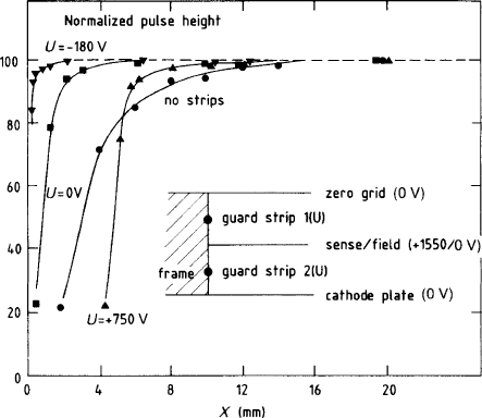
4.5 Local Variations of the Gain 139
Fig. 4.12 Measured pulse heights of wire signals created by a laser beam near the wire support
frame as a function of the distance between the frame and the laser beam. Guard strips can extend
the sensitive length of the wire. The distance between neighbouring grids was 4 mm [BRA 85]
Figure 4.12 from [BRA 85] shows the relative variation of the gain near the edge of
a wire chamber.
The dependence of the wire gain on the distance from the chamber edge can be
modified by the addition of field correction strips [BRA 85], [AME 86c], which can
be trimmed to an appropriate voltage to modify the electric field in the region of the
frame and to obtain a more uniform charge density (see Fig. 4.12).
4.5.2 Local Variation of the Gain Owing to Mechanical
Imperfections
Here we want to evaluate the extent to which small deviations from the ideal ge-
ometry can affect the charge density on the sense wires, and we refer again to the
example discussed in Sect. 3.2. The problem has been extensively studied by Erskine
[ERS 72], and we refer to his paper for a general discussion.
The order of magnitude of the charge variation induced by some imperfections of
the chamber can be obtained using the general formulae of Sect. 3.2: this is possible
for imperfections that can be approximated to a large extent as a global variation of
the geometry of the chamber. For example, the effect of a bump in the cathode plane
can be evaluated from the global effect of a reduction of the distance between the
sense-field grid and the cathode plane.
In the following we refer to the notation of Sect. 3.2 and to the geometry sketched
in Fig. 3.4. Equation (3.39) gives the potentials of the electrodes as a function of

140 4 Amplification of Ionization
their charges and of the matrix of the potential coefficients A:
V = A
σ
, (4.17)
where the
σ
i
=
λ
i
/S
i
are the linear charge densities on the wires of each grid divided
by the pitch of the grid. A change in the geometry of the wire chamber induces a
change in the matrix. Differentiating (4.17) with the fixed values of the potential V,
we obtain
Ad
σ
= −dA
σ
,
where d
σ
is the vector of the charge-density variations and dA is the matrix of
the variations in the potential coefficients induced by a particular change in the
geometry of the chamber. Using the previous equation, we obtain
d
σ
= −A
−1
dA
σ
. (4.18)
As a first example we calculate the charge-density variation induced by a dis-
placement of the cathode plane. The matrix dA can be calculated by differentiating
(3.41) with respect to z, noting that the effect of a displacement dz of the cathode
plane changes z
1
and z
2
by the same amount (cf. Fig. 3.4):
dA = −
dz
ε
0
⎛
⎜
⎜
⎝
111
111
111
⎞
⎟
⎟
⎠
. (4.19)
From (4.18),
d
σ
=
dz
ε
0
A
−1
⎛
⎜
⎜
⎝
σ
s
+
σ
F
+
σ
z
σ
s
+
σ
F
+
σ
z
σ
s
+
σ
F
+
σ
z
⎞
⎟
⎟
⎠
. (4.20)
In the approximations of Sect. 3.2 the quantity
σ
s
+
σ
F
+
σ
z
is the charge density
on the cathode plane. The charge-density variation d
σ
induced by a displacement
of the cathode plane vanishes if there are no charges on the plane. In the particular
geometry of the example considered in Sect. 3.2, we obtain:
d
σ
s
=(70m)
−1
dz(
σ
s
+
σ
F
+
σ
z
).
As another example we now compute the charge variation induced by a change in
the sense-wire diameter. Differentiating (3.41) with respect to the sense-wire radius
r
s
yields
dA = −
s
1
2
πε
0
dr
s
r
s
⎛
⎜
⎜
⎝
100
000
000
⎞
⎟
⎟
⎠
, (4.21)
4.5 Local Variations of the Gain 141
and
d
σ
= −
s
1
2
πε
0
dr
s
r
s
A
−1
⎛
⎜
⎜
⎝
σ
s
0
0
⎞
⎟
⎟
⎠
. (4.22)
For the particular example considered in Sect. 3.2 we get
d
σ
s
σ
s
= 0.16
dr
s
r
s
.
The effect of the displacement of a single wire is more difficult. In this case we
cannot use (3.41) because it was calculated for a set of symmetric grids, and this
symmetry is lost when a single wire is displaced. We note that in first order the
displacement of a wire does not affect the charge density of the wire itself (again
because of the symmetry), but only that of other wires close to it. The displacement
of a field wire changes the charge density of the two closest sense wires proportion-
ally to its own charge density. If there is no charge density on the field wires, their
displacement does not affect the gain of the chamber.
Table 4.3 shows the gain variations induced by mechanical imperfections in the
geometry of the example discussed here. We have assumed that the setting of the
voltages produces a gain of 10
4
, and using (4.16) we compute the relation between
the relative variation of the gain and the local relative charge-density variation:
dG
G
=(15.9±1.5)
d
σ
s
σ
s
.
The same gain can be obtained for different settings of the sense-wire voltage
(V
s
) and the field-wire voltage (V
F
) that leave the charge density on the sense wire
σ
s
unchanged. Using Table 3.3 we compute the condition of constant gain:
0.25V
s
−0.11V
F
= constant.
The different settings correspond to different values of the ratio
σ
F
/
σ
s
. Again using
Table 3.3 we deduce that if V
F
/V
s
= 0, then
σ
F
/
σ
s
= −0.44, while
σ
F
/
σ
s
= 0 when
V
F
/V
s
= 0.34. As shown in Table 4.3 the ratio
σ
F
/
σ
s
influences the local variations
of the gain that are due to mechanical imperfections.
Table 4.3 Gain variation dG/G induced by mechanical imperfections in the geometry discussed
in Sect. 3.2. A gain of 10
4
is assumed and all displacements (
Δ
) are in mm.
σ
F
/
σ
s
is the ratio
between the charge densities on the field wires and the sense wires
Imperfection dG/G
Bump on the pad plane 0.69
Δ
z(1+
σ
F
/
σ
s
)
Displacement of a field wire 1.1
Δ
x
σ
F
/
σ
s
Displacement of a sense wire 0.2
Δ
x
Variation of the sense wire diameter 2.5
Δ
r/r
142 4 Amplification of Ionization
4.5.3 Gain Drop due to Space Charge
When the avalanche has come to an end, all electrons are collected on the anode and
the space near the wire is filled with the remaining positive ions. We may assume
that in the regime of proportional wire amplification, the amount of charge in the
avalanche is small compared to the charge on the wire (integrated along the wire
over the lateral extent of the avalanche). The positive ions are moving away from
the wire at relatively low speed. With a mobility of a few cm/s per V/cm, a typical
speed near the thin wire (E ∼ 2 ×10
5
V/cm) would be several 10
5
cm/s, and a
hundred times less at a hundred times the radius. The avalanche charge obviously
takes hundreds of microseconds to settle on a cathode several millimetres away.
When there is a continuous particle flow with a much higher frequency than that
corresponding to the ion travel time, we have a stationary situation, and the travel-
ling ions build up a stationary space charge density
ρ
(x) in the chamber volume.
This reduces the electric field close to the wire and therefore the gas gain, which
poses a fundamental limitation on the rate capability of any wire chamber.
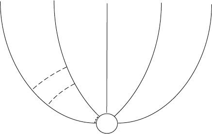
In order to calculate
ρ
we consider in Figure 4.13 a small area A
1
of the wire
surface which shows an electric field E
1
and which releases positive ions of charge
q at a constant rate
ν
. The ions are moving with a velocity of v =
μ
E
1
where
μ
is
the ion mobility. Within a time
Δ
t, the charge Q
1
= q
νΔ
t is entering the volume
V
1
= A
1
v
Δ
t, which results in a charge density of
ρ
1
= Q
1
/V
1
= q
ν
/
μ
E
1
A
1
close to
the wire surface. As the ions are moving away from the wire along the electric field
lines they are passing an equipotential area A
2
in a field E
2
, and the charge density
at this position is
ρ
2
= q
ν
/
μ
E
2
A
2
. From Gauss’ Law we know that E
2
A
2
−E
1
A
1
=
Q/
ε
0
, where Q is the total charge contained in the ‘flux tube’ between A
1
and A
2
.
If the electric field due to the space charge is small compared to the electric field
A1, E1
A2, E2
A3, E3
Fig. 4.13 Anode wire with some field lines (continuous) and some equipotential lines (broken).
The A’s symbolize the areas of the equipotential surfaces between the same field lines that come
from the border of the original area A
1
on the wire surface. The E’s represent the fields on the
equipotential surfaces. As the ions travel along the field lines they become slower by the same
factor as the field lines go apart, resulting in a constant charge density in the volume (‘flux tube’)
filled with ions originating from A
1
4.5 Local Variations of the Gain 143
from the wire, which is usually the case, we may neglect Q and obtain in first order
that
E
1
A
1
= E
2
A
2
and therefore
ρ
1
=
ρ
2
.
We have found the remarkable result that the charge density is constant along the
entire ‘flux tube’ at any distance from the wire. In case the electric field E
1
and
the ion flux
ν
are uniform around the wire surface, which is a common case, we
find a constant charge density in the entire volume that is filled by the field lines
originating from the wire.
For a wire of radius a with a surface field of E
1
, a charge deposit q at a rate of R
per unit length of the wire we therefore find a uniform space charge density of
ρ
=
qR
μ
E
1
2a
π
. (4.23)
Next we investigate the gas gain drop due to the presence of
ρ
. Setting a wire to
potential V
0
amounts to placing a certain charge
λ
on the wire. The charge density
ρ
creates an electric field E
s
(x) which is superimposed on the electric field of the wire
charge
λ
. The resulting potential difference due to
ρ
is
Δ
V =
E
s
(x)ds, where the
path of integration is taken from the wire surface to the cathode. Consequently the
wire charge
λ
is reduced such that its contribution to the potential is V
0
−
Δ
V.The
gain reduction due to the space charge
ρ
is therefore equal to a voltage reduction
of
Δ
V in the absence of space charge. This effective voltage drop of the wires in a
chamber is therefore calculated in first order by removing all wires and calculating
the potential difference between wire positions and cathode due to the charge density
ρ
. We will now discuss two examples.
First we examine a drift tube (cf. Section 3.1) exposed to a particle flux of
Φ
per
unit detector area and a total avalanche charge of q per particle. With R = 2b
Φ
and
the wire surface field of E
1
= V
0
/(aln
b
a
) we find the uniform space charge density
ρ
=
bq
Φ
ln
b
a
πμ
V
0
. (4.24)
In the absence of the wire,
ρ
produces an electric field of E
s
(r)=
ρ
r/2
ε
0
,sothe
potential difference between wire position and tube wall is
Δ
V =
b
0
E
s
(r)dr =
ρ
b
2
/4
ε
0
=
b
3
q
Φ
ln
b
a
4
πε
0
μ
V
0
. (4.25)
The voltage drop is proportional to the third power of the tube radius, so a reduction
of the tube radius is the most effective way to increase the rate capability. As an
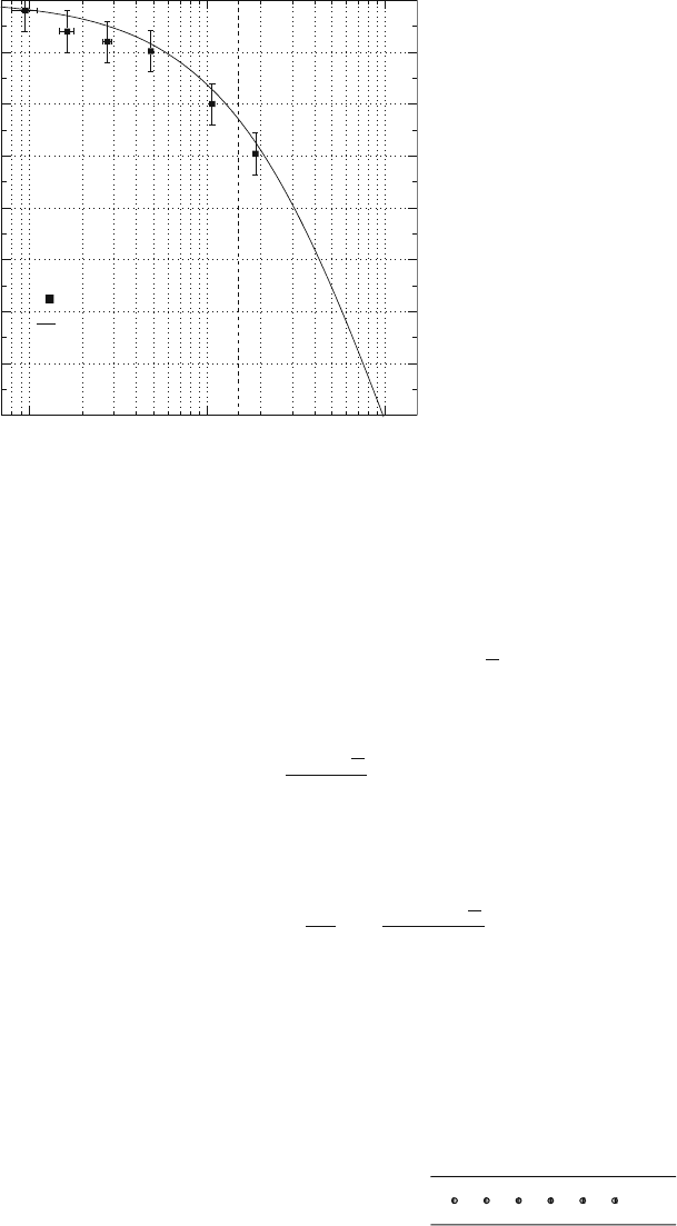
example, Fig. 4.14 shows the gain reduction in the drift tubes of the ATLAS muon
spectrometer [ATL 00]. The measurements are well explained by the theory outlined
above.
As a second example we investigate a wire chamber schematically shown in
Fig. 4.15, where a row of wires with a pitch of s is positioned symmetrically be-
tween two grounded cathode planes at a distance h. Setting all wires to potential V
0
,
144 4 Amplification of Ionization
0.6
0.65
0.7
0.75
0.8
0.85
0.9
0.95
1
10
3
10
2
10
4
Count rate (Hz/cm)
G/G
0
worst ATLAS background rate
including safety factor 5
calculation with average
energy deposit 36
keV
measured gain ratio G/G
0
Fig. 4.14 Calculated and measured gain drop in drift tubes due to photon background in the
ATLAS muon spectrometer. The parameters are b = 15mm, a = 25
μ
m, V
0
= 3170V,
μ
=
0.55cm
2
/Vs. The gain of 2 ×10
4
and primary charge deposit of 1400 electrons/photon yields
q = 4.5pC. A rate of R = 1000Hz/cm results in a voltage drop
Δ
V = −17V and therefore a gas
gain reduction of 10%
the electric field on the wire surface is given by E
1
= V
0
/alog
r
c
a
where r
c
is a length
with an average value of the same order of magnitude as s and h. A particle flux of
Φ
results in R = s
Φ
and we therefore have a uniform charge density of
ρ
=
sq
Φ
ln
r
c
a
2
πμ
V
0
. (4.26)
The electric field due to the charge density
ρ
in the absence of the wires is given by
E(z)=
ρ
z/
ε
0
, and the resulting potential difference is
Δ
V =
h
0
E(z)dz =
h
2
2
ε
0
ρ
=
sh
2
q
Φ
ln
r
c
a
4
πε
0
μ
V
0
. (4.27)
As before, the voltage drop mainly depends on the chamber dimensions s and h
which must be small for a high rate capability of the wire chamber.
One should be aware of the fact that the ion mobility
μ
is often not known very
well due to the presence of charge transfer in the migration of ions. This was elabo-
rated on the last pages of Sect. 2.2.2.
Fig. 4.15 Multiwire
proportional chamber
S
Z = h
Z
= 0
4.6 Statistical Fluctuation of the Gain 145
4.6 Statistical Fluctuation of the Gain
The gain of an avalanche is equal to the number of ion pairs within it divided by
the number of electrons that started the avalanche. In the regime of proportionality,
the average number of electrons produced in the avalanche is proportional to the
number of initial electrons. We are interested in the fluctuation in the number of
electrons that is caused by the random nature of the multiplication process.
We may assume that each initiating electron develops its own small avalanche,
independent of the presence of the others nearby. If we want to know the probabil-
ity distribution of the number N of the ions in the total avalanche we simply sum
over the probability distribution P(n) of the number n of electrons in the individual
small avalanches. The first step is to find an expression P(n), which is done in the
following sections.
If the number k of initiating electrons is large, the central-limit theorem of statis-
tics, which makes a statement about the distribution function F(N) of the sum N,
applies:
N = n
1
+ n
2
+ n
3
+ ...+ n
k
, (4.28)
where each of the independent variables n
i
has the distribution function P(n).Ifthe
mean of P(n) is called
n and the variance is
σ
2
, then the central-limit theorem states
that in the limit of k →∞, F(N) is a Gaussian:
F(N)=
1
S
√
2
π
exp
(
(N −N)
2
/2S
2
)
(4.29)
with
N = kn and S
2
= k
σ
2
. (4.30)
This means that the exact shape of P(n) is not needed for the distribution of
avalanches started by a large number of electrons. On the other hand, P(n) is par-
ticularly interesting for drift chambers where individual ionization electrons have to
be detected, as in ring-imaging (RICH) counters.
Single-electron spectra and avalanche fluctuations in proportional counters have
been measured by Hurst et al., using laser resonant ionization spectroscopy (RIS)
[HUR 78] and by Schlumbohm [SCH 58], whose data are discussed later. A review
of single-electron spectra is given by Genz [GEN 73].
Statistical fluctuations of the gain may be influenced by chemical reactions asso-
ciated with the formation of avalanches. Such deterioration of performance occurs
either through deposits on old wires or through the presence of small contaminations
of the gas. A discussion of these effects is given in Sect. 12.6; we refer especially to
Fig. 12.7. Here we assume that the proportional wire is in an unperturbed working
condition.
4.6.1 Distributions of Avalanches in Weak Fields
In this section we investigate the fluctuation of avalanches started by single elec-
trons in weak electric fields, where the assumption holds that the average distance