Blum W., Riegler W., Rolandi L. Particle Detection with Drift Chambers
Подождите немного. Документ загружается.

106 3 Electrostatics of Tubes, Wire Grids and Field Cages
φ
(U)=−
λ
2
πε
0
ln
sin[(
π
/s)(U −U
0
)]
sin[(
π
/s)(U −
¯
U
0
)]
and the corresponding real potential is
V(x, z)=Re
φ
(U)
= −
λ
4
πε
0
ln
sin
2
[(
π
/s)(x −x
0
)] + sin h
2
[(
π
/s)(z −z
0
)]
sin
2
[(
π
/s)(x −x
0
)] + sin h
2
[(
π
/s)(z + z
0
)]
. (3.34)
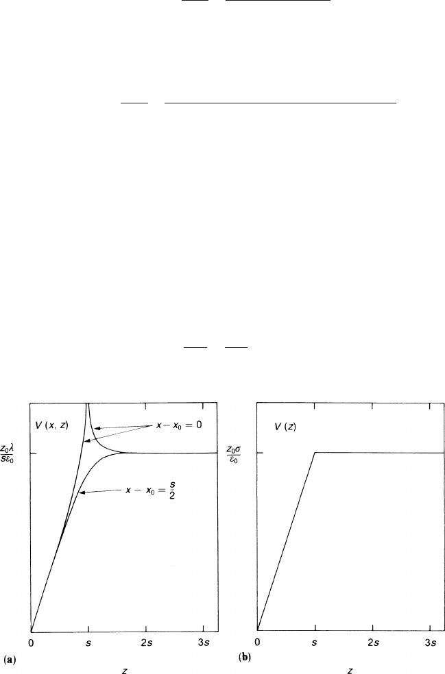
Figure 3.5a shows V (x, z) as function of z at two different values of x. In the chosen
example the grid was placed at z
0
= s. We notice that such a grid behaves almost
everywhere like a simple layer of charge with surface density λ/s. Only in the imme-
diate vicinity of the wires (distances much smaller than the pitch) can the structure
of the grid be seen (compare with Fig. 3.5b, which shows the potential of a simple
layer of charge). Therefore it is possible to superimpose different grids or plane elec-
trodes at distances larger than the pitch without changing the boundary conditions
of the electrostatic problem. We have an example of the general two-dimensional
problem where a potential
φ
that varies periodically in one direction x has every
Fourier component ≈cos(2
π
nx/s) damped along the transverse direction z accord-
ing to the factor e
−2
π
nz/s
. This holds because every Fourier component must satisfy
Laplace’s equation
∂
2
φ
∂
x
2
+
∂
2
φ
∂
z
2
= 0
Fig. 3.5 (a) The potential V (x, z) of a grid of wires situated a distance z
0
from a conducting plane
at x
0
, x
0
+ s,... with pitch s = z
0
and a linear charge density λ per wire. (b) The potential V (z) of
a plane of charge situated a distance z
0
from a conducting plane, with a surface charge density
σ
3.2 Wire Grids 107
outside the wires. The solution is
φ
=
∑
n
C
n
e
−2
π
nz/s
cos(2
π
nx/s),
the C
n
being constants.
At a distance from the grid comparable or larger than the pitch the potential
assumes the value
V(x, z)=
zλ
ε
0
s
for z < z
0
,z
0
−z
s
2
π
,
V(x, z)=
z
0
λ
ε
0
s
for z
0
< z,z −z
0
s
2
π
.
(3.35)
On the surface of the wires the potential assumes the value evaluated at (x−x
0
)
2
+(z −z
0
)
2
= r
2
. We replace in first order of r/s the hyperbolic functions by their
arguments and take for sinh(2
π
z
0
/s) the positive exponential. The potential of the
wire is then
V(wire)=
λz
0
ε
0
s
1−
s
2
π
z
0
ln
2
π
r
s
. (3.36)
This means that the wire grid, although it behaves like a simple sheet with area
charge density λ/s has some ‘transparency’. We could have given the grid a zero
potential and the conducting plane a potential V . Then, beyond the grid the potential
would have been
λ
2
πε
0
ln
2
π
r
s
and not zero as on the grid – some of the potential of the plane behind can be ‘seen
through the grid’. In other words, the potential beyond the grid is different from the
potential on the grid by the difference between the electric field on the two sides of
the grid, multiplied by the length (s/2
π
)ln(2
π
r/s).
The electric field that can be computed from (3.34) is given here for convenience:
E
x
(x,z)=
λ
2s
ε
0
sin
2
π
s
(x −x
0
)
1
A
1
−
1
A
2
,
E
z
(x,z)=
λ
2s
ε
0
$
sinh[(2
π
/s)(z −z
0
)]
A
1
−
sinh[(2
π
/s)(z + z
0
)]
A
2
%
,
where
A
1
= cosh
2
π
s
(z −z
0
)
−cos
2
π
s
(x −x
0
)
,
A
2
= cosh
2
π
s
(z + z
0
)
−cos
2
π
s
(x −x
0
)
.
108 3 Electrostatics of Tubes, Wire Grids and Field Cages
3.2.2 Superposition of the Electric Fields of Several Grids
and of a High-Voltage Plane
Knowing the potential created by one plane grid (3.34) and its very simple form
(3.35) valid at a distance d(d s/2
π
) out of this plane, we want to be able to
superimpose several such grids, in order to accommodate not only the sense wires
but also all the other electrodes: the near-by field and shielding wires and the distant
high-voltage electrode.
In order to be as explicit as possible we will present the specific case of a TPC.
These chambers have more grids than most other volume-sensitive drift chambers,
and the simpler cases may be derived by removing individual grids from the follow-
ing computations.
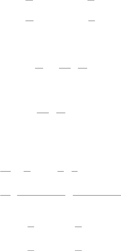
We want to calculate the electric field in a TPC with the geometry sketched in
Fig. 3.6. The pad plane is grounded, and we have four independent potentials: the
high-voltage plane (V
p
), the zero-grid wire (V
z
), the field wires (V
f
) and the sense
wires (V
s
). We have to find the relations between those potentials and the charge
induced on the different electrodes.
Since the distance d between the grid planes satisfies the condition d s/2
π
,
the total electric field is generally obtained by superimposing the solution of each
grid. This assumes that all the wires inside a single grid are at the same potential,
but it is not the case for the sense-wire and field-wire grids where the sense wires
and the field wires are at different potentials and the two grids are at the same z.In
this case the superposition is still possible owing to the symmetry of the geometry:
the potential induced by the sense-wire grid on the field wires is the same for all the
field wires and vice-versa.
The potential induced by the sense-wire grid on the field wires can easily be
computed because the field-wire grid and the sense-wire grid have the same pitch.
Evaluating formula (3.34) at the position of any field wire we find that
V
x
0
+
s
1
2
+ ks
1
,z
1
=
λ
s
2
πε
0
ln
cosh
2
π
z
1
s
1
≈
λ
s
z
1
ε
0
s
1
−
λ
s
2
πε
0
ln2. (3.37)
Fig. 3.6 Basic grid
geometry of a TPC: The
sense-wire/field-wire plane
is sandwiched between
two grounded planes – the
zero-grid-wire plane and the
pad plane. The high-voltage
planeisalargedistanceaway
from them

3.2 Wire Grids 109
We can now use (3.35), (3.36) and (3.37) to calculate the potential of each elec-
trode as the sum of the contributions of the charges induced on each grid and on the
high-voltage plane:
V
s
=
λ
s
z
1
ε
0
s
1
1−
s
1
2
π
z
1
ln
2
π
r
s
s
1
+
λ
f
z
1
ε
0
s
1
1−
s
1
2
π
z
1
ln2
+
λ
z
z
1
s
2
ε
0
+
σ
p
z
1
ε
0
,
V
f
=
λ
s
z
1
ε
0
s
1
1−
s
1
2
π
z
1
ln2
+
λ
f
z
1
ε
0
s
1
1−
s
1
2
π
z
1
ln
2
π
r
f
s
1
+
λ
z
z
1
s
2
ε
0
+
σ
p
z
1
ε
0
,
(3.38)
V
z
=
λ
s
z
1
s
1
ε
1
+
λ
f
z
1
s
1
ε
0
+
λ
z
z
2
ε
0
s
2
1−
s
2
2
π
z
2
ln
2
π
r
z
s
2
+
σ
p
z
2
ε
0
,
V
p
=
λ
s
z
1
s
1
ε
0
+
λ
f
z
1
s
1
ε
0
+
λ
z
z
2
s
2
ε
0
+
σ
p
z
p
ε
0
,
where
σ
p
is the surface charge density on the high-voltage plane, λ
s
,λ
f
,λ
z
are the
charges per unit length on the wires, and r
s
,r
f
,r
z
are the radii of the wires.
We can define a surface charge density
σ
, for each grid, as the charge per unit
length, divided by the pitch (λ
i
/s
i
), and (3.38) can be written as
⎛
⎜
⎜
⎝
V
s
V
f
V
z
V
p
⎞
⎟
⎟
⎠
= A
⎛
⎜
⎜
⎝
σ
s
σ
f
σ
z
σ
p
⎞
⎟
⎟
⎠
, (3.39)
where A is the matrix of the potential coefficients. The matrix A can be inverted to
give the capacitance matrix (this is the solution of the electrostatic problem):
⎛
⎜
⎜
⎝
σ
s
σ
f
σ
z
σ
p
⎞
⎟
⎟
⎠
= A
−1
⎛
⎜
⎜
⎝
V
s
V
f
V
z
V
p
⎞
⎟
⎟
⎠
. (3.40)
Once the capacitance matrix A
−1
is known we can calculate the charges in-
duced on each electrode for any configuration of the potentials. The electric field is
given by the superposition of the drift field with the fields of all the grids, given by
(3.38).
In normal operating conditions the electric field in the amplification region is
much higher than the drift field. In this case λ
s
/s
1
|
σ
p
| and the charge induced on
the high-voltage plane can be approximated by
σ
p
=
ε
0
V
p
−V
z
z
p
−z
2
.
Then the matrix A of (3.39) can be reduced to a 3×3 matrix, neglecting the last row
and the last column,

110 3 Electrostatics of Tubes, Wire Grids and Field Cages
Table 3.2 Matrix of the potential coefficients (m
2
/farad) referring to the grids s, f and z in the
standard case
A = 1.13×10
8
⎛
⎜
⎜
⎝
6.64 3.56 4.00
3.56 5.62 4.00
4.00 4.00 8.28
⎞
⎟
⎟
⎠
A =
1
ε
0
⎛
⎜
⎜
⎜
⎜
⎜
⎝
z
1
−
s
1
2
π
ln
2
π
r
s
s
1
z
1
−
s
1
2
π
ln2 z
1
z
1
−
s
1
2
π
ln2 z
1
−
s
1
2
π
ln
2
π
r
f
s
1
z
1
z
1
z
1
z
2
−
s
2
2
π
ln
2
π
r
z
s
2
⎞
⎟
⎟
⎟
⎟
⎟
⎠
. (3.41)
Tables 3.2 and 3.3 give the coefficients of the matrix A of (3.41) and of its inverse
in a standard case:
z
1
= 4mm, z
2
= 8mm, s
1
= 4mm, s
2
= 1mm,
r
s
= 0.01mm, r
f
= r
z
= 0.05mm.
Using (3.38) we can now compute the potential of the high-voltage plane when
it is uncharged (
σ
p
= 0):
V
p
= V(∞)=
σ
s
z
1
ε
0
+
σ
f
z
1
ε
0
+
σ
z
z
2
ε
0
. (3.42)
The electric field in the drift region is zero.
In order to produce a drift field E we have to set the high-voltage plane at a
potential
V
p
= −E(z
p
−z
2
)+V (∞). (3.43)
(E is defined positive and is the modulus of the drift field.)
3.2.3 Matching the Potential of the Zero Grid and of the Electrodes
of the Field Cage
When we set the potential of the high-voltage plane V
p
to the value defined by (3.43),
the potential in the drift region (z−z
2
s
2
/2
π
) is given by
Table 3.3 Capacitance Matrix (farad/m
2
) referring to the grids s, f and z in the standard case
A
−1
= 8.85 ×10
−9
⎛
⎜
⎜
⎝
0.25 −0.11 −0.07
−0.11 0.32 −0.10
0.07 −0.10 0.21
⎞
⎟
⎟
⎠
3.2 Wire Grids 111
V(z)=−E(z −z
2
)+V(∞). (3.44)
Using equations (3.41) and (3.42) one can show that
V
z
= V(∞) −
s
2
2
πε
0
σ
z
ln
π
r
z
s
2
,
and (3.44) can be written as
V(z)=−E(z −z
2
)+V
z
+
s
2
2
πε
0
σ
z
ln
2
π
r
z
s
2
. (3.45)
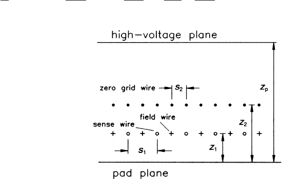
Figure 3.7 shows V(z) −V
z
as function of z −z
2
in the geometry discussed in
the previous section with V
s
= 1300V,V
g
= V
z
= 0 and with a superimposed drift
field of 100 V/cm. We notice that in this configuration the equipotential surface of
potential V
z
is shifted into the drift region by about 2 mm. This effect has to be taken
into account when the potential of the electrodes of the field cage has to be matched
with the potential of the zero grid and when one has to set the potential of the gating
grid (see Sect. 3.3.2).
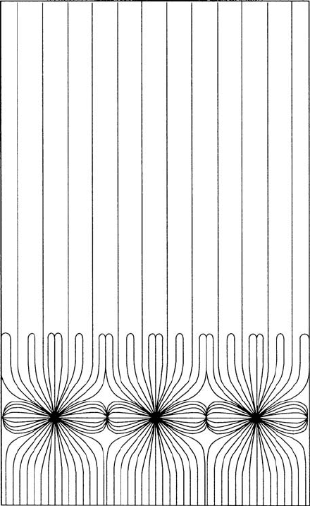
After the adjustment of all the potentials on the grids and the high-voltage plane
the field configuration is established. We show in Fig. 3.8 the field lines for the typ-
ical case of a TPC corresponding to Fig. 3.6 with z
1
= 4mm, z
2
= 8mm, s
1
=
4mm, s
2
= 1mm, r
s
= 0.01mm, r
f
= r
z
= 0.05mm, V
s
= 1300V, V
f
= V
z
=
0, E
p
= 100V/cm. One observes that the drift region is filled with a very uniform
Fig. 3.7 Potential in the
region of the zero grid as a
function of z in presence of
the drift field; example as
discussed in the text
112 3 Electrostatics of Tubes, Wire Grids and Field Cages
Fig. 3.8 Field lines for the typical case of a TPC with electrodes as in Fig. 3.6
(z
1
= 4mm, z
2
= 8mm, s
1
= 4mm, s
2
= 1mm, r
s
= 0.01mm, r
f
= r
z
= 0.05mm, V
s
=
1300V, V
f
= V
z
= 0, E
p
= 100V/cm)
field, but also in the amplification region we find homogeneous domains as expected
from (3.35). The electric field lines reach the sense wires from the drift region along
narrow paths.
3.3 An Ion Gate in the Drift Space
It is possible to control the passage of the electrons from the drift region into the
amplification region with a gate, which is an additional grid (‘gating grid’), located
inside the drift volume in front of the zero grid and close to it. This is important
when the drift chamber has to run under conditions of heavy background.
3.3 An Ion Gate in the Drift Space 113
In this section we deal with the principal (electrostatic) function of the ion gate
and how it is integrated into the system of all the other electrodes. Chapter 9 is
devoted to a discussion of the behaviour of ion gates and their transparency under
various operating conditions, including alternating wire potentials, and magnetic
fields.
The potential of the wires of the gating grid can be regulated to make the grid
opaque or transparent to the drifting electrons. In this section we neglect the effect
of the magnetic field and assume that the electrons follow the electric field lines.
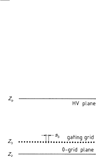
In the approximation that the electric field in the amplification region is much
higher than the drift field, the variation of the potentials of the gating grid will not
change appreciably the charge distribution on the electrodes in the amplification re-
gion, and we can schematize the gating grid as a grid of wires placed in between two
infinite plane conductors: the high-voltage plane and the zero grid. The geometry is
sketched in Fig. 3.9.
3.3.1 Calculation of Transparency
If the electrons follow the electric field lines we can compute the transparency T ,
i.e. the fraction of field lines that cross the gating grid, from the surface charge on
the high-voltage plane and on the gating grid:
T = 1 −
σ
+
g
|
σ
p
|
, (3.46)
where
σ
p
is the surface charge density on the high-voltage plane (negative) and
σ
+
g
is the surface charge density of positive charges on the gating grid.
If we approximate the wires of the grid by lines of charge λ per unit length, the
surface charge density on the grid is simply λ/s, and the condition of full trans-
parency is
λ ≤ 0.
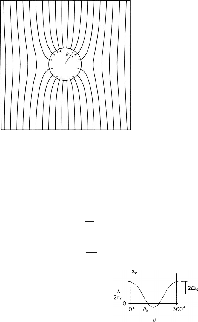
This approximation is no longer correct when the absolute value of λ is so small
that we have to consider the variation of charge density over the surface of the
wire. A wire ‘floating’ in an external electric field E is polarized by the field, which
Fig. 3.9 Scheme for the
inclusion of the gating grid
114 3 Electrostatics of Tubes, Wire Grids and Field Cages
Fig. 3.10 Electric field lines near an uncharged wire floating in a homogenous field
produces a surface charge density
σ
D
on the wire. It depends on the azimuth (see
Fig. 3.10):
σ
D
= 2E
ε
0
cos
θ
, (3.47)
where
θ
is the angle between E and the radius vector from the centre to the surface
of the wire [PUR 63].
In the general case the wire has, in addition to this polarization charge, a linear
charge λ. The total surface charge density on the wire is
σ
w
=
λ
2
π
r
+ 2E
ε
0
cos
θ
, (3.48)
r being the radius of the wire. An illustration is Fig. 3.11. When
|λ|
4
πε
0
Er
Fig. 3.11 Dependence on
azimuth of the surface charge
density
σ
w
located on the
gating grid wire
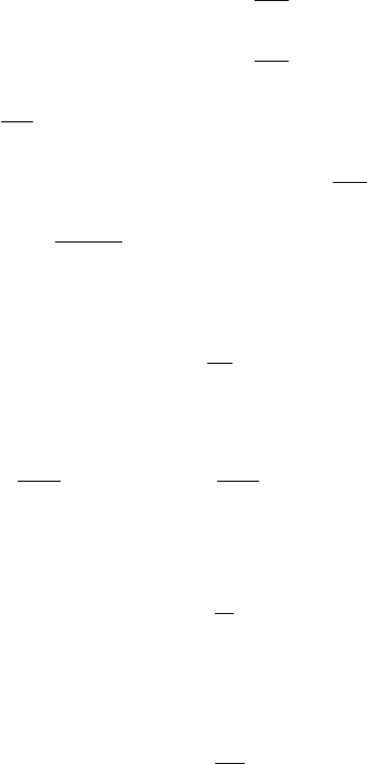
3.3 An Ion Gate in the Drift Space 115
the polarization effect can be neglected. This is the case of the zero-grid, sense and
field wires, as discussed in the previous section.
There may be both positive and negative charges on the wires of the gating grid.
In order to calculate T we must now count the positive charges only. This can be
done using (3.48):
λ
+
= 0 when
λ
2
π
r
< −2E
ε
0
,
λ
+
= λ when
λ
2
π
r
> 2E
ε
0
,
λ
+
=
λ
θ
0
π
+ 4E
ε
0
rsin
θ
0
(3.49)
when −2E
ε
0
<
λ
2
π
r
< 2E
ε
0
,
θ
0
= arccos
−λ
4
πε
0
Er
and the surface charge density of positive charge on the gating grid is
σ
+
g
=
λ
+
s
3
. (3.50)
Using (3.46) and (3.50) we obtain the condition for full transparency in the gen-
eral case:
λ
g
2
π
r
g
≤−2E
ε
0
or
σ
g
2
π
r
g
s
3
≤−2E
ε
0
. (3.51)
In the limiting condition of full transparency, the electric field between the gating
grid and the zero-grid increases by a factor
1+ 4
π
r
g
s
3
with respect to the drift field.
Using (3.50) and (3.50) we can calculate the transparency in the special case of
σ
g
= 0:
T = 1 −
4r
g
s
3
.
The opacity of the gating grid in this configuration is twice the geometrical opac-
ity. To illustrate the situation of limiting transparency the field lines above and below
the fully open gate are displayed in Fig. 3.12a,b.
The drift field lines for our standard case are shown in Fig. 3.13a,b. We observe
that the drifting electrons arrive on a sense wire on one of four roads through the
zero grid – a consequence of the ratio of s
1
/s
3
= 4.
In order to compute the transparency as a function of the gating-grid potential we
have to calculate the capacity matrix. Following the scheme of Sect. 3.2 we obtain