Blum W., Riegler W., Rolandi L. Particle Detection with Drift Chambers
Подождите немного. Документ загружается.

96 2 The Drift of Electrons and Ions in Gases
[TON 55] L. Tonks, Particle transport, electric currents and pressure balance in a magnetically
immobilized plasma, Phys. Rev. 97, 1443 (1955)
[WAG 67] E.B. Wagner, F.J. Davies and G.S. Hurst, Time-of-flight investigations of electron
transport in some atomic and molecular gases. J. Chem. Phys. 47, 3138 (1967)

Chapter 3
Electrostatics of Tubes, Wire Grids
and Field Cages
The electric field in a drift chamber must provide two functions: drift and amplifi-
cation. Whereas in the immediate vicinity of the thin proportional or ‘sense’ wire
the cylindrical electric field provides directly the large field strengths required for
charge amplification, the drift field must be created by a suitable arrangement of
electrodes that are set at potentials supplied by external voltage sources. It is true
that drift fields have also been created by depositing electric charges on insulators –
such chambers are described in Sect. 11.4 – but we do not treat them here. Charge
amplification is not necessarily confined to proportional wires. It has also been mea-
sured between parallel plates and between a wire mesh and a metal plate as well as
in the tiny holes in a plate coated on both sides with the metal layers of a condenser.
In fact these MICROMEGA and GEM counters seem to have a promising future
[FAB 04].
There is a large variety of drift chambers, and they have all different electrode
arrangements. An overview of existing chambers is given in Chap. 11, where we
distinguish three basic types. In the volume-sensitive chambers (types 2 and 3) the
functions of drift and amplification are often more or less well separated, either by
special wire grids that separate the drift space from the sense wire or at least by
the introduction of ‘field’ or ‘potential’ wires between the sense wires. The drift
field, which fills a space large compared to the amplification space, then has to be
defined at its boundaries; these make up the ‘field cage’. For a uniform field, the
electrodes at the boundaries are at graded potentials in the field direction and at
constant potentials orthogonal to it.
Also the area-sensitive chambers (type 1) have often been built with ‘potential’
or ‘field-shaping’ wires to provide a better definition and a separate adjustment of
the drift field. In this chapter we want to discuss some elements that are typical for
the volume-sensitive chambers with separated drift and amplification spaces: one or
several grids with regularly spaced wires in conjunction with a field cage. Although
directly applicable to a time projection chamber (TPC), the following considerations
will also apply to many type 2 chambers.
Electrostatic problems of the most general electrode configuration are usually
solved by numerical methods, for example using relaxation techniques [WEN 58].
W. Blum et al., Particle Detection with Drift Chambers,97
doi: 10.1007/978-3-540-76684-1
3,
c
Springer-Verlag Berlin Heidelberg 2008
98 3 Electrostatics of Tubes, Wire Grids and Field Cages
Computer codes exist for wire chamber applications [VEN 08]. In this chapter we
develop analytical methods taking advantage of simple geometry, in order to es-
tablish the main concepts. A classic treatment is found in Morse and Feshbach
[MOR 53].
The simplest device for the measurement of drift time is the drift or proportional
tube. This name refers to the original, proportional mode of amplification, but the
device can also be used beyond the proportional mode, see Sect. 4.2. In its ideal form
it is a circular cylindrical tube with a wire in the centre. As we have in mind to also
describe deviations from the ideal form which arise in practice we will approach the
electrostatics of a tube in a slightly generalized way.
3.1 Perfect and Imperfect Drift Tubes
Deviations from the ideal geometry of two concentric circular cylinders are caused
by displaced wires or deformed walls. In this section we discuss the electric field
arising in a circular right cylinder with the wire off-centre. Since we are dealing
with relatively small deviations our method is a first-order perturbation calculation
of the linear deviation.
The solution of Laplace’s equation
∇
2
Φ
= 0 (3.1)
for the potential
Φ
in the charge-free space between two conductors is found by
separation of variables. In cylindrical coordinates we write
Φ
(r,
ϕ
,z)=R(r)
φ
(
ϕ
)Z(z)
1
rR
∂
∂
r
r
∂
R
∂
r
+
1
r
2
φ
∂
2
φ
∂ϕ
2
+
1
Z
∂
2
Z
∂
z
2
= 0. (3.2)
Assuming Z(z)=const = 1, we equate the second term to the constant −
ν
2
so that
d
2
φ
d
ϕ
2
= −
ν
2
φ
,
whose solutions are
φ
(
ϕ
)=C
ϕ
cos
νϕ
+C
ϕ
sin
νϕ
if
ν
= 0
φ
(
ϕ
)=C
ϕ
ϕ
+C
ϕ
if
ν
= 0. (3.3)
The C’s are constants to be determined by the boundary conditions. The radial part
becomes the Euler-Cauchy equation
r
d
dr
r
dR
dr
−
ν
2
R = 0. (3.4)

3.1 Perfect and Imperfect Drift Tubes 99
If
ν
= 0, the solution is given by
R(r)=C
r
lnr +C
r
. (3.5)
3.1.1 Perfect Drift Tube
The potential between two coaxial cylinders is a straight application of Eq. (3.5).
When the outer cylinder (radius b) is on ground, and the wire (radius a) on positive
potential U, one determines the coefficients to be given by C
ϕ
= 0, C
r
= −C
r
lnb
and C
r
C
ϕ
ln(a/b)=U, so that
Φ
=
U
ln(a/b)
ln(
r
b
). (3.6)
The electric field is directed radially outwards, and
E
r
= −
∂Φ
∂
r
=
U
ln(b/a)
1
r
. (3.7)
Another way to calculate E
r
is using Gauss’ theorem according to which
E
r
=
λ
2
πε
0
1
r
(3.8)
where λ is the linear charge density on the wire; the value of
ε
0
is 8.854 ·10
−12
As/Vm. Therefore the capacitance per unit length of tube is given by
C =
λ
U
=
2
πε
0
ln(b/a)
.
3.1.2 Displaced Wire
Solution of the Electrostatic Problem
Let the wire be displaced from the tube centre by the distance d in the negative y-
direction (Fig. 3.1). The wire defines the centre of the coordinate system so that the
first boundary condition is
Φ
(a)=U, independent of
ϕ
. (3.9)
We must express the second boundary by the radius vector as a function of
ϕ
.The
exact expression is
ρ
= d sin
ϕ
+ b
"
(1−(d
2
/b
2
)(1−sin
2
ϕ
),
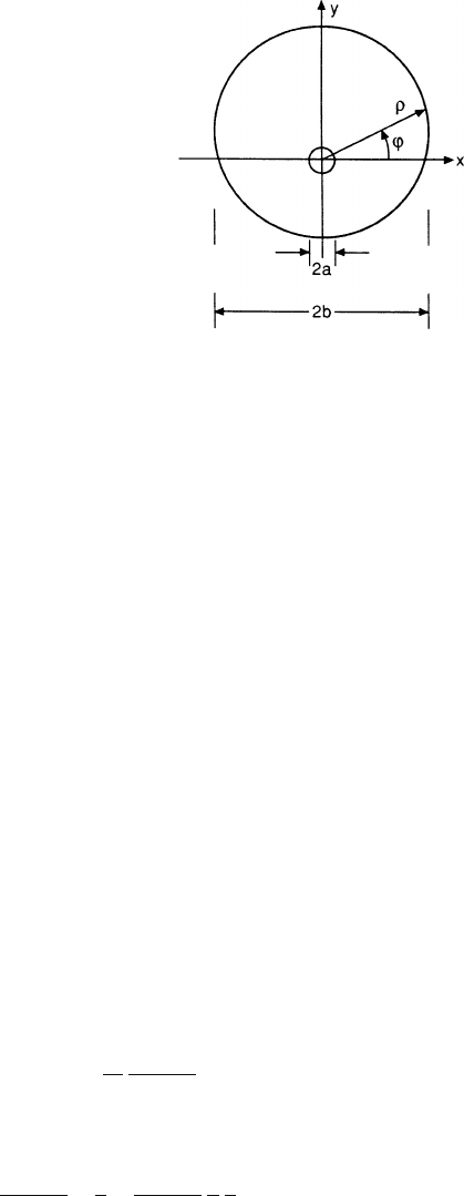
100 3 Electrostatics of Tubes, Wire Grids and Field Cages
Fig. 3.1 Geometry of
displaced wire
but we are only interested in small wire displacements. To first order in d/b we have
the boundary at
ρ
= b+ d sin
ϕ
, (3.10)
and the second boundary condition is
Φ
(
ρ
)=0. (3.11)
Now we must determine the various coefficients using (3.9) and (3.11). To the first
order in d/b we have solutions for
ν
= 0 and
ν
= 1, and the most general solution is
Φ
=(C
0
r
lnr +C
0
r
)C
0
ϕ
+(C
1
r
r +C
1
r
/r)(C
1
ϕ
cos
ϕ
+C
1
ϕ
sin
ϕ
). (3.12)
Inserting (3.9), we have to require
C
1
r
a +C
1
r
/a = 0, (3.13)
which implies that C
1
r
can be neglected against C
1
r
for the entire space except in
the immediate vicinity of the wire surface.
When inserting (3.11) and (3.10) into (3.12) we make use of the relation
ln(b + d sin
ϕ
)=lnb +(d/b) sin
ϕ
,
which holds to first order in d/b. This determines the constants C
0
r
, C
0
r
and C
0
ϕ
as
in the case (3.6) of the perfect tube. Comparing factors that multiply the sin
ϕ
-terms,
we find
C
0
ϕ
C
0
r
(d/b)+C
1
r
bC
1
ϕ
= 0
or
C
1
r
C
1
ϕ
= −
d
b
2
U
ln(a/b)
(3.14)
whereas C
1
ϕ
= 0. This produces the solution, in first order of (d/b), equal to
Φ
(r,
ϕ
)=
U
ln(a/b)
ln
r
b
−
U
ln(a/b)
d
b
r
b
sin
ϕ
. (3.15)
3.1 Perfect and Imperfect Drift Tubes 101
The perturbing potential
Φ
1
caused by the wire displacement is given by the
second term. Using y = rsin
ϕ
, the field perturbation is calculated to be
(E
1
)
y
= −
∂Φ
1
∂
y
= −
U
ln(b/a)
d
b
2
(3.16)
(E
1
)
x
=(E
1
)
z
= 0. (3.17)
It describes a constant field directed towards negative y, whose magnitude is d/b
times the value of the unperturbed field (3.7) at the wall.
For the purpose of calculating the electrostatic force on the wire (see further
down) we also record the value of (E
1
)
y
on the wire surface (r = a). Starting
from (3.13) without the previous simplification C
1
r
= 0, the correct perturbation
potential is
Φ
1
(r,
ϕ
)=
−U
ln(a/b)
d
b
2
(r −
a
2
r
)sin
ϕ
. (3.18)
The field in y-direction equals
(E
1
(a))
y
= −
∂Φ
1
∂
y
evaluated at r = a
= −
U
ln(b/a)
2d
b
2
sin
2
ϕ
Averaging over
ϕ
we have an extra field on the wire surface equal to
(E
1
(a))
y
= −
U
ln(b/a)
d
b
2
(3.19)
The average extra field on the wire surface is as large as the field perturbation (3.16),
(3.17) throughout the volume.
Gravitational Sag
The main reason for wire displacement is the weight of the wire. Even when strung
with a pulling force T close to the breaking limit, wires in several metre long tubes
will experience a gravitational sag that is large in comparison with the achievable
accuracy of drift tubes.
In order to derive a formula for the amount of bowing we introduce the coordi-
nates y (downwards) and x (horizontal). We note that on every length element dx the
weight of the wire is
ρ
g
σ
dx (3.20)
(
ρ
= density,
σ
= cross sectional area of the wire, g = 981cm/s
2
). It must be com-
pensated by the vertical component of the tension at this point, which is equal to the
difference of the slopes at the two ends of the interval dx, multiplied by the pulling
force T:
−T[y
(x + dx) −y
(x)] (3.21)

102 3 Electrostatics of Tubes, Wire Grids and Field Cages
where the primes denote the first derivative. In this approximation we have assumed
that the pulling force is the same for all x, the variation due to the weight of the wire
being negligible for practical tubes.
Combining (3.20) and (3.21), one has the differential equation
−y
= C =
ρ
g
σ
/T (3.22)
with the solution
y =(C/2)x
2
+C
1
x +C
2
. (3.23)
Specifying that y = 0atx = ±L/2 determines the coefficients C
1
, C
2
, and the solu-
tion becomes
y =
C
2
L
2
4
−x
2
. (3.24)
The point of the maximum excursion is the sagitta, equal to
s = y(0)=
CL
2
8
=
ρ
g
σ
L
2
8T
. (3.25)
It is proportional to the inverse of the mechanical tension. If the tension is in-
creased the sagitta is reduced, but the tension cannot be arbitrarily increased since
non-elastic deformations take place. The maximum pulling force T
c
that can be
applied to a wire is proportional to its cross section, and the ratio T
c
/
σ
is con-
stant (except for very thin wires). The minimum achievable sagitta of a wire of
given length is independent of the wire cross section. The values of the critical ten-
sion and typical sagittas for 100-cm-long wires of different materials are shown in
Table 3.1. Usually the wires are strung to a tension close to the critical one in or-
der to reduce the sagging. Inspecting Table 3.1 we notice that among the various
materials, tungsten is the one that allows the smallest sagittas but at the expense
of quite a large tension, for a given diameter of the wire. Since the tension of the
wires is held by the endplates of the chamber, a large tension requires stiff end-
plates. In the design of a chamber one usually compromises between these two
parameters.
If the sagitta of long wires cannot be constructed to be small one may be obliged
to control its size within small tolerances. A practical way of doing this is by mea-
suring the oscillation frequency of the wire. The frequency f
1
of the lowest mode of
the elastic string is
Table 3.1 Maximum stresses before deformation of typical wire materials and corresponding
sagittas for 1-m-long wires
Material T
c
/
σ
(kg/mm
2
) Sagitta (μm) of a 100 cm long wire
strung at T
c
Al 4...16 21...84
Cu 21...37 30...53
Fe 18...25 39...54
W 180...410 6...13
3.1 Perfect and Imperfect Drift Tubes 103
f
1
=
1
2L
#
T
ρσ
. (3.26)
Inserting (3.25) into (3.26) produces the simple relation
f
2
1
=
g
32s
. (3.27)
Electrostatic Force on the Sagged Wire
The displacement of the wire creates an average field (3.19) which acts on the
electric charge of the wire and produces a force which tends to increase the dis-
placement. The differential equation (3.22) needs to be complemented by a term
which represents the electrostatic force per unit wire length. This is given by the
product
λ·
(E
1
(a))
y
where λ is given by (3.8) in terms of the unperturbed field, and (E
1
(a))
y
is given by
(3.19) and is proportional to the displacement y. The electrostatic force, like grav-
ity, points downwards and leads to a positive term on the right-hand side of (3.22),
whereas y
< 0. Therefore, the differential equation is
y
+ k
2
y +C = 0 (3.28)
with C =
ρ
g
σ
/T and k
2
= 2
πε
0
E
2
0
(b)/T.Thevalueofk is plotted against E
0
(b)
and T in Fig. 3.2.
The general solution of (3.28) is
y = C
1
cos kx+C
2
sin kx−C/k
2
. (3.29)
When specifying y(±L/2)=0, the coefficients C
1
, C
2
are determined, and the so-
lution becomes
y =
C
k
2
1
cos(kL/2)
cos kx−1
. (3.30)
The electrostatic force has changed the form of the wire from the parabola (3.24) to
the cosine function (3.30).
The new sagitta is
s
k
= y(0)=
C
k
2
1
cos(kL/2)
−1
kL1
−→
CL
2
8
(3.31)
This means the electrostatic force has increased the sagitta (3.25) by the factor
s
k
s
=
8
k
2
L
2
1
cos(kL/2)
−1
=
2
q
2
1
cos q
−1
. (3.32)
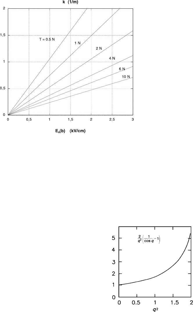
104 3 Electrostatics of Tubes, Wire Grids and Field Cages
Fig. 3.2 Value of the constant k in (3.28) relevant for the electrostatic amplification of the
gravitational sag, as a function of the electric field E
0
(b) at the tube wall, for various wire pulling
forces T
As the product kL approaches the value
π
, the excursion tends to infinity, and
the wire is no longer in a stable position. For example, the gravitational sag of a
wire strung with one N inside a 5 m long tube will be amplified by a factor of
s
k
/s of 1.56 if the field at the wall is E
0
(b)=500V/cm. The point of instability
is reached at E
0
(b)=840V/cm. In Fig. 3.3 we plot s
k
/s as a function of q
2
or
k
2
L
2
/4.
Fig. 3.3 Amplification factor
of the gravitational sag
owing to electrostatic forces,
according to (3.32)
3.2 Wire Grids 105
3.2 Wire Grids
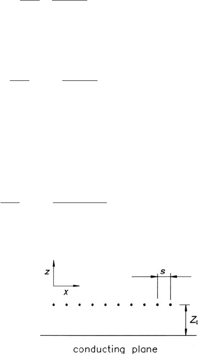
3.2.1 The Electric Field of an Ideal Grid of Wires Parallel
to a Conducting Plane
We assume a reference system with the x −y plane coincident with the conducting
plane (pad plane) and the y axis along the direction of the wires of the grid. The z
axis is perpendicular to the plane (see Fig. 3.4).
The potential is a function of the coordinates x and z only, because the problem
has a translational symmetry along the y direction. We assume the zero of the po-
tential on the conducting plane (z = 0). The complex potential of a single line of
charge λ per unit length placed at U
= x
+ iz
is
φ
(U)=−
λ
2
πε
0
ln
(U −U
)
(U −
¯
U
)
, (3.33)
where U = x+iz is the coordinate of a general point and
¯
U
= x
−iz
is the complex
conjugate of U
. MKS units are used throughout.
The potential of the whole grid is obtained by adding up the contributions of
each wire:
φ
(U)=−
λ
2
πε
0
k=+∞
∑
k=−∞
ln
(U −U
k
)
(U −
¯
U
k
)
,
where U
k
is the coordinate of the kth wire.
All the wires of the grid are equispaced with a pitch s: therefore
U
k
= x
0
+ ks+ iz
0
(k = ...−2, −1, 0, 1, 2,...),
where x
0
and z
0
are the coordinates of the 0th wire of the grid. The potential of the
grid can be written as
φ
(U)=−
λ
2
πε
0
k=+∞
∑
k=−∞
ln
(U −U
0
−ks)
(U −
¯
U
0
−ks)
.
This summation can be computed [ABR 65]:
Fig. 3.4 An ideal grid of
wires parallel to a conducting
plane