Bird J. Electrical Circuit Theory and Technology
Подождите немного. Документ загружается.


708 Electrical Circuit Theory and Technology
The area of a hysteresis loop plotted for a ferromagnetic material is
80 cm
2
, the maximum flux density being 1.2 T. The scales of B and H
are such that 1 cm D 0.15 T and 1 cm D 10 A/m. Determine the loss
due to hysteresis if 1.25 kg of the material is subjected to an alter-
nating magnetic field of maximum flux density 1.2 T at a frequency
of 50 Hz. The density of the material is 7700 kg/m
3
[0.974 W]
4 The cross-sectional area of a transformer limb is 8000 mm
2
and the
volume of the transformer core is 4 ð 10
6
mm
3
. The maximum value
of the core flux is 12 mWb and the frequency is 50 Hz. Assuming the
Steinmetz constant is 1.6, the hysteresis loss is found to be 250 W.
Determine the hysteresis loss when the maximum core flux is 9 mWb,
the frequency remaining unchanged. [157.8 W]
5 The hysteresis loss in a transformer is 200 W when the maximum flux
density is 1 T and the frequency is 50 Hz. Determine the hysteresis
loss if the maximum flux density is increased to 1.2 T and the
frequency reduced to 32 Hz. Assume the hysteresis loss over this
range to he proportional to B
m
1.6
. [171.4 W]
6 A hysteresis loop is plotted to scales of 1 cm D 0.004 T and 1 cm D
10 A/m and has an area of 200 cm
2
. If the ferromagnetic circuit for
the loop has a volume of 0.02 m
3
and operates at 60 Hz frequency,
determine the hysteresis loss for the ferromagnetic specimen.
[9.6 W]
Eddy current loss
7 In a magnetic circuit operating at 60 Hz, the eddy current loss is
25 W/m
3
. If the frequency is reduced to 30 Hz with the flux density
remaining unchanged, determine the new value of eddy current loss
per cubic metre. [6.25 W/m
3
]
8 A transformer core operating at 50 Hz has an eddy current loss of
150 W/m
3
and the core laminations are 0.4 mm thick. The core is
redesigned so as to operate with the same eddy current loss but at
a different voltage and at 200 Hz frequency. Assuming that at the
new voltage the flux density is half of its original value and the
resistivity of the core remains unchanged, determine the necessary
new thickness of the laminations [0.20 mm]
9 An inductor core has an eddy current loss of 25 W and a hysteresis
loss of 35 W when operating at 50 Hz frequency. Assuming that the
flux density remains unchanged, determine (a) the value of the losses
if the frequency is increased to 75 Hz, and (b) the total core loss if
the frequency is 50 Hz and the laminations are 2/5 of their original
thickness. [(a) P
h
D 52.5W,P
e
D 56.25 W (b) 36.6 W]
10 A transformer is connected to a 400 V, 50 Hz supply. The hysteresis
loss is 250 W and the eddy current loss is 120 W. The supply voltage

Magnetic materials 709
is increased to 1.2 kV and the frequency to 80 Hz. Determine the
new total core loss if the Steinmetz index is assumed to be 1.6
[2173.6 W]
11 The hysteresis and eddy current losses in a magnetic circuit are
5 W and 8 W respectively. If the frequency is reduced from 50 Hz
to 30 Hz, the flux density remaining the same, determine the new
values of hysteresis and eddy current loss. [3 W; 2.88 W]
12 The core loss in a transformer connected to a 600 V, 50 Hz supply
is 1.5 kW of which 60% is hysteresis loss and 40% eddy current
loss. Determine the total core loss if the same winding is connected
to a 750 V, 60 Hz supply. Assume the Steinmetz constant to be 1.6
[2090 W]
Separation of hysteresis and eddy current losses
13 Tests to determine the total loss of the steel core of a coil at different
frequencies gave the following results:
Frequency (Hz) 40 50 70 100
Total core loss (W) 40 57.5 101.5 190
Determine the hysteresis and eddy current losses at (a) 50 Hz and
(b) 80 Hz. [(a) 20 W; 37.5 W (b) 32 W; 96 W]
14 Explain why, when steel is subjected to alternating magnetization
energy, losses occur due to both hysteresis and eddy currents.
The core loss in a transformer core at normal flux density was
measured at frequencies of 40 Hz and 50 Hz, the results being 40 W
and 52.5 W respectively. Calculate, at a frequency of 50 Hz, (a) the
hysteresis loss and (b) the eddy current loss.
[(a) 40 W (b) 12.5 W]
15 Results of a test used to separate the hysteresis and eddy current
losses in the core of a transformer winding gave the following results:
Total core loss (W) 48 96 160 240
Frequency (Hz) 40 60 80 100
If the flux density is held constant throughout the test, determine the
values of the hysteresis and eddy current losses at 50 Hz.
[20W;50W]
16 A transformer core has a total core loss of 275 W at 50 Hz and
600 W at 100 Hz, the flux density being constant for the two tests.
(a) Determine the hysteresis and eddy current losses at 75 Hz. (b) If
the flux density is increased by 40% and the lamination thickness is
increased by 20% determines the hysteresis and eddy current losses
at 75 Hz. Assume the Steinmetz index to be 1.6
[(a) 375 W; 56.25 W (b) 642.4 W; 190.5 W]
Assignment 12
This assignment covers the material in chapters 36 to 38.
The marks for each question are shown in brackets at the end of
each question.
1 A voltage waveform represented by
v D 50sin ωt C20sin
3ωt C
3
C 5sin
5ωt C
6
volts
is applied to a circuit and the resulting current i is given by
i D 2.0sin
ωt
6
C 0.462sin3ωt
C 0.0756sin5ωt 0.71 amperes.
Calculate (a) the r.m.s. voltage, (b) the mean value of voltage, (c) the
form factor for the voltage, (d) the r.m.s. value of current, (e) the
mean value of current, (f) the form factor for the current, (g) the total
active power supplied to the circuit, and (h) the overall power factor.
(24)
2 The value of the current i (in mA) at different moments in a cycle are
given by:
degrees 0 30 60 90 120 150 180
i mA 50 75 165 190 170 100 150
degrees 210 240 270 300 330 360
i mA 210 185 90 10 35 50
Draw the graph of current i against and analyse the current into
it’s first three constituent components, each coefficient correct to 2
decimal places. (30)
3 The cross-sectional area of a transformer limb is 8000 mm
2
and the
volume of the transformer core is 4 ð 10
6
mm
3
. The maximum value
of the core flux is 12 mWb at a frequency of 50 Hz. Taking the Stein-
metz index as 1.6, the hysteresis loss is found to be 80 W. Determine
the value of the hysteresis loss when the maximum core flux is 9 mWb
and the frequency is 50 Hz. (6)
4 The core of an inductor has a hysteresis loss of 25 W and an eddy
current loss of 15 W when operating at 50 Hz frequency. Determine
(a) the values of the losses if the frequency is increased to 70 Hz, and
(b) the total core loss if the frequency is 50 Hz and the laminations
are made three quarters of their original thickness. Assume that the
flux density remains unchanged in each case. (10)
39 Dielectrics and
dielectric loss
At the end of this chapter you should be able to:
ž understand electric fields, capacitance and permittivity
ž assess the dielectric properties of materials
ž determine dielectric loss, loss angle, Q-factor and dissipation
factor of capacitors
39.1 Electric fields,
capacitance and
permittivity
Any region in which an electric charge experiences a force is called an
electrostatic field. Electric fields, Coulombs law, capacitance and permit-
tivity are discussed in Chapter 6—refer back to page 55. Summarizing
the main formulae:
Electric field strength, E
=
V
d
volts/metre
Capacitance C
=
Q
V
farads
Electric flux density, D
=
Q
A
coulombs/metre
2
D
E
D "
0
"
r
= "
Relative permittivity "
r
D
flux density in material
flux density in vacuum
The insulating medium separating charged surfaces is called a dielectric.
Compared with conductors, dielectric materials have very high resistivities
(and hence low conductance, since D 1/). They are therefore used to
separate conductors at different potentials, such as capacitor plates or
electric power lines.
For a parallel-plate capacitor, capacitance C
=
"
0
"
r
A.n − 1/
d
39.2 Polarization
When a dielectric is placed between charged plates, the capacitance of
the system increases. The mechanism by which a dielectric increases
capacitance is called polarization. In an electric field the electrons and
atomic nuclei of the dielectric material experience forces in opposite

712 Electrical Circuit Theory and Technology
directions. Since the electrons in an insulator cannot flow, each atom
becomes a tiny dipole (i.e., an arrangement of two electric charges of
opposite polarity) with positive and negative charges slightly separated,
i.e., the material becomes polarised.
Within the material this produces no discernible effects. However,
on the surfaces of the dielectric, layers of charge appear. Electrons are
drawn towards the positive potential, producing a negative charge layer,
and away from the negative potential, leaving positive surface charge
behind. Therefore the dielectric becomes a volume of neutral insulator
with surface charges of opposite polarity on opposite surfaces. The result
of this is that the electric field inside the dielectric is less than the elec-
tric field causing the polarization, because these two charge layers give
rise to a field which opposes the electric field causing it. Since electric
field strength, E D V/d, the p.d. between the plates, V D Ed. Thus, if E
decreases when the dielectric is inserted, then V falls too and this drop
in p.d. occurs without change of charge on the plates. Thus, since capac-
itance C D Q/V, capacitance increases, this increase being by a factor
equal to ε
r
above that obtained with a vacuum dielectric.
There are two main ways in which polarization takes place:
(i) The electric field, as explained above, pulls the electrons and nucleii
in opposite directions because they have opposite charges, which
makes each atom into an electric dipole. The movement is only small
and takes place very fast since the electrons are very light. Thus, if
the applied electric field is varied periodically, the polarization, and
hence the permittivity due to these induced dipoles, is independent
of the frequency of the applied field.
(ii) Some atoms have a permanent electric dipole as a result of their
structure and, when an electric field is applied, they turn and tend
to align along the field. The response of the permanent dipoles is
slower than the response of the induced dipoles and that part of
the relative permittivity which arises from this type of polarization
decreases with increase of frequency.
Most materials contain both induced and permanent dipoles, so
the relative permittivity usually tends to decrease with increase of
frequency.
39.3 Dielectric strength
The maximum amount of field strength that a dielectric can withstand
is called the dielectric strength of the material. When an electric field is
established across the faces of a material, molecular alignment and distor-
tion of the electron orbits around the atoms of the dielectric occur. This
produces a mechanical stress which in turn generates heat. The produc-
tion of heat represents a dissipation of power, such a loss being present in
all practical dielectrics, especially when used in high-frequency systems
where the field polarity is continually and rapidly changing.
A dielectric whose conductivity is not zero between the plates of a
capacitor provides a conducting path along which charges can flow and
Dielectrics and dielectric loss 713
thus discharge the capacitor. The resistance R of the dielectric is given
by R D l/a, l being the thickness of the dielectric film (which may be
as small as 0.001 mm) and a being the area of the capacitor plates. The
resistance R of the dielectric may be represented as a leakage resistance
across an ideal capacitor (see Section 39.8 on dielectric loss). The required
lower limit for acceptable resistance between the plates varies with the use
to which the capacitor is put. High-quality capacitors have high shunt-
resistance values. A measure of dielectric quality is the time taken for
a capacitor to discharge a given amount through the resistance of the
dielectric. This is related to the product CR.
Capacitance, C /
area
thickness
and
1
R
/
area
thickness
thus CR is a characteristic of a given dielectric. In practice, circuit design
is considerably simplified if the shunt conductance of a capacitor can be
ignored (i.e. R !1) and the capacitor therefore regarded as an open
circuit for direct current.
Since capacitance C of a parallel plate capacitor is given by C D
ε
0
ε
r
A/d, reducing the thickness d of a dielectric film increases the
capacitance, but decreases the resistance. It also reduces the voltage
the capacitor can withstand without breakdown (since V D Q/C). Any
material will eventually break down, usually destructively, when subjected
to a sufficiently large electric field. A spark may occur at breakdown which
produces a hole through the film. The metal film forming the metal plates
may be welded together at the point of breakdown.
Breakdown depends on electric field strength E (where E D V/d), so
thinner films will break down with smaller voltages across them. This
is the main reason for limiting the voltage that may be applied to a
capacitor. All practical capacitors have a safe working voltage stated on
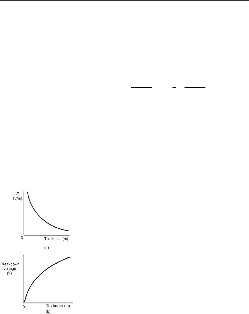
them, generally at a particular maximum temperature. Figure 39.1 shows
the typical shapes of graphs expected for electric field strength E plotted
against thickness and for breakdown voltage plotted against thickness. The
shape of the curves depend on a number of factors, and these include:
(i) the type of dielectric material,
(ii) the shape and size of the conductors associated with it,
(iii) the atmospheric pressure,
(iv) the humidity/moisture content of the material,
(v) the operating temperature.
Dielectric strength is an important factor in the design of capacitors as
well as transformers and high voltage insulators, and in motors and gener-
ators. Dielectrics vary in their ability to withstand large fields. Some
typical values of dielectric strength, together with resistivity and rela-
tive permittivity are shown in Table 39.1. The ceramics have very high
relative permittivities and they tend to be ‘ferroelectric’, i.e., they do not
lose their polarities when the electric field is removed. When ferroelectric
effects are present, the charge on a capacitor is given by Q D CV C
(remanent polarization). These dielectrics often possess an appreciable
Figure 39.1

714 Electrical Circuit Theory and Technology
TABLE 39.1 Dielectric properties of some common materials
Relative Dielectric
Resistivity, permittivity, strength
Material (m) ε
r
(V/m)
Air 1.0 3 ð 10
6
Paper 10
10
3.7 1.6 ð 10
7
Mica 5 ð 10
11
5.4 10
8
–10
9
Titaniumdioxide 10
12
100 6 ð 10
6
Polythene >10
11
2.3 4 ð 10
7
Polystyrene >10
13
2.5 2.5 ð 10
7
Ceramic (type 1) 4 ð 10
11
6–500 4.5 ð 10
7
Ceramic (type 2) 10
6
–10
13
500–1000 2 ð 10
6
–10
7
negative temperature coefficient of resistance. Despite this, a high permit-
tivity is often very desirable and ceramic dielectrics are widely used.
39.4 Thermal effects
As the temperature of most dielectrics is increased, the insulation
resistance falls rapidly. This causes the leakage current to increase, which
generates further heat. Eventually a condition known as thermal avalanche
or thermal runaway may develop, when the heat is generated faster than
it can be dissipated to the surrounding environment. The dielectric will
burn and thus fail.
Thermal effects may often seriously influence the choice and
application of insulating materials. Some important factors to be
considered include:
(i) the melting-point (for example, for waxes used in paper
capacitors),
(ii) aging due to heat,
(iii) the maximum temperature that a material will withstand without
serious deterioration of essential properties,
(iv) flash-point or ignitability,
(v) resistance to electric arcs,
(vi) the specific heat capacity of the material,
(vii) thermal resistivity,
(viii) the coefficient of expansion,
(ix) the freezing-point of the material.
39.5 Mechanical
properties
Mechanical properties determine, to varying degrees, the suitability of a
solid material for use as an insulator: tensile strength, transverse strength,
shearing strength and compressive strength are often specified. Most
solid insulations have a degree of inelasticity and many are quite brittle,
thus it is often necessary to consider features such as compressibility,

Dielectrics and dielectric loss 715
deformation under bending stresses, impact strength and extensibility,
tearing strength, machinability and the ability to fold without damage.
39.6 Types of practical
capacitor
Practical types of capacitor are characterized by the material used
for their dielectric. The main types include: variable air, mica, paper,
ceramic, plastic, titanium oxide and electrolytic. Refer back to Chapter 6,
Section 11, page 69, for a description of each type.
39.7 Liquid dielectrics
and gas insulation
Liquid dielectrics used for insulation purposes are refined mineral oils,
silicone fluids and synthetic oils such as chlorinated diphenyl. The prin-
cipal uses of liquid dielectrics are as a filling and cooling medium for
transformers, capacitors and rheostats, as an insulating and arc-quenching
medium in switchgear such as circuit breakers, and as an impregnant of
absorbent insulations— for example, wood, slate, paper and pressboard,
used mainly in transformers, switchgear, capacitors and cables.
Two gases used as insulation are nitrogen and sulphur hexafluoride.
Nitrogen is used as an insulation medium in some sealed transformers
and in power cables, and sulphur hexafluoride is finding increasing use
in switchgear both as an insulant and as an arc-extinguishing medium.
39.8 Dielectric loss and
loss angle
In capacitors with solid dielectrics, losses can be attributed to two causes:
(i) dielectric hysteresis, a phenomenon by which energy is expended
and heat produced as the result of the reversal of electrostatic stress
in a dielectric subjected to alternating electric stress—this loss is
analogous to hysteresis loss in magnetic materials;
(ii) leakage currents that may flow through the dielectric and along
surface paths between the terminals.
The total dielectric loss may be represented as the loss in an additional
resistance connected between the plates. This may be represented as either
a small resistance in series with an ideal capacitor or as a large resistance
in parallel with an ideal capacitor.
Series representation
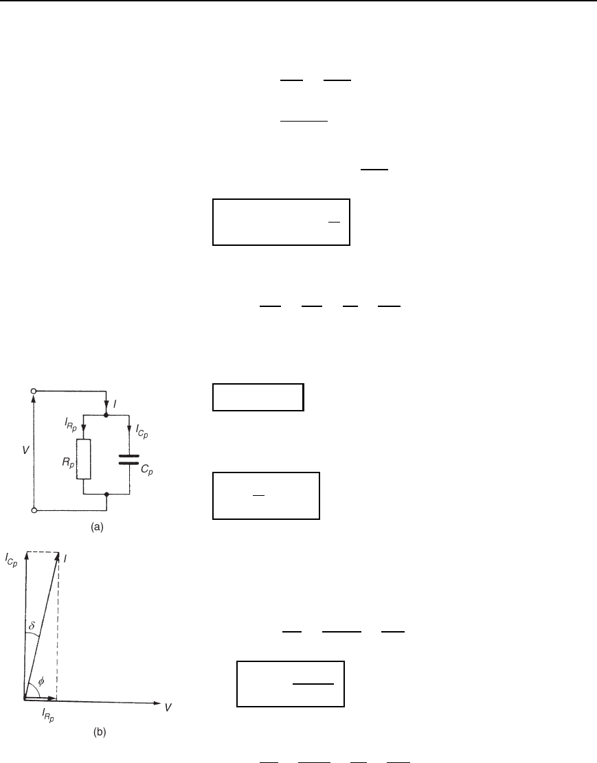
The circuit and phasor diagrams for the series representation are shown
in Figure 39.2. The circuit phase angle is shown as angle . If resistance
R
S
is zero then current I would lead voltage V by 90
°
, this being the case
of a perfect capacitor. The difference between 90
°
and the circuit phase
angle is the angle shown as υ. This is known as the loss angle of the
capacitor, i.e.,
loss angle, d = .90
°
− f/
Figure 39.2 (a) Circuit
diagram (b) Phasor diagram
716 Electrical Circuit Theory and Technology
For the equivalent series circuit,
tanυ D
V
R
S
V
C
S
D
IR
S
IX
C
S
i.e., tan υ D
R
S
1/ωC
S
D R
S
ωC
S
Since from Chapter 28, Q D
1
ωCR
then
tand = R
S
!C
S
=
1
Q
39.1
Power factor of capacitor,
cos D
V
R
S
V
D
IR
S
IZ
S
D
R
S
Z
S
³
R
S
X
C
S
since X
C
S
³ Z
S
when υ is small. Hence power factor D cosf ≈ R
S
!C
S
,
i.e.,
cosf ≈ tand
39.2
Dissipation factor, D is defined as the reciprocal of Q-factor and is an
indication of the quality of the dielectric, i.e.,
D =
1
Q
= tand
39.3
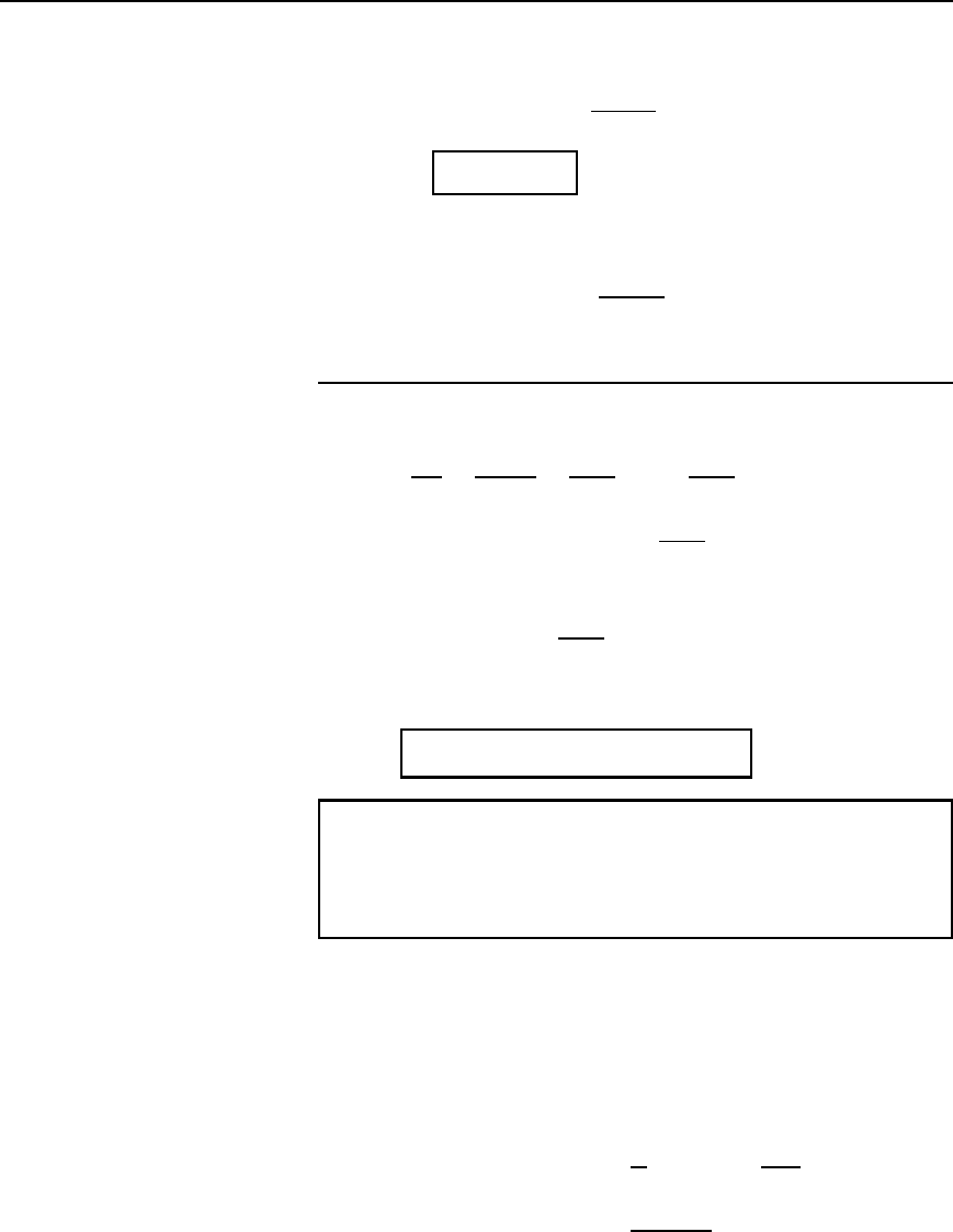
Parallel representation
The circuit and phasor diagrams for the parallel representation are shown
in Figure 39.3. From the phasor diagram,
tanυ D
I
R
P
I
C
P
D
V/R
P
V/X
C
P
D
X
C
P
R
P
i.e.,
tand =
1
R
P
!C
P
39.4
Power factor of capacitor,
cos D
I
R
P
I
D
V/R
P
V/Z
P
D
Z
P
R
P
³
X
C
P
R
P
Figure 39.3 (a) Circuit
diagram (b) Phasor diagram
Dielectrics and dielectric loss 717
since X
C
P
³ Z
P
, when υ is small. Hence
power factor D cos ³
1
R
P
ωC
P
i.e.,
cosf ≈ tand
(For equivalence between the series and the parallel circuit repre-
sentations,
C
S
³ C
P
D C and R
S
ωC
S
³
1
R
P
ωC
P
from which R
S
³ 1/R
P
ω
2
C
2
)
Power loss in the dielectric D VI cos. From the phasor diagram of
Figure 39.3
cosυ D
I
C
P
I
D
V/X
C
P
I
D
VωC
I
or I D
VωC
cosυ
Hence power loss D VI cos D V
VωC
cosυ
cos
However, cos D sinυ (complementary angles), thus
power loss D V
VωC
cosυ
sinυ D V
2
ωC tanυ
(since sin υ/ cosυ D tanυ)
Hence
dielectric power loss = V
2
!C tand
39.5
Problem 1. The equivalent series circuit for a particular capacitor
consists of a 1.5 resistance in series with a 400 pF capacitor.
Determine for the capacitor, at a frequency of 8 MHz, (a) the loss
angle, (b) the power factor, (c) the Q-factor, and (d) the dissipation
factor.
(a) From equation (39.1), for a series equivalent circuit,
tanυ D R
S
ωC
S
D 1.52 ð8 ð 10
6
400 ð 10
12
D 0.030159
Hence loss angle, d D arctan0.030159 D 1.727
°
or 0.030 rad.
(b) From equation (39.2), power factor D cos ³ tanυ D 0.030
(c) From equation 39.1, tan υ D
1
Q
hence Q D
1
tanυ
D
1
0.030159
D 33.16
