Bird J. Electrical Circuit Theory and Technology
Подождите немного. Документ загружается.


728 Electrical Circuit Theory and Technology
It follows that
E
min
=
V
b ln.b=a/
40.9
0
Problem 5. A concentric cable has a core diameter of 32 mm and
an inner sheath diameter of 80 mm. The core potential is 40 kV and
the relative permittivity of the dielectric is 3.5. Determine (a) the
capacitance per kilometre length of the cable, (b) the dielectric
stress at a radius of 30 mm, and (c) the maximum and minimum
values of dielectric stress.
(a) From equation (40.7), capacitance per metre length,
C D
2ε
0
ε
r
lnb/a
D
28.85 ð 10
12
3.5
ln40/16
D 212.4 ð 10
12
F/m
D 212.4 ð 10
12
ð 10
3
F/km
D 212 nF=km or 0.212 mF=km
(b) From equation (40.8), dielectric stress at radius r,
E D
V
r lnb/a
D
40 ð 10
3
30 ð 10
3
ln40/16
D 1.46
× 10
6
V=m or 1.46 MV=m
(c) From equation (40.9), maximum dielectric stress,
E
max
D
V
a lnb/a
D
40 ð 10
3
16 ð 10
3
ln40/16
D 2.73 MV=m
From equation (40.9
0
), minimum dielectric stress,
E
min
D
V
b lnb/a
D
40 ð 10
3
40 ð 10
3
ln40/16
D 1.09 MV=m
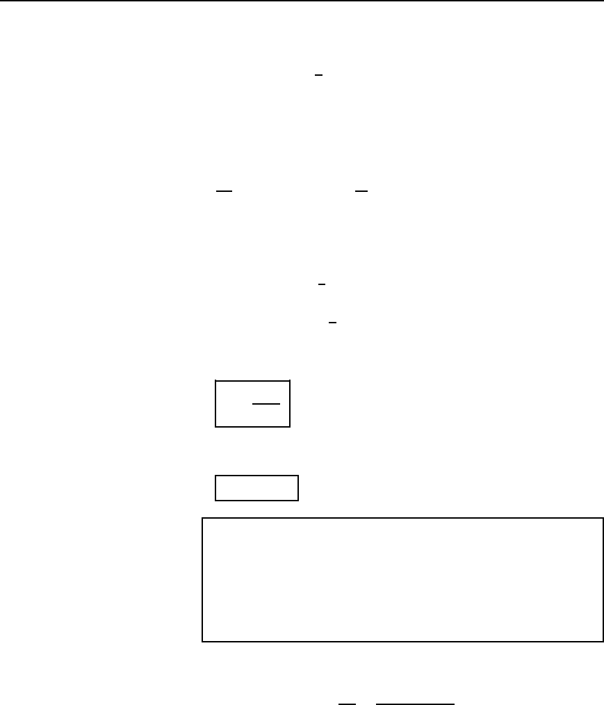
Dimensions of most economical cable
It is important to obtain the most economical dimensions when designing
a cable. A relationship between a and b may be obtained as follows. If
E
max
and V are both fixed values, then, from equation (40.9),
V
E
max
D a ln
b
a
Field theory 729
Letting V/E
max
D k, a constant, gives
a ln
b
a
D k
from which lnb/a D k/a, b/a D e
k/a
and b D ae
k/a
40.10
For the most economical cable, b will be a minimum value. Using the
product rule of calculus,
db
da
D e
k/a
1 C a
k
a
2
e
k/a
D 0 for a minimum value.
(Note, to differentiate e
k/a
with respect to a, an algebraic substitution may
be used, letting u D 1/a).
e
k/a
k
a
e
k/a
D 0
Therefore e
k/a
1
k
a
D 0
from which a D k. Thus
a =
V
E
max
40.11
From equation (40.10), internal sheath radius, b D ae
k/a
D ae
1
D ae, i.e.,
b = 2.718a
40.12
Problem 6. A single-core concentric cable is to be manufactured
for a 60 kV, 50 Hz transmission system. The dielectric used is
paper which has a maximum permissible safe dielectric stress of
10 MV/m rms and a relative permittivity of 3.5. Calculate (a) the
core and inner sheath radii for the most economical cable, (b) the
capacitance per metre length, and (c) the charging current per kilo-
metre run.
(a) From equation (40.11),
core radius, a D
V
E
m
D
60 ð 10
3
V
10 ð 10
6
V/m
D 6 ð 10
3
m D 6.0mm
From equation (40.12), internal sheath radius,
b D ae D 6.0e D 16.3mm

730 Electrical Circuit Theory and Technology
(b) From equation (40.7),
capacitance C D
2ε
0
ε
r
lnb/a
F/m
Since b D ae,
C D
2ε
0
ε
r
lne
D 2ε
0
ε
r
D 28.85 ð 10
12
3.5
D 195
× 10
−12
F=m or 195 pF=m
(c) Charging current D
V
X
C
D
V
1/ωC
D ωCV
D 250195 ð 10
12
60 ð 10
3
D 3.68 ð 10
3
A/m
Hence the charging current per kilometre D 3.68 A
Problem 7. A concentric cable has a core diameter of 25 mm and
an inside sheath diameter of 80 mm. The relative permittivity of the
dielectric is 2.5, the loss angle is 3.5 ð 10
3
rad and the working
voltage is 132 kV at 50 Hz frequency. Determine for a 1 km length
of the cable (a) the capacitance, (b) the charging current and (c) the
power loss.
(a) From equation (40.7),
capacitance, C D
2ε
0
ε
r
lnb/a
F/m
D
28.85 ð 10
12
2.5
ln40/12.5
ð 10
3
F/km
D 0.120
µF/km
Thus the capacitance fo
ra1kmlength of the cable is
0.120 mF
(b) Charging current I D
V
X
C
D
V
1/ωC
D ωCV
D 2500.120 ð 10
6
132 ð 10
3
D 4.98 A=km
(c) From equation (39.5), Chapter 39,
power loss D V
2
ωC tanυ
D 132 ð 10
3
2
2500.120 ð 10
6
tan3.5 ð 10
3
D 2300 W
Field theory 731
θ rad
Line of
force
r
4
r
3
r
2
r
1
Equipotential
lines
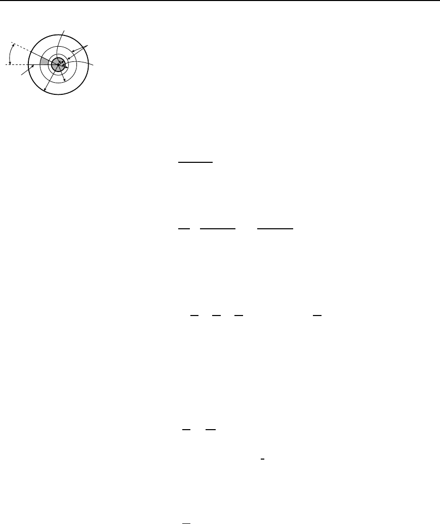
Figure 40.12
Concentric cable field plotting
Figure 40.12 shows a cross-section of a concentric cable having a core
radius r
1
and a sheath radius r
4
. It was shown in Section 40.1 that the
capacitance of a true square is given by C D ε
0
ε
r
farads/metre.
A curvilinear square is shown shaded in Figure 40.12. Such squares
can be made to have the same capacitance as a true square by the correct
choice of spacing between the lines of force and the equipotential surfaces
in the field plot.
From equation (40.7), the capacitance between cylindrical equipotential
lines at radii r
a
and r
b
is given by
C D
2ε
0
ε
r
lnr
b
/r
a
farads/metre
Thus for a sector of ! radians (see Figure 40.12) the capacitance is
given by
C D
!
2
2ε
0
ε
r
lnr
b
/r
a
D
!ε
0
ε
r
lnr
b
/r
a
farads/metre
Now if ! D lnr
b
/r
a
then C D ε
0
ε
r
F/m, the same as for a true square. If
! D lnr
b
/r
a
, then e
!
D r
b
/r
a
. Thus if, say, two equipotential surfaces
are chosen within the dielectric as shown in Figure 40.12, then e
!
D r
2
/r
1
,
e
!
D r
3
/r
2
and e
!
D r
4
/r
3
. Hence
e
!
3
D
r
2
r
1
ð
r
3
r
2
ð
r
4
r
3
, i.e., e
3q
=
r
4
r
1
40.13
It follows that e
2!
D r
3
/r
1
.
Equation (40.13) is used to determine the value of ! and hence the
number of sectors. Thus, for a concentric cable having a core radius 8 mm
and inner sheath radius 32 mm, if two equipotential surfaces within the
dielectric are chosen (and therefore form three capacitors in series in each
sector).
e
3!
D
r
4
r
1
D
32
8
D 4
Hence 3! D ln4 and ! D
1
3
ln4 D 0.462 rad (or 26.47
°
). Thus there
will be 2/0.462 D 13.6 sectors in the field plot. (Alternatively,
360
°
/26.47
°
D 13.6 sectors.) From above,
e
2!
D r
3
/r
1
, i.e., r
3
D r
1
e
2!
D 8e
20.462
D 20.15 mm
e
!
D
r
2
r
1
from which
r
2
D r
1
e
!
D 8e
0.462
D 12.70 mm
732 Electrical Circuit Theory and Technology
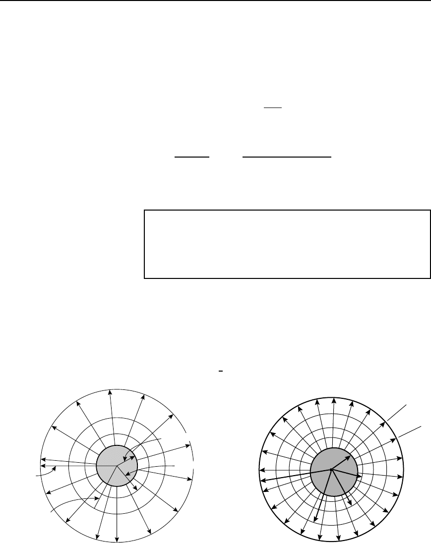
The field plot is shown in Figure 40.13. The number of parallel squares
measured along each equipotential is 13.6 and the number of series
squares measured along each line of force is 3. Hence in equation (40.4),
where C D ε
0
ε
r
xm/n, m D 13.6andn D 3.
If the dielectric has a relative permittivity of, say, 2.5, then the capacitance
per metre length,
C D 8.85 ð 10
12
2.51
13.6
3
D 100 pF
(From equation (40.7),
C D
2ε
0
ε
r
lnr
4
/r
1
F/m D
28.85 ð 10
12
2.5
ln32/8
D 100 F=m
Thus field plotting using curvilinear squares provides an alternative
method of determining the capacitance between concentric cylinders.
Problem 8. A concentric cable has a core diameter of 20 mm and
a sheath inside diameter of 60 mm. The permittivity of the dielec-
tric is 3.2. Using three equipotential surfaces within the dielectric,
determine the capacitance of the cable per metre length by the
method of curvilinear squares. Draw the field plot for the cable.
The field plot consists of radial lines of force dividing the cable cross-
section into a number of sectors, the lines of force cutting the equipotential
surfaces at right angles. Since three equipotential surfaces are required in
the dielectric, four capacitors in series are found in each sector of !
radians.
In Figure 40.14, r
1
D 20/2 D 10 mm and r
5
D 60/2 D 30 mm. It
follows from equation (40.13) that e
4!
D r
5
/r
1
D 30/10 D 3, from which
4! D ln3 and ! D
1
4
ln3 D 0.2747 rad.
r
1
= 8 mm
r
2
= 12.70 mm
r
3
= 20.15 mm
r
4
= 32 mm
Figure 40.13
0.2747 rad
r
1
r
2
r
3
r
4
r
5
Figure 40.14

Field theory 733
Thus the number of sectors in the plot shown in Figure 40.14 is
2/0.2747 D 22.9.
The three equipotential lines are shown in Figure 40.14 at radii of r
2
,
r
3
and r
4
.
From equation (40.13),
e
3!
D
r
4
r
1
, from which r
4
D r
1
e
3!
D 10e
30.2747
D 22.80 mm
e
2!
D
r
3
r
1
, from which r
3
D r
1
e
2!
D 10e
20.2747
D 17.32 mm
e
!
D
r
2
r
1
, from which r
2
D r
1
e
!
D 10e
0.2747
D 13.16 mm
Thus the field plot for the cable is as shown in Figure 40.14.
From equation (40.4), capacitance C D ε
0
ε
r
xm/n. The number of
parallel squares along each equipotential, m D 22.9 and the number of
series squares measured along each line of force, n D 4. Thus
capacitance C D 8.85 ð10
12
3.21
22.9
4
D 162 pF
(Checking, from equation (40.7),
capacitance C D
2ε
0
ε
r
lnr
5
/r
1
D
28.85 ð 10
12
3.2
ln30/10
D 162 pF
Further problems on the capacitance between concentric cylinders may be
found in Section 40.9, problems 4 to 10, page 753.
40.3 Capacitance of an
isolated twin line
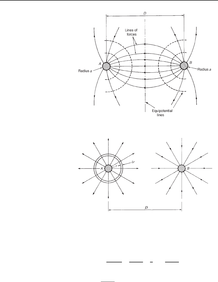
The field distribution with two oppositely charged, long conductors, A and
B, each of radius a is shown in Figure 40.15. The distance D between
the centres of the two conductors is such that D is much greater than a.
Figure 40.16 shows the field of each conductor separately.
Initially, let conductor A carry a charge of CQ coulombs per metre
while conductor B is uncharged. Consider a cylindrical element of radius r
about conductor A having a depth of 1 m and a thickness υr as shown in
Figure 40.16.
The electric flux density D at the element (i.e. at radius r) is given by
D D
charge
area
D
Q
2 ð 1
coulomb/metre
2
The electric field strength at the element,
E D
D
ε
0
ε
r
D
Q/2r
ε
0
ε
r
D
Q
2rε
0
ε
r
volts/metre
Since E D V/d, potential difference, V D Ed. Thus
p.d. at the element D Eυr D
Qυr
2rε
0
ε
r
volts
734 Electrical Circuit Theory and Technology
Figure 40.15
Figure 40.16
The potential may be considered as zero at a large distance from the
conductor. Let this be at radius R. Then the potential of conductor A
above zero, V
A
1
, is given by
V
A
1
D
R
a
Qdr
2rε
0
ε
r
D
Q
2ε
0
ε
r
R
a
1
r
dr D
Q
2ε
0
ε
r
[lnr]
R
a
D
Q
2ε
0
ε
r
[lnR lna]

Field theory 735
i.e., V
A
1
D
Q
2ε
0
ε
r
ln
R
a
Since conductor B lies in the field of conductor A, by reasoning similar
to that above, the potential at conductor B above zero, V
B
1
, is given by
V
B
1
D
R
D
Qdr
2rε
0
ε
r
D
Q
2ε
0
ε
r
[lnr]
R
D
D
Q
2ε
0
ε
r
ln
R
D
Repeating the above procedure, this time assuming that conductor B
carries a charge of Q coulombs per metre, while conductor A is
uncharged, gives
potential of conductor B below zero, V
B
2
D
Q
2ε
0
ε
r
ln
R
a
and the potential of conductor A below zero, due to the charge on
conductor B,
V
A
2
D
Q
2ε
0
ε
r
ln
R
D
When both conductors carry equal and opposite charges, the total potential
of A above zero is given by
V
A
1
C V
A
2
D
Q
2ε
0
ε
r
ln
R
a
C
Q
2ε
0
ε
r
ln
R
D
D
Q
2ε
0
ε
r
ln
R
a
ln
R
D
D
Q
2ε
0
ε
r
ln
R/a
R/D
D
Q
2ε
0
ε
r
ln
D
a
and the total potential of B below zero is given by
V
B
1
C V
B
2
D
Q
2ε
0
ε
r
ln
R
D
ln
R
a
D
Q
2ε
0
ε
r
ln
a
D
D
Q
2ε
0
ε
r
ln
D
a
Hence the p.d. between A and B is
2
Q
2ε
0
ε
r
ln
D
a
volts/metre
The capacitance between A and B per metre length,
C D
charge per metre
p.d.
D
Q
2Q/2ε
0
ε
r
lnD/a

736 Electrical Circuit Theory and Technology
i.e., C=
1
2
2p"
0
"
r
ln.D=a/
farads=metre
or
C D
p"
0
"
r
ln.D=a/
farads=metre
40.14
Problem 9. Two parallel wires, each of diameter 5 mm, are
uniformly spaced in air at a distance of 50 mm between centres.
Determine the capacitance of the line if the total length is 200 m.
From equation (40.14). capacitance per metre length,
C D
ε
0
ε
r
lnD/a
D
8.85 ð 10
12
1
ln50/5/2
since ε
r
D 1 for air,
D
8.85 ð 10
12
ln20
D 9.28 ð 10
12
F
Hence the capacitance of a 200 m length is 9.28 ð 10
12
ð 200 F
D 1860 pF or 1.86 nF
Problem 10. A single-phase circuit is composed of two parallel
conductors, each of radius 4 mm, spaced 1.2 m apart in air. The
p.d. between the conductors at a frequency of 50 Hz is 15 kV.
Determine, for a 1 km length of line, (a) the capacitance of the
conductors, (b) the value of charge carried by each conductor, and
(c) the charging current.
(a) From equation (40.14),
capacitance C D
ε
0
ε
r
lnD/a
D
8.85 ð 10
12
1
ln1.2/4 ð 10
3
D
8.85 ð 10
12
ln300
D 4.875 pF/m
Hence the capacitance per kilometre length is
4.875 ð 10
12
10
3
F D 4.875 nF
(b) Charge Q D CV D 4.875 ð10
9
15 ð 10
3
D 73.1 mC
(c) Charging current D
V
X
C
D
V
1/ωC
D ωCV
D 2504.875 ð 10
9
15 ð 10
3
D 0.023 A or 23 mA
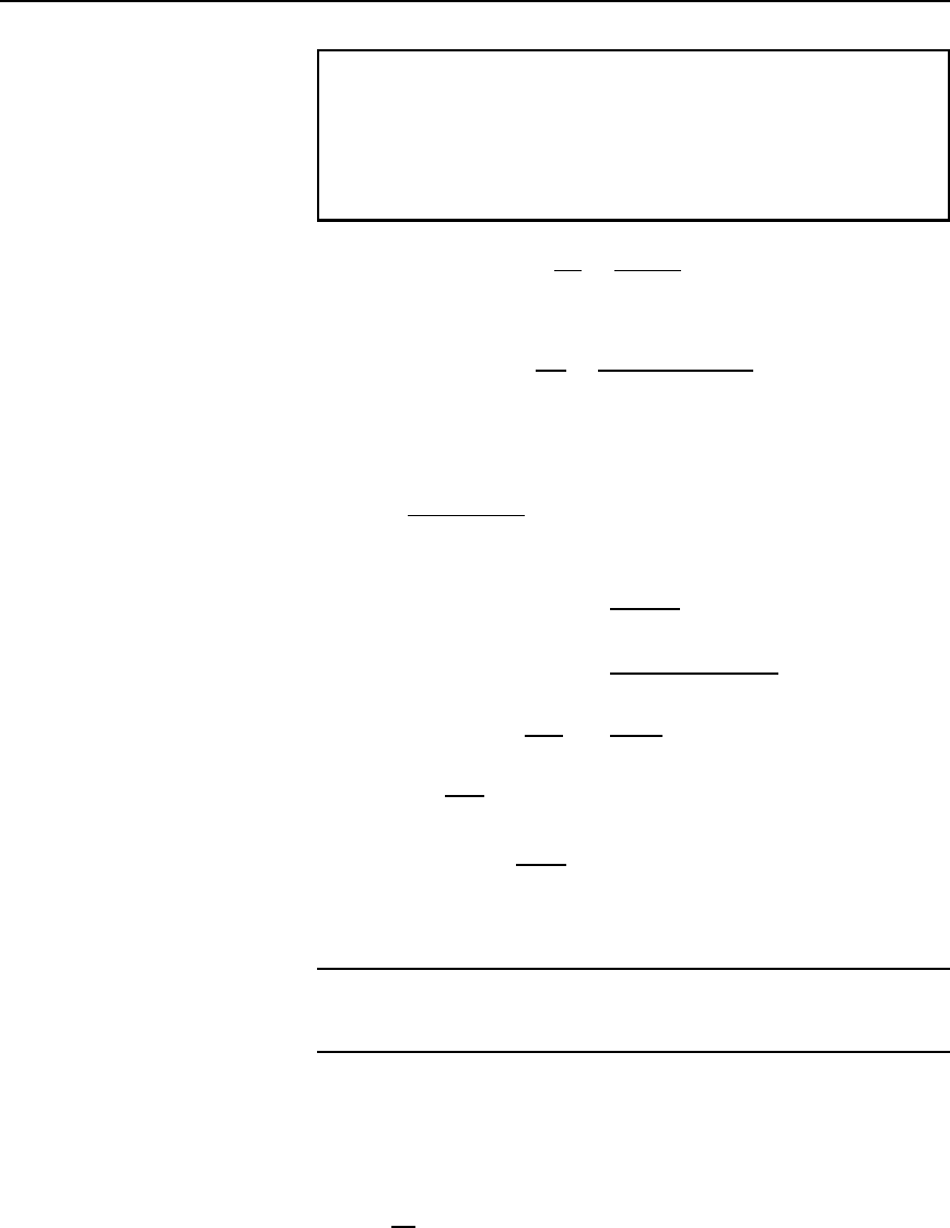
Field theory 737
Problem 11. The charging current for an 800 m run of isolated
twin line is not to exceed 15 mA. The voltage between the lines
is 10 kV at 50 Hz. If the line is air-insulated, determine (a) the
maximum value required for the capacitance per metre length,
and (b) the maximum diameter of each conductor if their distance
between centres is 1.25 m.
(a) Charging current I D
V
X
C
D
V
1/ωC
D ωCV
from which,
capacitance C D
I
ωV
D
15 ð 10
3
25010 ð 10
3
farads per
800 metre run
D 4.775 nF
Hence the required maximum value of capacitance
D
4.775 ð 10
9
800
F/m D 5.97 pF=m
(b) From equation (40.14)
C D
ε
0
ε
r
lnD/a
,
thus 5.97 ð10
12
D
8.85 ð 10
12
1
ln1.25/a
from which, ln
1.25
a
D
8.85
5.97
D 4.657
Hence
1.25
a
D e
4.657
D 105.3
and radius a D
1.25
105.3
m D 0.01187 m or 11.87 mm
Thus the maximum diameter of each conductor is 2 ð 11.87, i.e.,
23.7mm
Further problems on capacitance of an isolated twin line may be found in
Section 40.9, problems 11 to 15, page 754.
40.4 Energy stored in an
electric field
Consider the p.d. across a parallel-plate capacitor of capacitance C farads
being increased by d
v volts in dt seconds. If the corresponding increase
in charge is dq coulombs, then dq D Cd
v. If the charging current at that
instant is i amperes, then dq D idt. Thus idt D Cd
v, i.e.,
i D C
d
v
dt
