Bird J. Electrical Circuit Theory and Technology
Подождите немного. Документ загружается.


41 Attenuators
At the end of this chapter you should be able to:
ž understand the function of an attenuator
ž understand characteristic impedance and calculate for given
values
ž appreciate and calculate logarithmic ratios
ž design symmetrical T and symmetrical attenuators given
required attenuation and characteristic impedance
ž appreciate and calculate insertion loss
ž determine iterative and image impedances for asymmetrical T
and networks
ž appreciate and design the L-section attenuator
ž calculate attenuation for two-port networks in cascade
41.1 Introduction
An attenuator is a device for introducing a specified loss between a signal
source and a matched load without upsetting the impedance relationship
necessary for matching. The loss introduced is constant irrespective
of frequency; since reactive elements (L or C) vary with frequency, it
follows that ideal attenuators are networks containing pure resistances. A
fixed attenuator section is usually known as a ‘pad’.
Attenuation is a reduction in the magnitude of a voltage or current
due to its transmission over a line or through an attenuator. Any degree
of attenuation may be achieved with an attenuator by suitable choice of
resistance values but the input and output impedances of the pad must
be such that the impedance conditions existing in the circuit into which
it is connected are not disturbed. Thus an attenuator must provide the
correct input and output impedances as well as providing the required
attenuation.
Attenuation sections are made up of resistances connected as T or
arrangements (as introduced in Chapter 34).
Two-port networks
Networks in which electrical energy is fed in at one pair of terminals and
taken out at a second pair of terminals are called two-port networks.
Thus an attenuator is a two-port network, as are transmission lines,
transformers and electronic amplifiers. The network between the input
port and the output port is a transmission network for which a known
relationship exists between the input and output currents and voltages. If
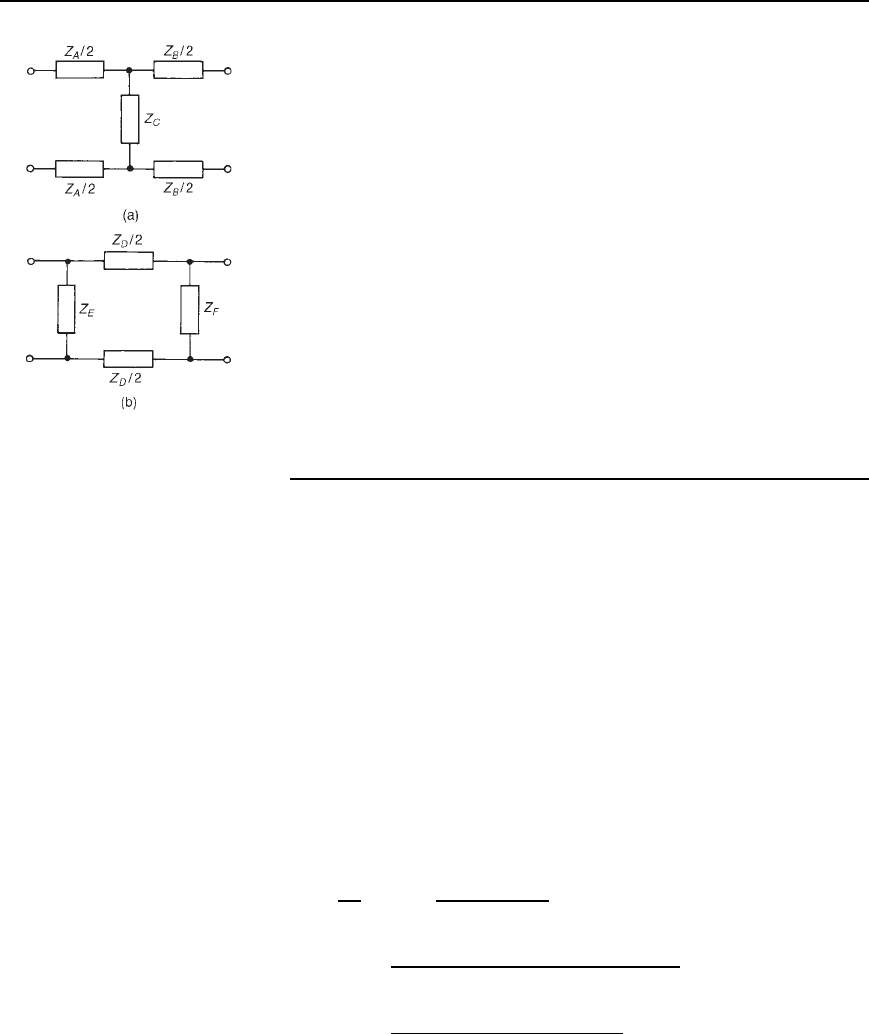
Figure 41.1 (a) T-network,
(b) -network
Attenuators 759
Figure 41.2 (a) Balanced
T-network, (b) Balanced
-network
a network contains only passive circuit elements, such as in an attenuator,
the network is said to be passive; if a network contains a source of e.m.f.,
such as in an electronic amplifier, the network is said to be active.
Figure 41.1(a) shows a T-network, which is termed symmetrical if
Z
A
D Z
B
and Figure 41.1(b) shows a -network which is symmetrical if
Z
E
D Z
F
.IfZ
A
6D Z
B
in Figure 41.1(a) and Z
E
6D Z
F
in Figure 41.1(b),
the sections are termed asymmetrical. Both networks shown have one
common terminal, which may be earthed, and are therefore said to
be unbalanced. The balanced form of the T-network is shown in
Figure 41.2(a) and the balanced form of the -network is shown in
Figure 41.2(b).
Symmetrical T- and -attenuators are discussed in Section 41.4 and
asymmetrical attenuators are discussed in Sections 41.6 and 41.7. Before
this it is important to understand the concept of characteristic impedance,
which is explained generally in Section 41.2 (characteristic impedances
will be used again in Chapter 44), and logarithmic units, discussed in
Section 41.3. Another important aspect of attenuators, that of insertion
loss, is discussed in Section 41.5. To obtain greater attenuation, sections
may be connected in cascade, and this is discussed in Section 41.8.
41.2 Characteristic
impedance
The input impedance of a network is the ratio of voltage to current (in
complex form) at the input terminals. With a two-port network the input
impedance often varies according to the load impedance across the output
terminals. For any passive two-port network it is found that a particular
value of load impedance can always be found which will produce an
input impedance having the same value as the load impedance. This is
called the iterative impedance for an asymmetrical network and its value
depends on which pair of terminals is taken to be the input and which
the output (there are thus two values of iterative impedance, one for each
direction). For a symmetrical network there is only one value for the
iterative impedance and this is called the characteristic impedance of
the symmetrical two-port network. Let the characteristic impedance be
denoted by Z
0
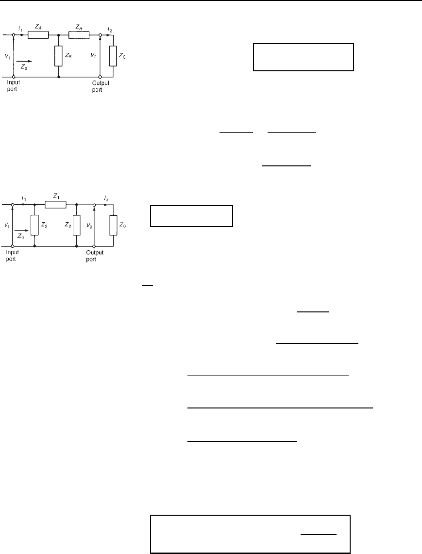
. Figure 41.3 shows a symmetrical T-network terminated
in an impedance Z
0
.
Let the impedance ‘looking-in’ at the input port also be Z
0
. Then
V
1
/I
1
D Z
0
D V
2
/I
2
in Figure 41.3. From circuit theory,
Z
0
D
V
1
I
1
D Z
A
C
Z
B
Z
A
C Z
0
Z
B
C Z
A
C Z
0
, since Z
A
C Z
0
is in parallel with Z
B
,
D
Z
2
A
C Z
A
Z
B
C Z
A
Z
0
C Z
A
Z
B
C Z
B
Z
0
Z
A
C Z
B
C Z
0
i.e. Z
0
D
Z
2
A
C 2Z
A
Z
B
C Z
A
Z
0
C Z
B
Z
0
Z
A
C Z
B
C Z
0
Thus Z
0
Z
A
C Z
B
C Z
0
D Z
2
A
C 2Z
A
Z
B
C Z
A
Z
0
C Z
B
Z
0
Z
0
Z
A
C Z
0
Z
B
C Z
2
0
D Z
2
A
C 2Z
A
Z
B
C Z
A
Z
0
C Z
B
Z
0
760 Electrical Circuit Theory and Technology
Figure 41.3
i.e., Z
2
0
D Z
2
A
C 2Z
A
Z
B
, from which
characteristic impedance,
Z
0
=
.Z
2
A
Y 2Z
A
Z
B
/
41.1
If the output terminals of Figure 41.3 are open-circuited, then the open-
circuit impedance, Z
OC
D Z
A
C Z
B
. If the output terminals of Figure 41.3
are short-circuited, then the short-circuit impedance,
Z
SC
D Z
A
C
Z
A
Z
B
Z
A
C Z
B
D
Z
2
A
C 2Z
A
Z
B
Z
A
C Z
B
Thus Z
OC
Z
SC
D Z
A
C Z
B
Z
2
A
C 2Z
A
Z
B
Z
A
C z
B
D Z
2
A
C 2Z
A
Z
B
Comparing this with equation (41.1) gives
Z
0
=
p
Z
OC
Z
SC
,
41.2
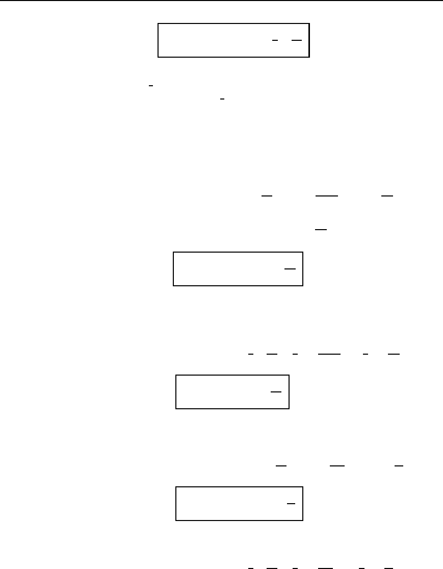
Figure 41.4 shows a symmetrical -network terminated in an
impedance Z
0
.
Figure 41.4
If the impedance ‘looking in’ at the input port is also Z
0
, then
V
1
I
1
D Z
0
D Z
2
in parallel with [Z
1
in series with Z
0
and Z
2
in parallel]
D Z
2
in parallel with
Z
1
C
Z
0
Z
2
Z
0
C Z
2
D Z
2
in parallel with
Z
1
Z
0
C Z
1
Z
2
C Z
0
Z
2
Z
0
C Z
2
i.e., Z
0
D
Z
2
Z
1
Z
0
C Z
1
Z
2
C Z
0
Z
2
/Z
0
C Z
2
Z
2
C Z
1
Z
0
C Z
1
Z
2
C Z
0
Z
2
/Z
0
C Z
2
D
Z
1
Z
2
Z
0
C Z
1
Z
2
2
C Z
0
Z
2
2
/Z
0
C Z
2
Z
2
Z
0
C Z
2
2
C Z
1
Z
0
C Z
1
Z
2
C Z
0
Z
2
/Z
0
C Z
2
i.e. Z
0
D
Z
1
Z
2
Z
0
C Z
1
Z
2
2
C Z
0
Z
2
2
Z
2
2
C 2Z
2
Z
0
C Z
1
Z
0
C Z
1
Z
2
Thus Z
0
Z
2
2
C 2Z
2
Z
0
C Z
1
Z
0
C Z
1
Z
2
D Z
1
Z
2
Z
0
C Z
1
Z
2
2
C Z
0
Z
2
2
2Z
2
Z
2
0
C Z
1
Z
2
0
D Z
1
Z
2
2
from which
characteristic impedance, Z
0
=
Z
1
Z
2
2
Z
1
Y 2Z
2
41.3

Attenuators 761
If the output terminals of Figure 41.4 are open-circuited, then the open-
circuit impedance,
Z
OC
D
Z
2
Z
1
C Z
2
Z
2
C Z
1
C Z
2
D
Z
2
Z
1
C Z
2
Z
1
C 2Z
2
If the output terminals of Figure 41.4 are short-circuited, then the short-
circuit impedance,
Z
SC
D
Z
2
Z
1
Z
1
C Z
2
Thus
Z
OC
Z
SC
D
Z
2
Z
1
C Z
2
Z
1
C 2Z
2
Z
2
Z
1
Z
1
C Z
2
D
Z
1
Z
2
2
Z
1
C 2Z
2
Comparing this expression with equation (41.3) gives
Z
0
=
p
.Z
OC
Z
SC
/,
41.2
0
which is the same as equation (41.2).
Thus the characteristic impedance Z
0
is given by Z
0
D
p
Z
OC
Z
SC
whether the network is a symmetrical T or a symmetrical .
Equations (41.1) to (41.3) are used later in this chapter.
41.3 Logarithmic ratios
The ratio of two powers P
1
and P
2
may be expressed in logarithmic form
as shown in Chapter 10.
Let P
1
be the input power to a system and P
2
the output power.
If logarithms to base 10 are used, then the ratio is said to be in bels,
i.e., power ratio in bels D lgP
2
/P
1
. The bel is a large unit and the
decibel (dB) is more often used, where 10 decibels D 1 bel, i.e.,
power ratio in decibels = 10lg
P
2
P
1
41.4
For example:
P
2
/P
1
Power ratio (dB)
110lg1D 0
100 10lg 100 DC20 (power gain)
1
10
10lg
1
10
D10 (power loss or attenuation)
If logarithms to base e (i.e., natural or Napierian logarithms) are used,
then the ratio of two powers is said to be in nepers (Np), i.e.,
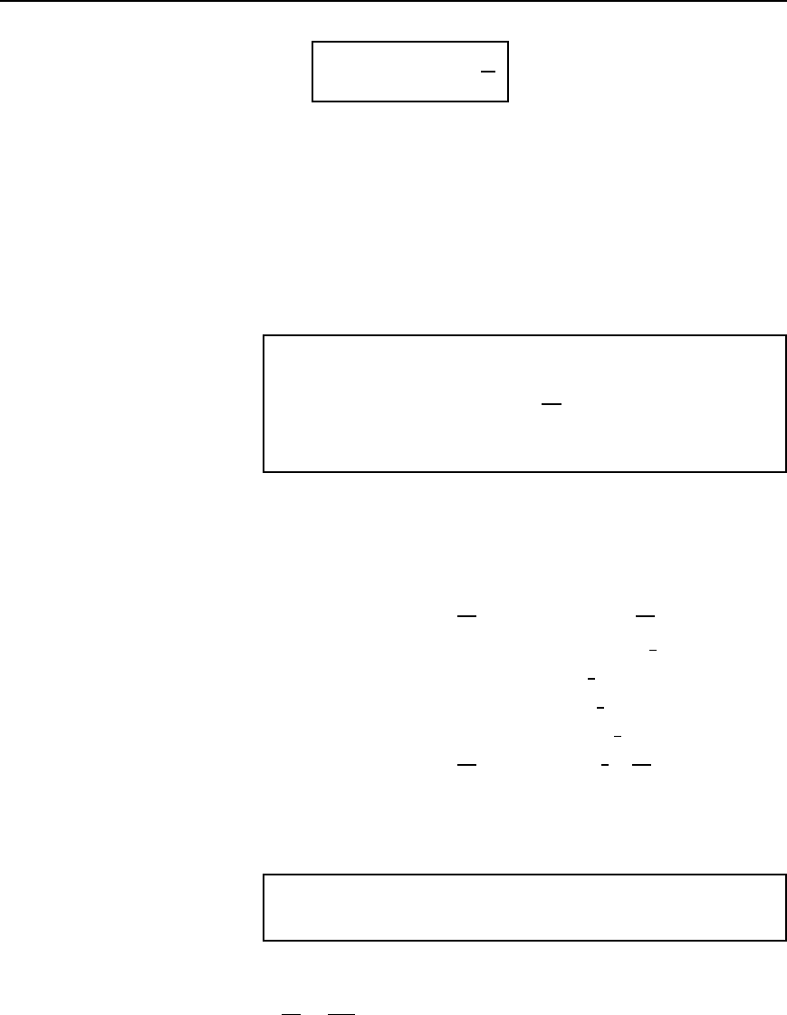
762 Electrical Circuit Theory and Technology
power ratio in nepers =
1
2
ln
P
2
P
1
41.5
Thus when the power ratio P
2
/P
1
D 5, the power ratio in nepers D
1
2
ln5 D 0.805 Np, and when the power ratio P
2
/P
1
D 0.1, the power
ratio in nepers D
1
2
ln0.1 D1.15 Np.
The attenuation of filter sections and along a transmission line are of an
exponential form and it is in such applications that the unit of the neper
is used (see Chapters 42 and 44).
If the powers P
1
and P
2
refer to power developed in two equal resistors,
R, then P
1
D V
2
1
/R and P
2
D V
2
2
/R. Thus the ratio (from equation (41.4))
can be expressed, by the laws of logarithms, as
ratio in decibels D 10lg
P
2
P
1
D 10lg
V
2
2
/R
V
2
1
/R
D 10lg
V
2
2
V
2
1
D 10lg
V
2
V
1
2
i.e. ratio in decibels = 20lg
V
2
V
1
41.6
Although this is really a power ratio, it is called the logarithmic voltage
ratio.
Alternatively, (from equation (41.5)),
ratio in nepers D
1
2
ln
P
2
P
1
D
1
2
ln
V
2
2
/R
V
2
1
/R
D
1
2
ln
V
2
V
1
2
i.e., ratio in nepers = ln
V
2
V
1
41.7
Similarly, if currents I
1
and I
2
in two equal resistors R give powers P
1
and P
2
then (from equation (41.4))
ratio in decibels D 10lg
P
2
P
1
D 10lg
I
2
2
R
I
2
1
R
D 10lg
I
2
I
1
2
i.e., ratio in decibels = 20lg
I
2
I
1
41.8
Alternatively (from equation (41.5)),
ratio in nepers D
1
2
ln
P
2
P
1
D
1
2
ln
I
2
2
R
I
2
1
R
2
D
1
2
ln
I
2
I
1
2
Attenuators 763
i.e., ratio in nepers = ln
I
2
I
1
41.9
In equations (41.4) to (41.9) the output-to-input ratio has been used.
However, the input-to-output ratio may also be used. For example,
in equation (41.6), the output-to-input voltage ratio is expressed as
20lgV
2
/V
1
dB. Alternatively, the input-to-output voltage ratio may be
expressed as 20 lgV
1
/V
2
dB, the only difference in the values obtained
being a difference in sign.
If 20lgV
2
/V
1
D 10 dB, say, then 20 lgV
1
/V
2
D10 dB. Thus if
an attenuator has a voltage input V
1
of 50 mV and a voltage output V
2
of 5 mV, the voltage ratio V
2
/V
1
is 5/50 or 1/10. Alternatively, this may
be expressed as ‘an attenuation of 10’, i.e., V
1
/V
2
D 10.
Problem 1. The ratio of output power to input power in a
system is
(a) 2 (b) 25 (c) 1000 and (d)
1
100
Determine the power ratio in each case (i) in decibels and (ii) in
nepers.
(i) From equation (41.4), power ratio in decibels D 10lgP
2
/P
1
.
(a) When P
2
/P
1
D 2, power ratio D 10lg2 D 3dB
(b) When P
2
/P
1
D 25, power ratio D 10lg25 D 14 dB
(c) When P
2
/P
1
D 1000, power ratio D 10lg1000 D 30 dB
(d) When P
2
/P
1
D
1
100
, power ratio D 10lg
1
100
D −20 dB
(ii) From equation (41.5), power ratio in nepers D
1
2
lnP
2
/P
1
.
(a) When P
2
/P
1
D 2, power ratio D
1
2
ln2 D 0.347 Np
(b) When P
2
/P
1
D 25, power ratio D
1
2
ln25 D 1.609 Np
(c) When P
2
/P
1
D 1000, power ratio D
1
2
ln1000 D 3.454 Np
(d) When P
2
/P
1
D
1
100
, power ratio D
1
2
ln
1
100
D −2.303 Np
The power ratios in (a), (b) and (c) represent power gains, since the
ratios are positive values; the power ratio in (d) represents a power loss
or attenuation, since the ratio is a negative value.
Problem 2. 5% of the power supplied to a cable appears at the
output terminals. Determine the attenuation in decibels.
If P
1
D input power and P
2
D output power, then
P
2
P
1
D
5
100
D 0.05

764 Electrical Circuit Theory and Technology
From equation (41.4), power ratio in decibels
D 10lgP
2
/P
1
D 10lg0.05 D13 dB.
Hence the attenuation (i.e., power loss) is 13 dB.
Problem 3. An amplifier has a gain of 15 dB. If the input power
is 12 mW, determine the output power.
From equation (41.4), decibel power ratio D 10lgP
2
/P
1
. Hence
15 D 10lgP
2
/12, where P
2
is the output power in milliwatts.
1.5 D lg
P
2
12
P
2
12
D 10
1.5
from the definition of a logarithm. Thus the output power,
P
2
D 1210
1.5
D 379.5mW
Problem 4. The current output of an attenuator is 50 mA. If the
current ratio of the attenuator is 1.32 Np, determine (a) the current
input and (b) the current ratio expressed in decibels. Assume that
the input and load resistances of the attenuator are equal.
(a) From equation (41.9), current ratio in nepers D lnI
2
/I
1
. Hence
1.32 D ln50/I
1
, where I
1
is the input current in mA.
e
1.32
D
50
I
1
from which, current input, I
1
D
50
e
1.32
D 50e
1.32
D 187.2 mA
(b) From equation (41.8),
current ratio in decibels D 20lg
I
2
I
1
D 20lg
50
187.2
D −11.47 dB
Further problems on logarithmic ratios may be found in Section 41.9,
problems 1 to 5, page 785.
41.4 Symmetrical T-and
p-attenuators
(a) Symmetrical T-attenuator
As mentioned in Section 41.1, the ideal attenuator is made up of pure
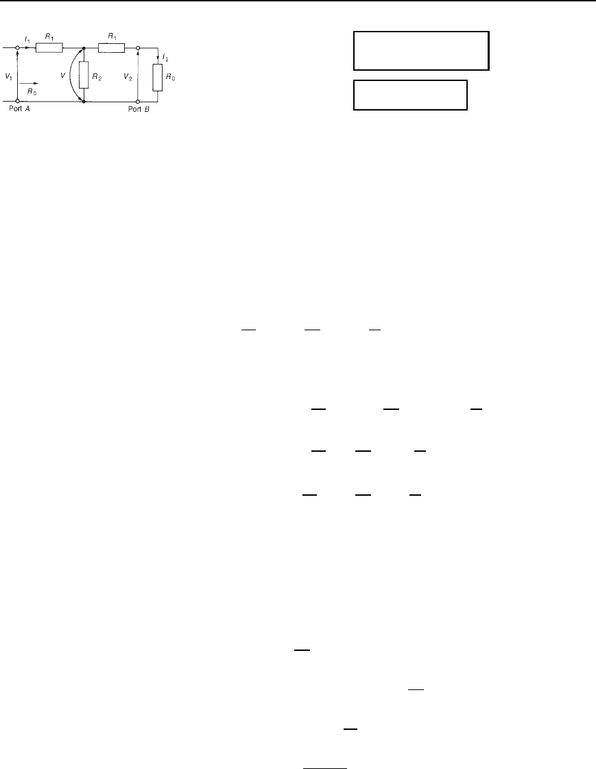
resistances. A symmetrical T-pad attenuator is shown in Figure 41.5 with
a termination R
0
connected as shown. From equation (41.1),
Attenuators 765
Figure 41.5 Symmetrical
T-pad attenuator
R
0
=
R
2
1
Y 2R
1
R
2
/
41.10
and from equation (41.2)
R
0
=
p
R
OC
R
SC
/
41.11
With resistance R
0
as the termination, the input resistance of the pad will
also be equal to R
0
. If the terminating resistance R
0
is transferred to port
A then the input resistance looking into port B will again be R
0
.
The pad is therefore symmetrical in impedance in both directions of
connection and may thus be inserted into a network whose impedance is
also R
0
. The value of R
0
is the characteristic impedance of the section.
As stated in Section 41.3, attenuation may be expressed as a voltage
ratio V
1
/V
2
(see Figure 41.5) or quoted in decibels as 20 lgV
1
/V
2
or,
alternatively, as a power ratio as 10 lgP
1
/P
2
. If a T-section is symmet-
rical, i.e., the terminals of the section are matched to equal impedances,
then
10lg
P
1
P
2
D 20lg
V
1
V
2
D 20lg
I
1
I
2
since R
IN
D R
LOAD
D R
0
, i.e.,
10lg
P
1
P
2
D 10lg
V
1
V
2
2
D 10lg
I
1
I
2
2
from which
P
1
P
2
D
V
1
V
2
2
D
I
1
I
2
2
or
P
1
P
2
D
V
1
V
2
D
I
1
I
2
Let N D V
1
/V
2
or I
1
/I
2
or
p
P
1
/P
2
, where N is the attenuation. In
Section 41.5, page 772, it is shown that, for a matched network, i.e., one
terminated in its characteristic impedance, N is in fact the insertion loss
ratio. (Note that in an asymmetrical network, only the expression N D
p
P
1
/P
2
may be used—see Section 41.7 on the L-section attenuator)
From Figure 41.5,
current I
1
D
V
1
R
0
Voltage V D V
1
I
1
R
1
D V
1
V
1
R
0
R
1
i.e., V D V
1
1
R
1
R
0
Voltage V
2
D
R
0
R
1
C R
0
V by voltage division

766 Electrical Circuit Theory and Technology
i.e., V
2
D
R
0
R
1
C R
0
V
1
1
R
1
R
0
D V
1
R
0
R
1
C R
0
R
0
R
1
R
0
Hence
V
2
V
1
D
R
0
R
1
R
0
C R
1
or
V
1
V
2
D N D
R
0
C R
1
R
0
R
1
41.12
From equation (41.12) and also equation (41.10), it is possible to derive
expressions for R
1
and R
2
in terms of N and R
0
, thus enabling an atten-
uator to be designed to give a specified attenuation and to be matched
symmetrically into the network. From equation (41.12),
NR
0
R
1
D R
0
C R
1
NR
0
NR
1
D R
0
C R
1
NR
0
R
0
D R
1
C NR
1
R
0
N 1 D R
1
1 C N
from which
R
1
= R
0
.N − 1/
.N Y 1/
41.13
From equation (41.10), R
0
D
R
2
1
C 2R
1
R
2
i.e., R
2
0
D R
2
1
C 2R
1
R
2
,
from which, R
2
D
R
2
0
R
2
1
2R
1
Substituting for R
1
from equation (41.13) gives
R
2
D
R
2
0
[R
0
N 1/N C 1]
2
2[R
0
N 1/N C1]
D
[R
2
0
N C 1
2
R
2
0
N 1
2
]/N C 1
2
2R
0
N 1/N C 1
i.e., R
2
D
R
2
0
[N C 1
2
N 1
2
]
2R
0
N 1N C 1
D
R
0
[N
2
C 2N C 1 N
2
2N C 1]
2N
2
1
D
R
0
4N
2N
2
1
Hence
R
2
= R
0
2N
N
2
− 1
41.14
Thus if the characteristic impedance R
0
and the attenuation ND V
1
/V
2
)
are known for a symmetrical T-network then values of R
1
and R
2
may be
Attenuators 767
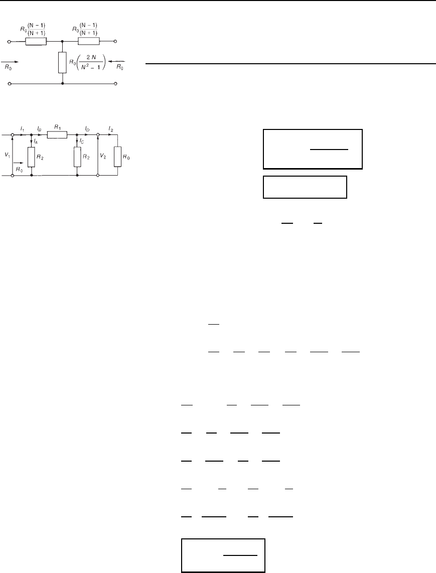
Figure 41.6
calculated. Figure 41.6 shows a T-pad attenuator having input and output
impedances of R
0
with resistances R
1
and R
2
expressed in terms of R
0
and N.
(b) Symmetrical p-attenuator
A symmetrical -attenuator is shown in Figure 41.7 terminated in R
0
.
From equation (41.3),
characteristic impedance
R
0
=
R
1
R
2
2
R
1
Y 2R
2
41.15
and from equation (41.2
0
),
R
0
=
p
R
OC
R
SC
/
41.16
Figure 41.7 Symmetrical
-attenuator
Given the attenuation factor N D
V
1
V
2
D
I
1
I
2
and the characteristic impedance R
0
, it is possible to derive expressions
for R
1
and R
2
, in a similar way to the T-pad attenuator, to enable a
-attenuator to be effectively designed.
Since N D V
1
/V
2
then V
2
D V
1
/N. From Figure 41.7,
current I
1
D I
A
C I
B
and current I
B
D I
C
C I
D
. Thus
current I
1
D
V
1
R
0
D I
A
C I
C
C I
D
D
V
1
R
2
C
V
2
R
2
C
V
2
R
0
D
V
1
R
2
C
V
1
NR
2
C
V
1
NR
0
since V
2
D V
1
/N, i.e.,
V
1
R
0
D V
1
1
R
2
C
1
NR
2
C
1
NR
0
Hence
1
R
0
D
1
R
2
C
1
NR
2
C
1
NR
0
1
R
0
1
NR
0
D
1
R
2
C
1
NR
2
1
R
0
1
1
N
D
1
R
2
1 C
1
N
1
R
0
N 1
N
D
1
R
2
N C 1
N
Thus R
2
= R
0
.N Y 1/
.N − 1/
41.17
