Bird J. Electrical Circuit Theory and Technology
Подождите немного. Документ загружается.

768 Electrical Circuit Theory and Technology
From Figure 41.7, current I
1
D I
A
C I
B
, and since the p.d. across R
1
is
V
1
V
2
,
V
1
R
0
D
V
1
R
2
C
V
1
V
2
R
1
V
1
R
0
D
V
1
R
2
C
V
1
R
1
V
2
R
1
V
1
R
0
D
V
1
R
2
C
V
1
R
1
V
1
NR
1
since V
2
D V
1
/N
1
R
0
D
1
R
2
C
1
R
1
1
NR
1
1
R
0
1
R
2
D
1
R
1
1
1
N
1
R
0
N 1
R
0
N C 1
D
1
R
1
N 1
N
from equation (41.17),
1
R
0
1
N 1
N C 1
D
1
R
1
N 1
N
1
R
0
N C 1 N 1
N C 1
D
1
R
1
N 1
N
1
R
0
2
N C 1
D
1
R
1
N 1
N
R
1
D R
0
N 1
N
N C 1
2
Hence R
1
= R
0
N
2
− 1
2N
41.18
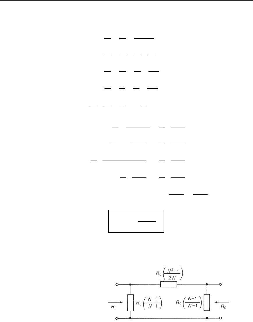
Figure 41.8 shows a -attenuator having input and output impedances of
R
0
with resistances R
1
and R
2
expressed in terms of R
0
and N.
Figure 41.8
Attenuators 769
Figure 41.9
There is no difference in the functions of the T- and -attenuator pads
and either may be used in a particular situation.
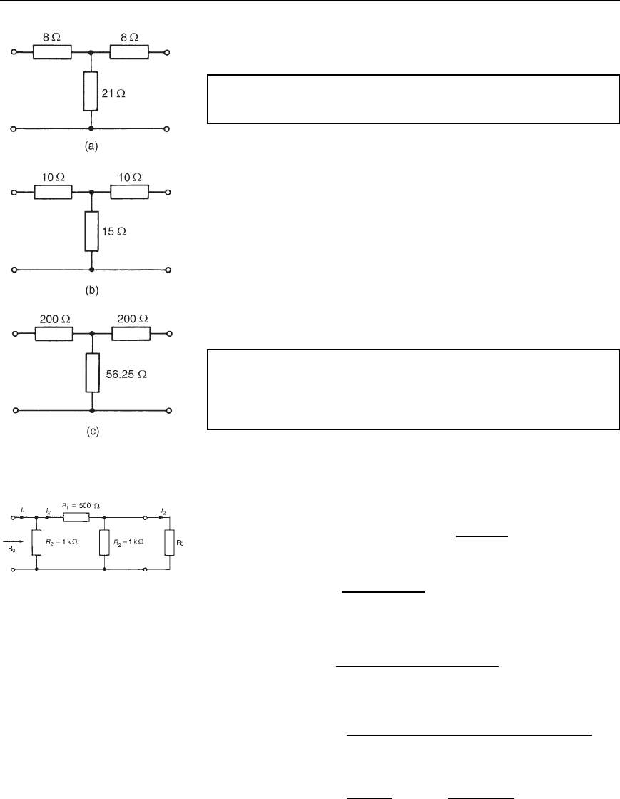
Problem 5. Determine the characteristic impedance of each of the
attenuator sections shown in Figure 41.9.
From equation (41.10), for a T-section attenuator the characteristic
impedance,
R
0
D
R
2
1
C 2R
1
R
2
.
(a) R
0
D
8
2
C 2821 D
p
400 D 20 Z
(b) R
0
D
10
2
C 21015 D
p
400 D 20 Z
(c) R
0
D
200
2
C 220056.25 D
p
62500 D 250 Z
It is seen that the characteristic impedance of parts (a) and (b) is the same.
In fact, there are numerous combinations of resistances R
1
and R
2
which
would give the same value for the characteristic impedance.
Problem 6. A symmetrical -attenuator pad has a series arm of
500 resistance and each shunt arm of 1 k resistance. Determine
(a) the characteristic impedance, and (b) the attenuation (in dB)
produced by the pad.
The -attenuator section is shown in Figure 41.10 terminated in its char-
acteristic impedance, R
0
.
(a) From equation (41.15), for a symmetrical -attenuator section,
characteristic impedance, R
0
D
R
1
R
2
2
R
1
C 2R
2
Hence R
0
D
5001000
2
500 C 21000
D 447
Figure 41.10
(b) Attenuation D 20lgI
1
/I
2
dB. From Figure 41.10,
current I
X
D
R
2
R
2
C R
1
C R
2
R
0
/R
2
C R
0
I
1
,
by current division
i.e., I
X
D
1000
1000 C 500 C 1000447/1000 C 447
I
1
D 0.553I
1
and current I
2
D
R
2
R
2
C R
0
I
X
D
1000
1000 C 447
I
X
D 0.691I
X
770 Electrical Circuit Theory and Technology
Hence I
2
D 0.6910.553I
1
D 0.382I
1
and I
1
/I
2
D 1/0.382
D 2.617. Thus
attenuation D 20lg2.617 D 8.36 dB
(Alternatively, since I
1
/I
2
D N, then the formula
R
2
D R
0
N C 1
N 1
may be transposed for N, from which attenuation = 20lgN.)
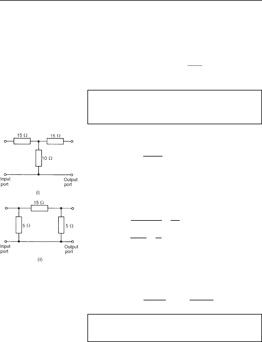
Problem 7. For each of the attenuator networks shown in
Figure 41.11, determine (a) the input resistance when the output
port is open-circuited, (b) the input resistance when the output port
is short-circuited, and (c) the characteristic impedance.
(i) For the T-network shown in Figure 41.11(i):
(a) R
OC
D 15 C 10 D 25 Z
(b) R
SC
D 15 C
10 ð 15
10 C15
D 15 C 6 D 21 Z
(c) From equation (41.11), R
0
D
p
R
OC
R
SC
D
p
[2521]
D 22.9 Z
(Alternatively, from equation (41.10),
R
0
D
R
2
1
C 2R
1
R
2
D
15
2
C 21510 D 22.9 Z
(ii) For the -network shown in Figure 41.11(ii):
(a) R
OC
D
5 ð 15 C 5
5 C15 C 5
D
100
25
D 4 Z
(b) R
SC
D
5 ð 15
5 C 15
D
75
20
D 3.75 Z
(c) From equation (41.16),
R
0
D
p
R
OC
R
SC
as for a T-network
D
p
[43.75] D
p
15 D 3.87 Z
(Alternatively, from equation (41.15),
R
0
D
R
1
R
2
2
R
1
C 2R
2
D
155
2
15 C 25
D 3.87 Z
Problem 8. Design a T-section symmetrical attenuator pad to
provide a voltage attenuation of 20 dB and having a characteristic
impedance of 600 .
Figure 41.11
Attenuators 771
Voltage attenuation in decibels D 20lgV
1
/V
2
.
Attenuation, N D V
1
/V
2
, hence 20 D 20lgN, from which N D 10.
Characteristic impedance, R
0
D 600
From equation (41.13),
resistance R
1
D
R
0
N 1
N C 1
D
60010 1
10 C 1
D 491 Z
From equation (41.14),
resistance R
2
D R
0
2N
N
2
1
D 600
210
10
2
1
D 121 Z
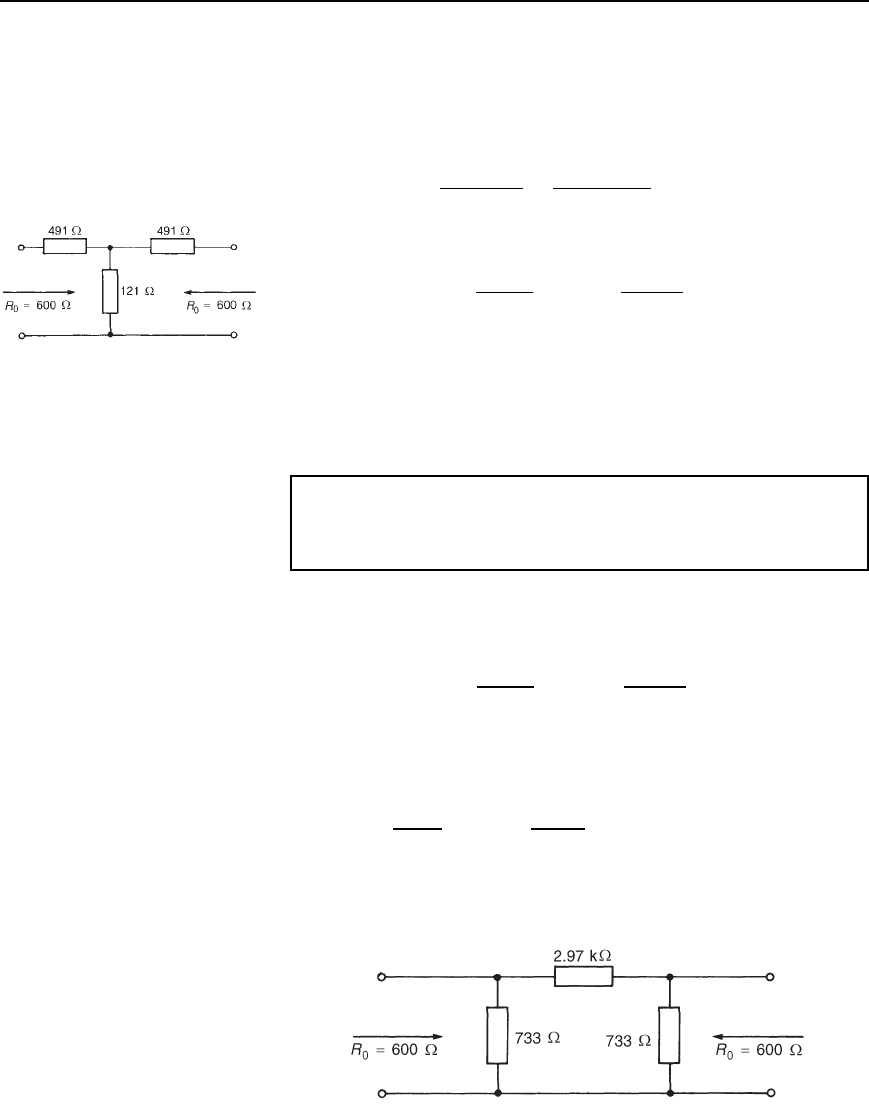
Thus the T-section attenuator shown in Figure 41.12 has a voltage atten-
uation of 20 dB and a characteristic impedance of 600 .
Figure 41.12
(Check: From equation (41.10)),
R
0
D
R
2
1
C 2R
1
R
2
D
[491
2
C 2491121] D 600
Problem 9. Design a -section symmetrical attenuator pad to
provide a voltage attenuation of 20 dB and having a characteristic
impedance of 600 .
From problem 8, N D 10 and R
0
D 600
From equation (41.18),
resistance R
1
D R
0
N
2
1
2N
D 600
10
2
1
210
D 2970 Z or 2.97 kZ
From equation (41.17),
R
2
D R
0
N C 1
N 1
D 600
10 C 1
10 1
D 733 Z
Thus the -section attenuator shown in Figure 41.13 has a voltage atten-
uation of 20 dB and a characteristic impedance of 600 .
Figure 41.13
772 Electrical Circuit Theory and Technology
(Check: From equation (41.15),
R
0
D
R
1
R
2
2
R
1
C 2R
2
D
2970733
2
2970 C 2733
D 600
Further problems on symmetrical T- and -attenuators may be found in
Section 41.9, problems 6 to 15, page 785.
41.5 Insertion loss
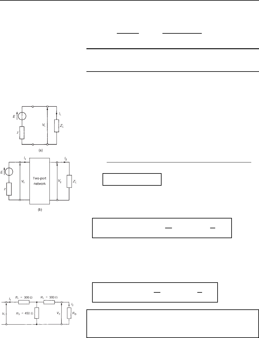
Figure 41.14(a) shows a generator E connected directly to a load Z
L
.Let
the current flowing be I
L
and the p.d. across the load V
L
. z is the internal
impedance of the source.
Figure 41.14(b) shows a two-port network connected between the
generator E and load Z
L
.
The current through the load, shown as I
2
, and the p.d. across the
load, shown as V
2
, will generally be less than current I
L
and voltage V
L
of Figure 41.14(a), as a result of the insertion of the two-port network
between generator and load.
The insertion loss ratio, A
L
,isdefinedas
A
L
D
voltage across load when connected directly to the generator
voltage across load when the two-port network is connected
i.e.,
A
L
= V
L
=V
2
= I
L
=I
2
41.19
Figure 41.14
since V
L
D I
L
Z
L
and V
2
D I
2
Z
L
. Since both V
L
and V
2
refer to p.d.’s
across the same impedance Z
L
, the insertion loss ratio may also be
expressed (from Section 41.3) as
insertion loss ratio= 20lg
V
L
V
2
dB or 20lg
I
L
I
2
dB
41.20
When the two-port network is terminated in its characteristic impedance
Z
0
the network is said to be matched. In such circumstances the input
impedance is also Z
0
, thus the insertion loss is simply the ratio of input
to output voltage (i.e., V
1
/V
2
. Thus, for a network terminated in its
characteristic impedance,
insertion loss = 20 lg
V
1
V
2
dB or 20 lg
I
1
I
2
dB 41.21
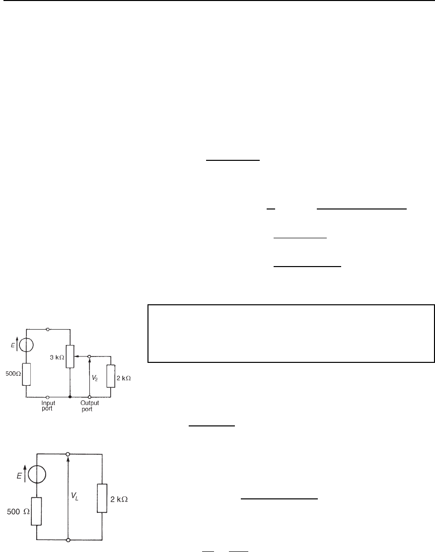
Problem 10. The attenuator shown in Figure 41.15 feeds a
matched load. Determine (a) the characteristic impedance R
0
,and
(b) the insertion loss in decibels.
Figure 41.15
Attenuators 773
(a) From equation (41.10), the characteristic impedance of a symmetric
T-pad attenuator is given by
R
0
D
R
2
1
C 2R
1
R
2
D
[300
2
C 2300450] D 600 Z.
(b) Since the T-network is terminated in its characteristic impedance,
then from equation (41.21),
insertion loss D 20lgV
1
/V
2
dB or 20lgI
1
/I
2
dB.
By current division in Figure 41.15,
I
2
D
R
2
R
2
C R
1
C R
0
I
1
Hence
insertion loss D 20lg
I
1
I
2
D 20lg
I
1
R
2
/R
2
C R
1
C R
0
I
1
D 20lg
R
2
C R
1
C R
0
R
2
D 20lg
450 C 300 C 600
450
D 20lg3 D 9.54 dB
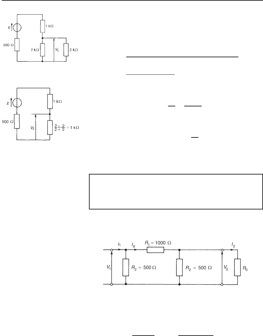
Problem 11. A 0–3 k rheostat is connected across the output of
a signal generator of internal resistance 500 .Ifaloadof2k
is connected across the rheostat, determine the insertion loss at a
tapping of (a) 2 k,(b)1k.
The circuit diagram is shown in Figure 41.16. Without the rheostat in
the circuit the voltage across the 2 k load, V
L
(see Figure 41.17), is
given by
V
L
D
2000
2000 C 500
E D 0.8E
(a) With the 2 k tapping, the network of Figure 41.16 may be redrawn
as shown in Figure 41.18, which in turn is simplified as shown in
Figure 41.19. From Figure 41.19,
voltage V
2
D
1000
1000 C 1000 C 500
E D 0.4E
Figure 41.16
Hence, from equation (41.19), insertion loss ratio,
A
L
D
V
L
V
2
D
0.8E
0.4E
D 2
Figure 41.17
774 Electrical Circuit Theory and Technology
Figure 41.18
or, from equation (41.20),
insertion loss D 20lgV
L
/V
2
D 20lg2 D 6.02 dB
(b) With the 1 k tapping, voltage V
2
is given by
V
2
D
1000 ð 2000/1000 C 2000
1000 ð2000/1000 C 2000 C 2000 C 500
E
D
666.7
666.7 C 2000 C 500
E D 0.211 E
Hence, from equation (41.19),
insertion loss ratio A
L
D
V
L
V
2
D
0.8E
0.211E
D 3.79
or, from equation (41.20),
insertion loss in decibels D 20lg
V
L
V
2
D 20lg3.79
D 11.57 dB
(Note that the insertion loss is not doubled by halving the tapping.)
Figure 41.19
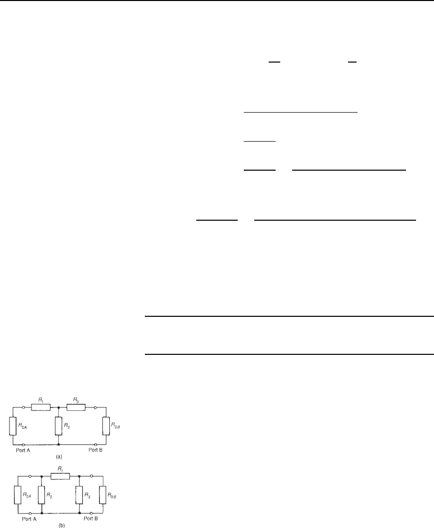
Problem 12. A symmetrical -attenuator pad has a series arm of
resistance 1000 and shunt arms each of 500 . Determine (a) its
characteristic impedance, and (b) the insertion loss (in decibels)
when feeding a matched load.
The -attenuator pad is shown in Figure 41.20, terminated in its charac-
teristic impedance, R
0
.
Figure 41.20
(a) From equation (41.15), the characteristic impedance of a symmet-
rical attenuator is given by
R
0
D
R
1
R
2
2
R
1
C 2R
2
D
1000500
2
1000 C 2500
D 354 Z
Attenuators 775
(b) Since the attenuator network is feeding a matched load, from equa-
tion (41.21),
insertion loss D 20lg
V
1
V
2
dB D 20 lg
I
1
I
2
dB
From Figure 41.20, by current division,
current I
X
D
R
2
R
2
C R
1
C R
2
R
0
/R
2
C R
0
I
1
and current I
2
D
R
2
R
2
C R
0
I
X
D
R
2
R
2
C R
0
R
2
R
2
C R
1
C R
2
R
0
/R
2
C R
0
I
1
i.e.,
I
2
D
500
500 C 354
500
500 C 1000 C 500354/500 C 354
I
1
D 0.58550.2929I
1
D 0.1715I
1
Hence I
1
/I
2
D 1/0.1715 D 5.83
Thus the insertion loss in decibels D 20lgI
1
/I
2
D 20lg5.83 D 15.3dB
Further problems on insertion loss may be found in Section 41.9, prob-
lems 16 to 18, page 786.
41.6 Asymmetrical T-
and p-sections
Figure 41.21(a) shows an asymmetrical T-pad section where resistance
R
1
6D R
3
. Figure 41.21(b) shows an asymmetrical -section where
R
2
6D R
3
.
When viewed from port A, in each of the sections, the output
impedance is R
OB
; when viewed from port B, the input impedance is
R
OA
. Since the sections are asymmetrical R
OA
does not have the same
value as R
OB
.
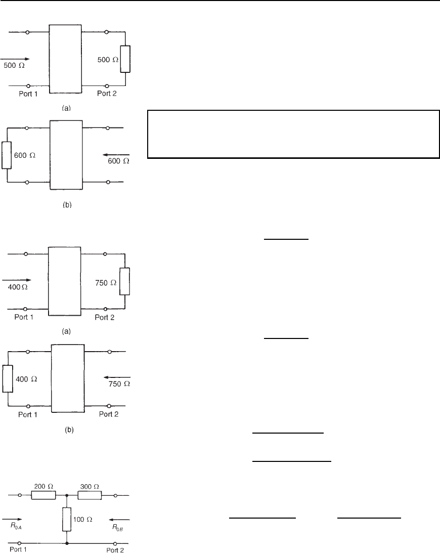
Iterative impedance is the term used for the impedance measured at
one port of a two-port network when the other port is terminated with
an impedance of the same value. For example, the impedance looking
into port 1 of Figure 41.22(a) is, say, 500 when port 2 is terminated
in 500 and the impedance looking into port 2 of Figure 41.22(b) is,
say, 600 when port 1 is terminated in 600 . (In symmetric T- and
-sections the two iterative impedances are equal, this value being the
characteristic impedance of the section.)
An image impedance is defined as the impedance which, when
connected to the terminals of a network, equals the impedance presented
to it at the opposite terminals. For example, the impedance looking into
Figure 41.21 (a) Asymmetrical
T-pad section, (b) Asymmetrical
-section
776 Electrical Circuit Theory and Technology
Figure 41.22
port 1 of Figure 41.23(a) is, say, 400 when port 2 is terminated in, say
750 , and the impedance seen looking into port 2 (Figure 41.23(b)) is
750 when port 1 is terminated in 400 . An asymmetrical network is
correctly terminated when it is terminated in its image impedance. (If the
image impedances are equal, the value is the characteristic impedance.)
The following worked problems show how the iterative and image
impedances are determined for asymmetrical T- and -sections.
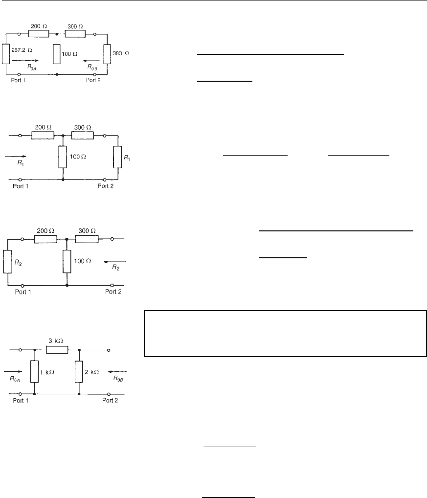
Problem 13. An asymmetrical T-section attenuator is shown in
Figure 41.24. Determine for the section (a) the image impedances,
and (b) the iterative impedances.
(a) The image impedance R
OA
seen at port 1 in Figure 41.24 is given by
equation (41.11): R
OA
D
p
R
OC
R
SC
, where R
OC
and R
SC
refer to
port 2 being respectively open-circuited and short-circuited.
R
OC
D 200 C 100 D 300
and R
SC
D 200 C
100300
100 C 300
D 275
Hence R
OA
D
p
[300275] D 287.2 Z
Figure 41.23
Similarly, R
OB
D
p
R
OC
R
SC
, where R
OC
and R
SC
refer to port 1
being respectively open-circuited and short-circuited.
R
OC
D 300 C 100 D 400
and R
SC
D 300 C
200100
200 C 100
D 366.7
Hence R
OB
D
p
[400366.7] D 383 Z.
Thus the image impedances are 287.2 Z and 383 Z and are
shown in the circuit of Figure 41.25.
(Checking:
R
OA
D 200 C
100300 C 383
100 C 300 C 383
D 287.2
and R
OB
D 300 C
100200 C 287.2
100 C 200 C 287.2
D 383
(b) The iterative impedance at port 1 in Figure 41.26, is shown as R
1
.
Hence
R
1
D 200 C
100300 C R
1
100 C 300 C R
1
D 200 C
30000 C 100R
1
400 C R
1
from which 400R
1
C R
2
1
D 80000 C 200R
1
C 30000 C100R
1
and R
2
1
C 100R
1
110000 D 0
Figure 41.24
Attenuators 777
Figure 41.25
Solving by the quadratic formula gives
R
1
D
100 š
[100
2
41110000]
2
D
100 š 670.8
2
D 285.4 Z
(neglecting the negative value).
Figure 41.26
The iterative impedance at port 2 in Figure 41.27 is shown as R
2
.
Hence
R
2
D 300 C
100200 C R
2
100 C 200 C R
2
D 300 C
20000 C 100R
2
300 C R
2
from which 300R
2
C R
2
2
D 90000 C 300R
2
C 20000 C100R
2
and R
2
2
100R
2
110 000 D 0
Thus R
2
D
100 š
[100
2
41110000]
2
D
100 š 670.8
2
D 385.4 Z
Figure 41.27
Thus the iterative impedances of the section shown in
Figure 41.24 are 285.4 Z and 385.4 Z.
Problem 14. An asymmetrical -section attenuator is shown in
Figure 41.28. Determine for the section (a) the image impedances,
and (b) the iterative impedances.
Figure 41.28
(a) The image resistance R
OA
seen at port 1 is given by
R
OA
D
p
R
OC
R
SC
,
where the impedance at port 1 with port 2 open-circuited,
R
OC
D
10005000
1000 C 5000
D 833
and the impedance at port 1, with port 2 short-circuited,
R
SC
D
10003000
1000 C 3000
D 750
Hence R
OA
D
p
[833750 D 790 Z.
Similarly, R
OB
D
p
R
OC
R
SC
, where the impedance at port 2 with
port 1 open-circuited,
