Bird J. Electrical Circuit Theory and Technology
Подождите немного. Документ загружается.

798 Electrical Circuit Theory and Technology
Thus 2f
c
2
D
4
LC
2f
c
D
4
LC
D
2
p
LC
and f
c
D
2
2
p
LC
D
1
p
LC
i.e., the cut-off frequency,
f
c
=
1
p
p
.LC/
42.3
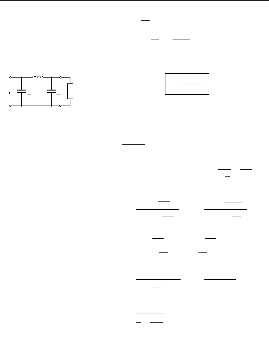
The same equation for the cut-off frequency is obtained for the low-pass
network shown in Figure 42.18 as follows:
C
2
C
2
Z
0
L
Z
0
Figure 42.18
From equation (41.3), for a symmetrical network,
Z
0
D
Z
1
Z
2
2
Z
1
C 2Z
2
Applying this to Figure 42.18 Z
1
D jωL and Z
2
D
1
jω
C
2
D
2
jωC
Thus Z
0
D
jωL
2
jωC
2
jωL C 2
2
jωC
D
jωL
4
ω
2
C
2
jωL j
4
ωC
D
j
4L
ωC
2
j
ωL
4
ωC
D
4L
ωC
2
4
ωC
ωL
D
4L
ωC
2
4
ωC
ωL
D
4L
4C ω
2
LC
2
i.e., Z
0
D
1
C
L
ω
2
C
2
4
42.4
Z
0
will be real if
C
L
>
ω
2
C
2
4
Filter networks 799
Thus attenuation will commence when
C
L
D
ω
2
C
2
4
i.e., when ω
2
c
D
4
LC
from which, cut-off frequency,
f
c
=
1
p
p
.LC/
as in equation (42.3)).
(b) Nominal impedance
When the frequency is very low, ω is small and the term ω
2
L
2
/4
in equation (42.1) (or the term ω
2
C
2
/4 in equation (42.4)) may be
neglected. The characteristic impedance then becomes equal to
p
L/C,
which is purely resistive. This value of the characteristic impedance is
known as the design impedance or the nominal impedance of the section
and is often given the symbol R
0
,
i.e.,
R
0
=
L
C
42.5
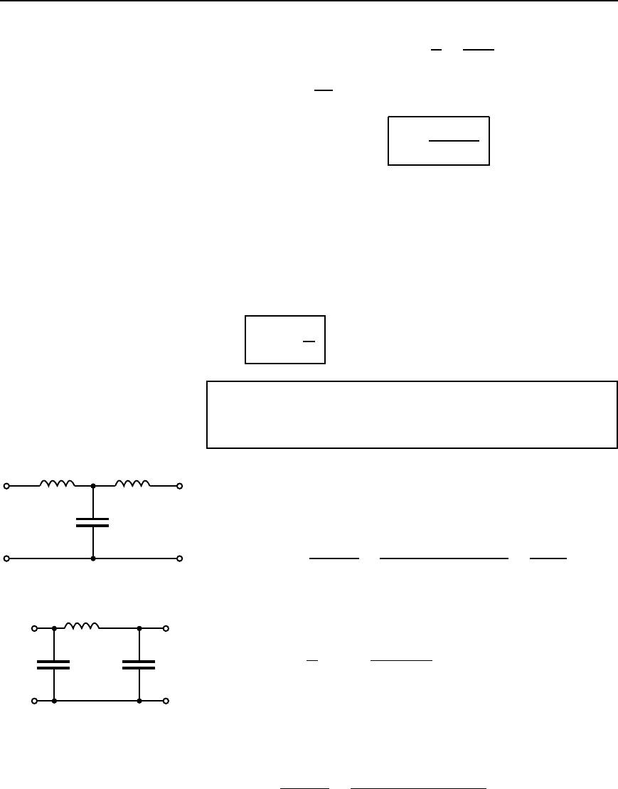
Problem 1. Determine the cut-off frequency and the nominal
impedance of each of the low-pass filter sections shown in
Figure 42.19.
(a) Comparing Figure 42.19(a) with the low-pass T section in
Figure 42.17 shows that L/2 D 100 mH, i.e., inductance,
L D 200 mH D 0.2 H and capacitance, C D 0.2
µF D 0.2 ð 10
6
F
From equation (42.3), cut-off frequency,
f
c
D
1
p
LC
D
1
0.2 ð 0.2 ð10
6
D
10
3
0.2
i.e., f
c
= 1592 Hz or 1.592 kHz
From equation (42.5), nominal impedance,
R
0
D
L
C
D
0.2
0.2 ð 10
6
D 1000 Z or 1kZ
(b) Comparing Figure 42.19(b) with the low-pass section shown
in Figure 42.18 shows that C/2 D 200 pF, i.e., capacitance,
C D 400 pF D 400 ð10
12
F and inductance, L D 0.4H,
From equation (42.3), cut-off frequency,
f
c
D
1
p
LC
D
1
0.4 ð 400 ð10
12
D 25.16 kHz
100 mH 100 mH
0.2 µF
0.4 H
200 pF 200 pF
(b)
(a)
Figure 42.19
800 Electrical Circuit Theory and Technology
From equation (42.5), nominal impedance,
R
0
D
L
C
D
0.4
400 ð 10
12
D 31.62 kZ
From equations (42.1) and (42.4) it is seen that the characteristic
impedance Z
0
varies with ω, i.e., Z
0
varies with frequency. Thus if
the nominal impedance is made to equal the load impedance into
which the filter feeds then the matching deteriorates as the frequency
increases from zero towards f
c
. It is however convention to make the
terminating impedance equal to the value of Z
0
well within the pass-
band, i.e., to take the limiting value of Z
0
as the frequency approaches
zero. This limit is obviously
p
L/C. This means that the filter is
properly terminated at very low frequency but as the cut-off frequency is
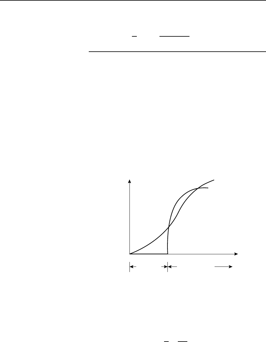
approached becomes increasingly mismatched. This is shown for a low-
pass section in Figure 42.20 by curve (a). It is seen that an increasing loss
is introduced into the pass band. Curve (b) shows the attenuation due to
the same low-pass section being correctly terminated at all frequencies. A
curve lying somewhere between curves (a) and (b) will usually result for
each section if several sections are cascaded and terminated in R
0
,orifa
matching section is inserted between the low pass section and the load.
Attenuation
(a)
(b)
0
f
c
Attenuation
band
Frequency
Pass band
Figure 42.20
(c) To determine values of L and C given R
0
and f
c
If the values of the nominal impedance R
0
and the cut-off frequency f
c
are known for a low pass T or section it is possible to determine the
values of inductance and capacitance required to form the section.
From equation (42.5), R
0
D
L
C
D
p
L
p
C
from which,
p
L D R
0
p
C
Filter networks 801
Substituting in equation (42.3) gives:
f
c
D
1
p
L
p
C
D
1
R
0
p
C
p
C
D
1
R
0
C
from which,
capacitance C =
1
pR
0
f
c
42.6
Similarly from equation (42.5),
p
C D
p
L
R
0
Substituting in equation (42.3) gives: f
c
D
1
p
L
p
L
R
0
D
R
0
L
from which,
inductance, L =
R
0
pf
c
42.7
Problem 2. A filter section is to have a characteristic impedance at
zero frequency of 600 and a cut-off frequency at 5 MHz. Design
(a) a low-pass T section filter, and (b) a low-pass section filter
to meet these requirements.
The characteristic impedance at zero frequency is the nominal impedance
R
0
, i.e., R
0
D 600 ; cut-off frequency, f
c
D 5MHzD 5 ð 10
6
Hz.
From equation (42.6),
capacitance, C D
1
R
0
f
c
D
1
6005 ð 10
6
F D 106 pF
and from equation (42.7),
inductance, L D
R
0
f
c
D
600
5 ð 10
6
H D 38.2
µH
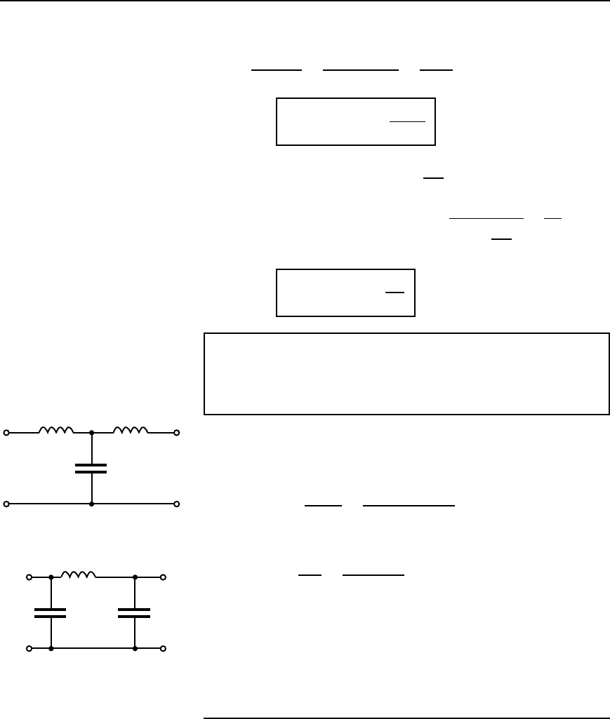
(a) A low-pass T section filter is shown in Figure 42.21(a), where
the series arm inductances are each L/2 (see Figure 42.17), i.e.,
38.2/2 D 19.1
µH
(b) A low-pass section filter is shown in Figure 42.21(b), where
the shunt arm capacitances are each C/2 (see Figure 42.18), i.e.,
106/2 D 53 pF
19.1 µH
106 pF
(a)
38.2 µH
53 pF 53 pF
(b)
19.1 µH
Figure 42.21
(d) ‘Constant-k’ prototype low-pass filter
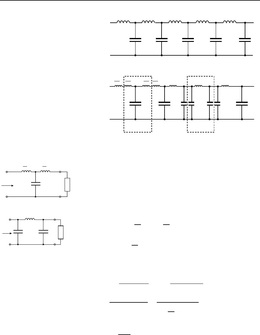
A ladder network is shown in Figure 42.22, the elements being expressed
in terms of impedances Z
1
and Z
2
. The network shown in Figure 42.22(b)
802 Electrical Circuit Theory and Technology
Z
1
Z
1
Z
1
Z
1
Z
1
Z
2
Z
2
Z
2
Z
2
Z
2
AD FH
BE GJ
Z
1
2
Z
1
2
Z
1
2
Z
1
2
Z
1
Z
1
Z
1
Z
2
Z
2
2Z
2
2Z
2
2Z
2
2Z
2
Z
2
(a)
(b)
Figure 42.22
is equivalent to the network shown in Figure 42.22(a), where Z
1
/2 in
series with Z
1
/2 equals Z
1
and 2Z
2
in parallel with 2Z
2
equals Z
2
.
Removing sections ABED and FGJH from Figure 42.22(b) gives the T
section shown in Figure 42.23(a), which is terminated in its characteristic
impedance Z
OT
, and the section shown in Figure 42.23(b), which is
terminated in its characteristic impedance Z
0
.
Z
1
2
Z
1
2
Z
2
Z
0T
Z
0T
(a)
Z
1
Z
0p
2Z
2
2Z
2
Z
0p
(b)
Figure 42.23
From equation (41.1), page 760,
Z
OT
D
Z
1
2
2
C 2
Z
1
2
Z
2
i.e., Z
OT
D
Z
2
1
4
C Z
1
Z
2
42.8
From equation (41.3), page 760
Z
0
D
Z
1
2Z
2
2
Z
1
C 22Z
2
D
Z
1
Z
1
4Z
2
2
Z
1
Z
1
C 4Z
2
D
2Z
1
Z
2
Z
2
1
C 4Z
1
Z
2
D
Z
1
Z
2
Z
2
1
4
C Z
1
Z
2
i.e., Z
0
D
Z
1
Z
2
Z
OT
from equation (42.8)

Filter networks 803
Thus
Z
0T
Z
0p
= Z
1
Z
2
42.9
This is a general expression relating the characteristic impedances of T
and sections made up of equivalent series and shunt impedances.
From the low-pass sections shown in Figures 42.17 and 42.18,
Z
1
D jωL and Z
2
D
1
jωC
.
Hence Z
0T
Z
0
D jωL
1
jωC
D
L
C
Thus, from equation (42.5),
Z
0T
Z
0p
= R
2
0
42.10
From equations (42.9) and (42.10),
Z
0T
Z
0
D Z
1
Z
2
D R
2
0
D constant (k).
A ladder network composed of reactances, the series reactances being
of opposite sign to the shunt reactances (as in Figure 42.23) are called
‘constant-k’ filter sections. Positive (i.e., inductive) reactance is directly
proportional to frequency, and negative (i.e., capacitive) reactance is
inversely proportional to frequency. Thus the product of the series and
shunt reactances is independent of frequency (see equations (42.9) and
(42.10)). The constancy of this product has given this type of filter
its name.
From equation (42.10), it is seen that Z
0T
and Z
0
will either be both
real or both imaginary together (since j
2
D1). Also, when Z
0T
changes
from real to imaginary at the cut-off frequency, so will Z
0
. The two
sections shown in Figures 42.17 and 42.18 will thus have identical cut-
off frequencies and thus identical pass bands. Constant-k sections of any
kind of filter are known as prototypes.
(e) Practical low-pass filter characteristics
From equation (42.1), the characteristic impedance Z
0T
of a low-pass T
section is given by:
Z
0T
D
L
C
ω
2
L
2
4
Rearranging gives:
Z
0T
D
L
C
1
ω
2
LC
4
D
L
C
1
ω
2
LC
4
D R
0
1
ω
2
LC
4
from equation (42.5)

804 Electrical Circuit Theory and Technology
From equation (42.2), ω
2
c
D
4
LC
, hence Z
0T
D R
0
1
ω
2
ω
2
c
i.e.,
Z
0T
= R
0
1 −
!
!
c
2
42.11
Also, from equation (42.10), Z
0
D
R
2
0
Z
0T
D
R
2
0
R
0
1
ω
ω
c
2
i.e.,
Z
0p
=
R
0
1 −
!
!
c
2
42.12
(Alternatively, the expression for Z
0
could have been obtained from
equation (42.4), where
Z
0
D
1
C
L
ω
2
C
2
4
D
L
C
L
C
C
L
ω
2
C
2
4
D
L
C
1
ω
2
LC
4
D
R
0
1
ω
ω
c
2
as above.
From equations (42.11) and (42.12), when ω D 0 (i.e., when the frequency
is zero),
Z
0T
D Z
0
D R
0
.
At the cut-off frequency, f
c
, ω D ω
c
and from equation (42.11), Z
0T
falls to zero,
and from equation (42.12), Z
0
rises to infinity.
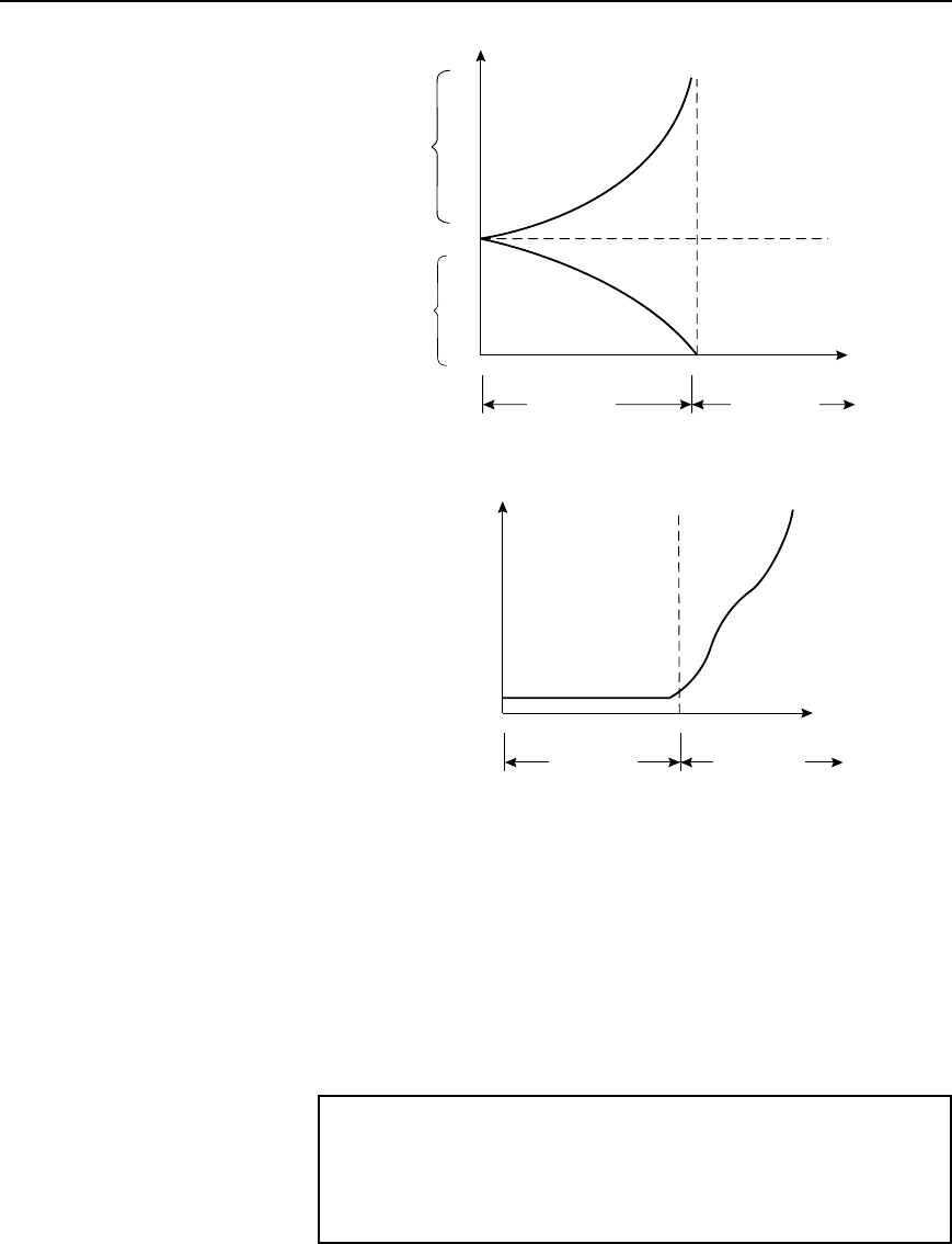
These results are shown graphically in Figure 42.24, where it is seen
that Z
0T
decreases from R
0
at zero frequency to zero at the cut-off
frequency; Z
0
rises from its initial value of R
0
to infinity at f
c
.
(At a frequency, f D 0.95f
c
, for example, Z
0
D
R
0
1 0.95
2
D 3.2R
0
from equation (42.12)).
Filter networks 805
Nominal
Impedance
Frequency
Attenuation
band
R
0
Z
0T
Z
0p
Z
0
0
f
c
Pass band
Figure 42.24
Frequency
Attenuation
Band
Pass band
0
f
c
Attenuation
Figure 42.25
Note that since Z
0
becomes purely reactive in the attenuation band, it is
not shown in this range in Figure 42.24.
Figure 42.2(a), on page 791, showed an ideal low-pass filter section
characteristic. In practise, the characteristic curve of a low-pass prototype
filter section looks more like that shown in Figure 42.25. The character-
istic may be improved somewhat closer to the ideal by connecting two
or more identical sections in cascade. This produces a much sharper cut-
off characteristic, although the attenuation in the pass band is increased
a little.
Problem 3. The nominal impedance of a low-pass section filter
is 500 and its cut-off frequency is at 100 kHz. Determine (a) the
value of the characteristic impedance of the section at a frequency
of 90 kHz, and (b) the value of the characteristic impedance of the
equivalent low-pass T section filter.

806 Electrical Circuit Theory and Technology
At zero frequency the characteristic impedance of the and T section
filters will be equal to the nominal impedance of 500 .
(a) From equation (42.12), the characteristic impedance of the section
at 90 kHz is given by:
Z
0
D
R
0
1
ω
ω
c
2
D
500
1
290 ð 10
3
2100 ð 10
3
2
D
500
[1 0.9
2
]
D 1147 Z
(b) From equation (42.11), the characteristic impedance of the T section
at 90 kHz is given by:
Z
0T
D R
0
1
ω
ω
c
2
D 500
[1 0.9
2
] D 218 Z
(Check: From equation (42.10),
Z
0T
Z
0
D 2181147 D 250000 D 500
2
D R
2
0
Typical low-pass characteristics of characteristic impedance against
frequency are shown in Figure 42.24.
Problem 4. A low-pass section filter has a nominal impedance
of 600 and a cut-off frequency of 2 MHz. Determine the
frequency at which the characteristic impedance of the section is
(a) 600 (b)1k (c) 10 k
From equation (42.12), Z
0
D
R
0
1
ω
ω
c
2
(a) When Z
0
D 600 and R
0
D 600 , then ω D 0, i.e., the
frequency is zero
(b) When Z
0
D 1000 , R
0
D 600 and f
c
D 2 ð10
6
Hz
then 1000 D
600
1
2f
22 ð 10
6
2

Filter networks 807
from which, 1
f
2 ð 10
6
2
D
600
1000
2
D 0.36
and
f
2 ð 10
6
D
p
1 0.36 D 0.8
Thus when Z
0
D 1000 ,
frequency, f D 0.82 ð10
6
D 1.6MHz
(c) When Z
0
D 10 k, then
10000 D
600
1
f
2
2
,
where frequency,
f is in megahertz.
Thus 1
f
2
2
D
600
10000
2
D 0.06
2
and
f
2
D
[1 0.06
2
] D 0.9982
Hence when Z
0
D 10 k, frequency f D 20.9982
D 1.996 MHz
The above three results are seen to be borne out in the characteristic of
Z
0
against frequency shown in Figure 42.24.
Further problems on low-pass filter sections may be found in
Section 42.10, problems 1 to 6, page 837.
42.6 High-pass filter
sections
(a) The cut-off frequency
High-pass T and sections are shown in Figure 42.26, (as derived in
Section (42.4)), each being terminated in their characteristic impedance.
From equation (41.1), page 760, the characteristic impedance of a T
section is given by:
Z
0T
D
Z
2
A
C 2Z
A
Z
B
From Figure 42.26(a), Z
A
D
1
jω2C
and Z
B
D jωL
Thus Z
0T
D
1
jω2C
2
C 2
1
jω2C
jωL
