Bird J. Electrical Circuit Theory and Technology
Подождите немного. Документ загружается.

818 Electrical Circuit Theory and Technology
(b) D 1.794
6
39.4
°
D 1.794[cos39.4
°
C j sin39.4
°
]
D 1.386 j1.139
Hence (i) the attenuation coefficient, a
= 1.386 N
and (ii) the phase shift coefficient, b
= −1.139 rad
Problem 10. The current input to a filter section is 24
6
10
°
mA and
the current output is 8
6
45
°
mA. Determine for the section (a) the
attenuation coefficient, (b) the phase shift coefficient, and (c) the
propagation coefficient. (d) If five such sections are cascaded
determine the output current of the fifth stage and the overall
propagation constant of the network.
Let I
1
D 24
6
10
°
mA and I
2
D 8
6
45
°
mA, then
I
1
I
2
D
24
6
10
°
8
6
45
°
D 3
6
55
°
D e
˛
6
ˇ from equation (42.25).
(a) Hence the attenuation constant, ˛, is obtained from 3 D e
˛
, i.e.,
a
= ln 3 = 1.099 N
(b) The phase shift coefficient ˇ D 55
°
ð
180
D 0.960 rad
(c) The propagation coefficient D ˛ C jˇ D .1.099 Y j0.960/ or
1.459
66
41.14
°
(d) If I
6
is the current output of the fifth stage, then from
equation (42.26),
I
1
I
6
D e
n
D [3
6
55
°
]
5
D 243
6
275
°
(by De Moivre’s theorem)
Thus the output current of the fifth stage,
I
6
D
I
1
243
6
275
°
D
24
6
10
°
243
6
275
°
= 0.0988
66
−265
°
mA or 98.8
66
95
°
mA
Let the overall propagation coefficient be
0
then
I
1
I
6
D 243
6
275
°
D e
0
D e
˛
0
6
ˇ
0
The overall attenuation coefficient ˛
0
D ln243 D 5.49
and the overall phase shift coefficient ˇ
0
D 275
°
ð
180
°
D 4.80 rad
Hence the overall propagation coefficient g
0
D .5.49 Y j4.80/ or
7.29
66
41.16
°
Filter networks 819
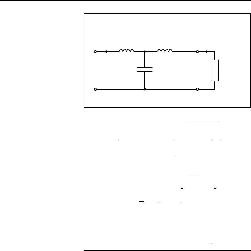
Problem 11. For the low-pass T section filter shown in
Figure 42.34 determine (a) the attenuation coefficient, (b) the phase
shift coefficient and (c) the propagation coefficient .
I
1
X
L
= j5 Ω X
L
= j5 Ω
I
2
X
C
=−j10 Ω
R
L
= 12 Ω
Figure 42.34
By current division in Figure 42.34, I
2
D
X
C
X
C
C X
L
C R
L
I
1
from which
I
1
I
2
D
X
C
C X
L
C R
L
X
C
D
j10 C j5 C 12
j10
D
j5 C12
j10
D
j5
j10
C
12
j10
D 0.5 C
j12
j
2
10
D 0.5 C j1.2
D 1.3
6
67.38
°
or 1.3
6
1.176
From equation (42.25),
I
1
I
2
D e
˛
6
ˇ D 1.3
6
1.176
(a) The attenuation coefficient, ˛ D ln1.3 D 0.262 N
(b) The phase shift coefficient, b D 1.176 rad
(c) The propagation coefficient, D ˛ C jˇ D .0.262 Y j1.176/ or
1.205
66
77.44
°
Variation in phase angle in the pass-band of a filter
In practise, the low and high-pass filter sections discussed in Sections 42.5
and 42.6 would possess a phase shift between the input and output volt-
ages which varies considerably over the range of frequency comprising
the pass-band.
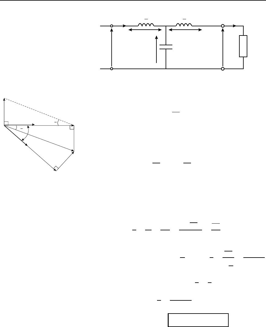
Let the low-pass prototype T section shown in Figure 42.35 be termi-
nated as shown in its nominal impedance R
0
. The input impedance for
frequencies much less than the cut-off frequency is thus also equal to R
0
and is resistive. The phasor diagram representing Figure 42.35 is shown
in Figure 42.36 and is produced as follows:
820 Electrical Circuit Theory and Technology
I
1
L
2
L
2
V
L1
V
L2
V
C
V
1
C
V
2
R
0
I
2
Figure 42.35
(i) V
1
and I
1
are in phase (since the input impedance is resistive).
(ii) Voltage V
L1
D I
1
X
L
D I
1
ωL
2
, which leads I by 90
°
.
(iii) Voltage V
1
is the phasor sum of V
L1
and V
C
. Thus V
C
is drawn
as shown, completing the parallelogram oabc.
(iv) Since no power is dissipated in reactive elements V
1
D V
2
in
magnitude.
(v) Voltage V
L2
D I
2
ωL
2
D I
1
ωL
2
D V
L1
(vi) Voltage V
C
is the phasor sum of V
L2
and V
2
as shown by triangle
ocd, where V
L2
is at right angles to V
2
a
V
L
1
0
b
2
I
1
b
2
b
V
1
V
C
c
V
L
2
I
2
V
2
d
b
Figure 42.36
(vii) Current I
2
is in phase with V
2
since the output impedance is resis-
tive. The phase lag over the section is the angle between V
1
and
V
2
shown as angle ˇ in Figure 42.36,
where tan
ˇ
2
D
oa
ob
D
V
L1
V
1
D
I
1
ωL
2
I
1
R
0
D
ωL
2
R
0
From equation (42.5), R
0
D
L
C
, thus tan
ˇ
2
D
ωL
2
L
C
D
ω
p
LC
2
For angles of ˇ up to about 20
°
,tan
ˇ
2
³
ˇ
2
radians
Thus when ˇ<20
°
,
ˇ
2
D
ω
p
LC
2
from which, phase angle,
b = !
p
.LC/ radian
42.27
Since ˇ D 2f
p
LC D 2
p
LCf then ˇ is proportional to f and a
graph of ˇ (vertical) against frequency (horizontal) should be a straight
Filter networks 821
line of gradient 2
p
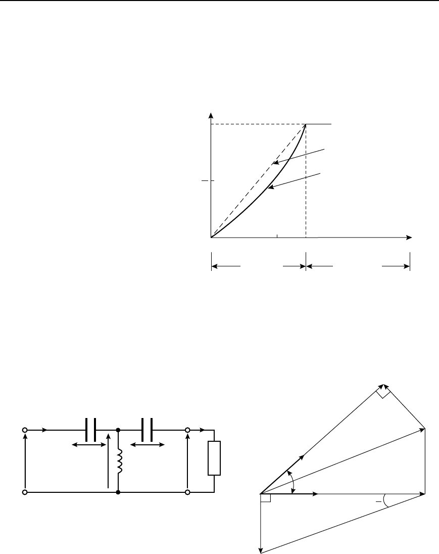
LC and passing through the origin. However in
practise this is only usually valid up to a frequency of about 0.7 f
c
for a
low-pass filter and a typical characteristic is shown in Figure 42.37. At the
cut-off frequency, ˇ D rad. For frequencies within the attenuation band,
the phase shift is unimportant, since all voltages having such frequencies
are suppressed.
p
Phase angle
b (rad)
p
2
0
0.7 f
c
Frequency
Ideal characteristic
Practical curve
Pass band
Attenuation
band
f
c
Figure 42.37
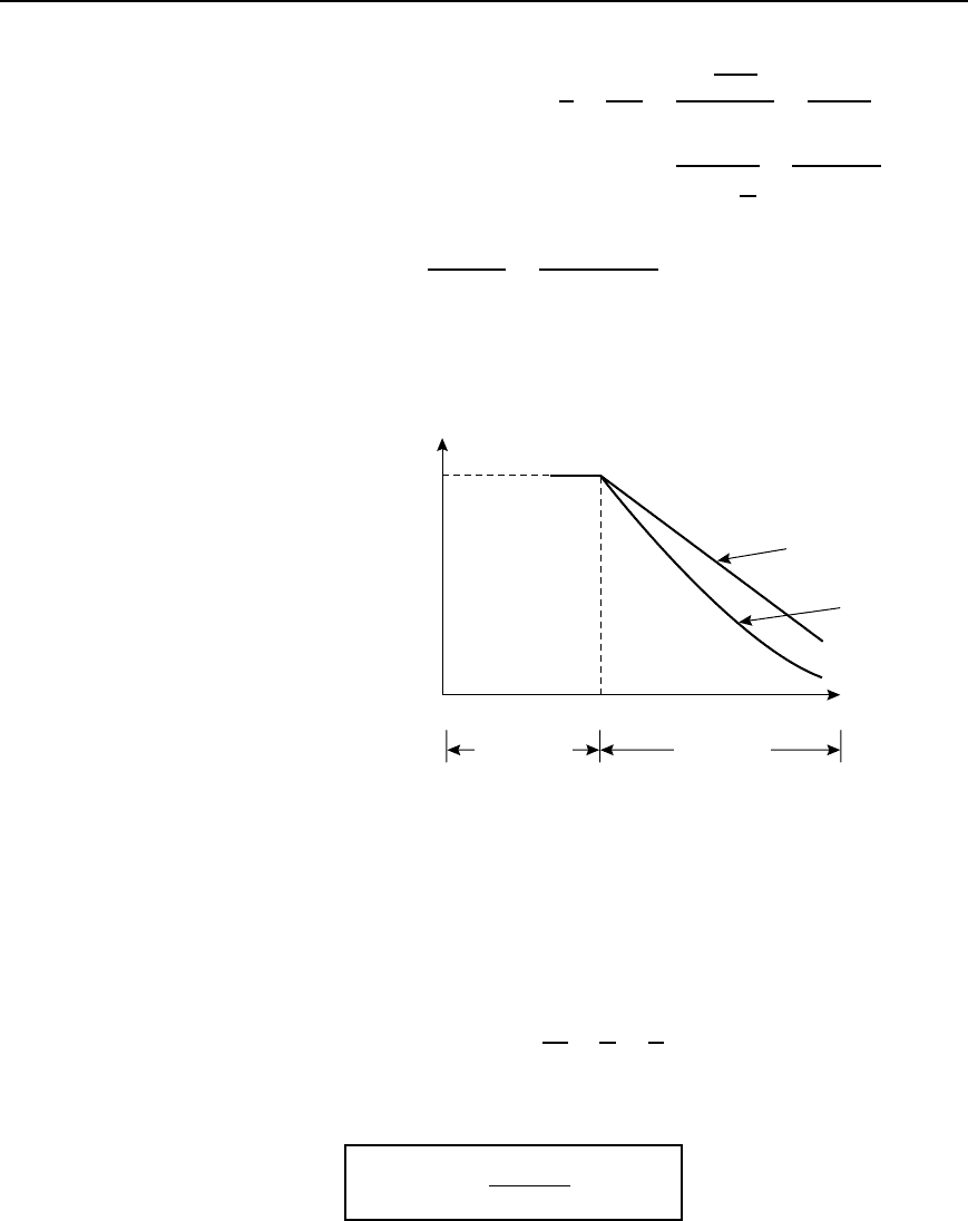
A high-pass prototype T section is shown in Figure 42.38(a) and its
phasor diagram in Figure 42.38(b), the latter being produced by similar
reasoning to above.
I
1
2C 2C
I
2
V
C
1
V
C
2
V
L
L
V
1
V
2
R
0
(a)
I
2
V
2
V
C
2
b
I
1
V
L
V
1
V
C
1
(b)
b
2
Figure 42.38
822 Electrical Circuit Theory and Technology
From Figure 42.38(b), tan
ˇ
2
D
V
C1
V
1
D
I
1
1
ω2C
I
1
R
0
D
1
2ωCR
0
D
1
2ωC
L
C
D
1
2ω
p
LC
i.e., ˇ D
1
ω
p
LC
D
1
2
p
LCf
for small angles.
Thus the phase angle is universely proportional to frequency. The ˇ/f
characteristics of an ideal and a practical high-pass filter are shown in
Figure 42.39.
0 f
c
Frequency
p
Phase
angle
b (rad)
Ideal
characteristic
Practical
curve
Attenuation
band
Pass band
Figure 42.39
Time delay
The change of phase that occurs in a filter section depends on the time
the signal takes to pass through the section. The phase shift ˇ may be
expressed as a time delay. If the frequency of the signal is f then the
periodic time is 1/f seconds.
Hence the time delay D
ˇ
2
ð
1
f
D
ˇ
ω
.
From equation (42.27), ˇ D ω
p
LC. Thus
time delay =
!
p
.LC/
!
=
p
.LC/
42.28
when angle ˇ is small.

Filter networks 823
Equation (42.28) shows that the time delay, or transit time,is
independant of frequency. Thus a phase shift which is proportional to
frequency (equation (42.27)) results in a time delay which is independant
of frequency. Hence if the input to the filter section consists of a complex
wave composed of several harmonic components of differing frequency,
the output will consist of a complex wave made up of the sum of
corresponding components all delayed by the same amount. There will
therefore be no phase distortion due to varying time delays for the separate
frequency components.
In practise, however, phase shift ˇ tends not to be constant and the
increase in time delay with rising frequency causes distortion of non-
sinusoidal inputs, this distortion being superimposed on that due to the
attenuation of components whose frequency is higher than the cut-off
frequency.
At the cut-off frequency of a prototype low-pass filter, the phase angle
ˇ D rad. Hence the time delay of a signal through such a section at the
cut-off frequency is given by
ˇ
ω
D
2f
c
D
1
2f
c
D
1
2
1
p
LC
from equation (42.3),
i.e., at f
c
,
the transit time =
p
p
.LC/
2
seconds
42.29
Problem 12. Determine for the filter section shown in Figure 42.40,
(a) the time delay for the signal to pass through the filter, assuming
the phase shift is small, and (b) the time delay for a signal to pass
through the section at the cut-off frequency.
Comparing Figure 42.40 with the low-pass T section of Figure 42.13(a),
shows that
L
2
D 0.5 H, thus inductance L D 1 H, and capacitance C D 2nF
0.5 H 0.5 H
2 nF
Figure 42.40
(a) From equation (42.28),
time delay D
p
LC D
p
[12 ð 10
9
] D 44.7 ms
(b) From equation (42.29), at the cut-off frequency,
time delay D
2
p
LC D
2
44.7 D 70.2 ms

824 Electrical Circuit Theory and Technology
Problem 13. A filter network comprising n identical sections
passes signals of all frequencies up to 500 kHz and provides a
total delay of 9.55
µs. If the nominal impedance of the circuit into
which the filter is inserted is 1 k, determine (a) the values of the
elements in each section, and (b) the value of n.
Cut-off frequency, f
c
D 500 ð 10
3
Hz and nominal impedance
R
0
D 1000 .
Since the filter passes frequencies up to 500 kHz then it is a low-pass
filter.
(a) From equations (42.6) and (42.7), for a low-pass filter section,
capacitance, C D
1
R
0
f
c
D
1
1000500 ð 10
3
636.6pF
and inductance, L D
R
0
f
c
D
1000
500 ð 10
3
636.6 mH
Thus if the section is a low-pass T section then the inductance in
each series arm will be L/2 D 318.3 mH and the capacitance in
the shunt arm will be 636.6 pF.
If the section is a low-pass p section then the inductance in the
series arm will be 636.6 mH and the capacitance in each shunt arm
will be C/2 D 318.3pF
(b) From equation (42.28), the time delay for a single section
D
p
LC D
p
[636.6 ð 10
6
636.6 ð 10
12
] D 0.6366 µs
For a time delay of 9.55
µs therefore, the number of cascaded
sections required is given by
9.55
0.6366
D 15, i.e., n
= 15
Problem 14. A filter network consists of 8 sections in cascade
having a nominal impedance of 1 k. If the total delay time is
4
µs, determine the component values for each section if the filter
is (a) a low-pass T network, and (b) a high-pass network.
Since the total delay time is 4 µs then the delay time of each of the 8
sections is
4
8
, i.e., 0.5 µs
From equation (42.28), time delay D
p
LC
Hence 0.5 ð 10
6
D
p
LC (i)
Filter networks 825
Also, from equation (42.5),
L
C
D 1000 (ii)
From equation (ii),
p
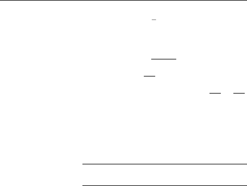
L D 1000
p
C
Substituting in equation (i) gives: 0.5 ð10
6
D 1000
p
C
p
C D 1000 C
from which, capacitance C D
0.5 ð 10
6
1000
D 0.5nF
From equation (ii),
p
C D
p
L
1000
Substituting in equation (i) gives: 0.5 ð 10
6
D
p
L
p
L
1000
D
L
1000
from which, inductance, L D 500
µH
(a) If the filter is a low-pass T section then, from Figure 42.13(a), each
series arm has an inductance of L/2, i.e., 250 mH and the shunt arm
has a capacitance of 0.5 nF
(b) If the filter is a high-pass p network then, from Figure 42.16(b),
the series arm has a capacitance of 0.5 nF and each shunt arm has
an inductance of 2 L, i.e., 1000 mHor1mH.
Further problems on propagation coefficient and time delay may be found
in Section 42.10, problems 13 to 18, page 838
42.8 ‘m-derived’ filter
sections
(a) General
In a low-pass filter a clearly defined cut-off frequency followed by a high
attenuation is needed; in a high-pass filter, high attenuation followed by a
clearly defined cut-off frequency is needed. It is not practicable to obtain
either of these conditions by wiring appropriate prototype constant-k
sections in cascade. An equivalent section is therefore required having:
(i) the same cut-off frequency as the prototype but with a rapid rise in
attenuation beyond cut-off for a low-pass type or a rapid decrease
at cut-off from a high attenuation for the high-pass type,
(ii) the same value of nominal impedance R
0
as the prototype at
all frequencies (otherwise the two forms could not be connected
together without mismatch).
If the two sections, i.e., the prototype and the equivalent section, have the
same value of R
0
they will have identical pass-bands.
The equivalent section is called an ‘m-derived’ filter section (for
reasons as explained below) and is one which gives a sharper cut-off
at the edges of the pass band and a better impedance characteristic.
826 Electrical Circuit Theory and Technology
Z
1
2
Z
1
2
Z
2
mZ
1
2
mZ
1
2
Z ′
2
(a)
(b)
Figure 42.41
(b) T sections
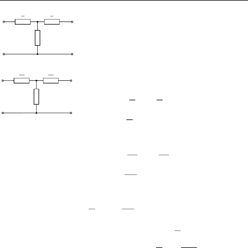
A prototype T section is shown in Figure 42.41(a). Let a new section be
constructed from this section having a series arm of the same type but of
different value, say mZ
1
, where m is some constant. (It is for this reason
that the new equivalent section is called an ‘m-derived’ section.) If the
characteristic impedance Z
0T
of the two sections is to be the same then
the value of the shunt arm impedance will have to be different to Z
2
.
Let this be Z
0
2
as shown in Figure 42.41(b).
The value of Z
0
2
is determined as follows:
From equation (41.1), page 760, for the prototype shown in Fig-
ure 42.41(a):
Z
0T
D
Z
1
2
2
C 2
Z
1
2
Z
2
i.e., Z
0T
D
Z
2
1
4
C Z
1
Z
2
(a)
Similarly, for the new section shown in Figure 42.41(b),
Z
0T
D
mZ
1
2
2
C 2
mZ
1
2
Z
0
2
i.e., Z
0T
D
m
2
Z
2
1
4
C mZ
1
Z
0
2
(b)
Equations (a) and (b) will be identical if:
Z
2
1
4
C Z
1
Z
2
D
m
2
Z
2
1
4
C mZ
1
Z
0
2
Rearranging gives: mZ
1
Z
0
2
D Z
1
Z
2
C
Z
2
1
4
1 m
2
i.e., Z
0
2
D
Z
2
m
C Z
1
1 m
2
4m
42.30
Thus impedance Z
0
2
consists of an impedance Z
2
/m in series with an
impedance Z
1
1 m
2
/4m. An additional component has therefore been
introduced into the shunt arm of the m-derived section. The value of m
can range from 0 to 1, and when m D 1, the prototype and the m-derived
sections are identical.
(c) p sections
A prototype section is shown in Figure 42.42(a). Let a new section be
constructed having shunt arms of the same type but of different values,
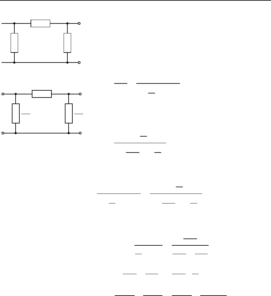
Filter networks 827
Z
1
2Z
2
2Z
2
Z ′
1
2Z
2
m
2Z
2
m
(a)
(b)
Figure 42.42
say Z
2
/m, where m is some constant. If the characteristic impedance Z
0
of the two sections is to be the same then the value of the series arm
impedance will have to be different to Z
1
.
Let this be Z
0
1
as shown in Figure 42.42(b).
The value of Z
0
1
is determined as follows:
From equation (42.9), Z
0T
Z
0
D Z
1
Z
2
Thus the characteristic impedance of the section shown in
Figure 42.42(a) is given by:
Z
0
D
Z
1
Z
2
Z
0T
D
Z
1
Z
2
Z
2
1
4
C Z
1
Z
2
(c)
from equation (a) above.
For the section shown in Figure 42.42(b),
Z
0
D
Z
0
1
Z
2
m
Z
0
1
2
4
C Z
0
1
Z
2
m
(d)
Equations (c) and (d) will be identical if
Z
1
Z
2
Z
2
1
4
C Z
1
Z
2
D
Z
0
1
Z
2
m
Z
0
1
2
4
C Z
0
1
Z
2
m
Dividing both sides by Z
2
and then squaring both sides gives:
Z
2
1
Z
2
1
4
C Z
1
Z
2
D
Z
0
1
2
m
2
Z
0
1
2
4
C
Z
0
1
Z
2
m
Thus Z
2
1
Z
0
1
2
4
C
Z
0
1
Z
2
m
D
Z
0
1
2
m
2
Z
2
1
4
C Z
1
Z
2
i.e.,
Z
2
1
Z
0
1
2
4
C
Z
2
1
Z
0
1
Z
2
m
D
Z
0
1
2
Z
2
1
4m
2
C
Z
0
1
2
Z
1
Z
2
m
2
Multiplying throughout by 4m
2
gives:
m
2
Z
2
1
Z
0
1
2
C 4mZ
2
1
Z
0
1
Z
2
D Z
0
1
2
Z
2
1
C 4Z
0
1
2
Z
1
Z
2
Dividing throughout by Z
0
1
and rearranging gives:
4mZ
2
1
Z
2
D Z
0
1
Z
2
1
C 4Z
1
Z
2
m
2
Z
2
1
