Bird J. Electrical Circuit Theory and Technology
Подождите немного. Документ загружается.


848 Electrical Circuit Theory and Technology
Problem 7. Two coils are connected in series and their effective
inductance is found to be 15 mH. When the connection to one coil
is reversed, the effective inductance is found to be 10 mH. If the
coefficient of coupling is 0.7, determine (a) the self inductance of
each coil, and (b) the mutual inductance.
(a) From equation (43.13), total inductance, L D L
1
C L
2
š 2M
and from equation (43.9), M D k
p
L
1
L
2
hence L D L
1
C L
2
š 2k
p
L
1
L
2
Since in equation (43.11),
L
A
D 15 mH, 15 D L
1
C L
2
C 2k
p
L
1
L
2
43.15
and since in equation (43.12),
L
B
D 10 mH, 10 D L
1
C L
2
2k
p
L
1
L
2
43.16
Equation 43.15 C equation (43.16) gives:
25 D 2L
1
C 2L
2
and 12.5 D L
1
C L
2
43.17
From equation (43.17), L
2
D 12.5 L
1
Substituting in equation (43.15), gives:
15 D L
1
C 12.5 L
1
C 20.7
p
[L
1
12.5 L
1
]
i.e., 15 D 12.5 C 1.4
12.5L
1
L
2
1
15 12.5
1.4
D
12.5L
1
L
2
1
and
15 12.5
1.4
2
D 12.5L
1
L
2
1
i.e., 3.189 D 12.5L
1
L
2
1
from which, L
2
1
12.5L
1
C 3.189 D 0
Using the quadratic formula:
L
1
D
12.5 š
[12.5
2
413.189]
21
i.e., L
1
D
12.5 š 11.98
2
D 12.24 mH or 0.26 H
From equation (43.17):
L
2
D 12.5 L
1
D 12.5 12.24 D 0.26 mH
or 12.5 0.26 D 12.24 mH
Magnetically coupled circuits 849
(b) From equation (43.14),
mutual inductance, M D
L
A
L
B
4
D
15 10
4
D 1.25 mH
Further problems on coils in series may be found in Section 43.8, problems
7 to 11, page 865.
43.6 Coupled circuits
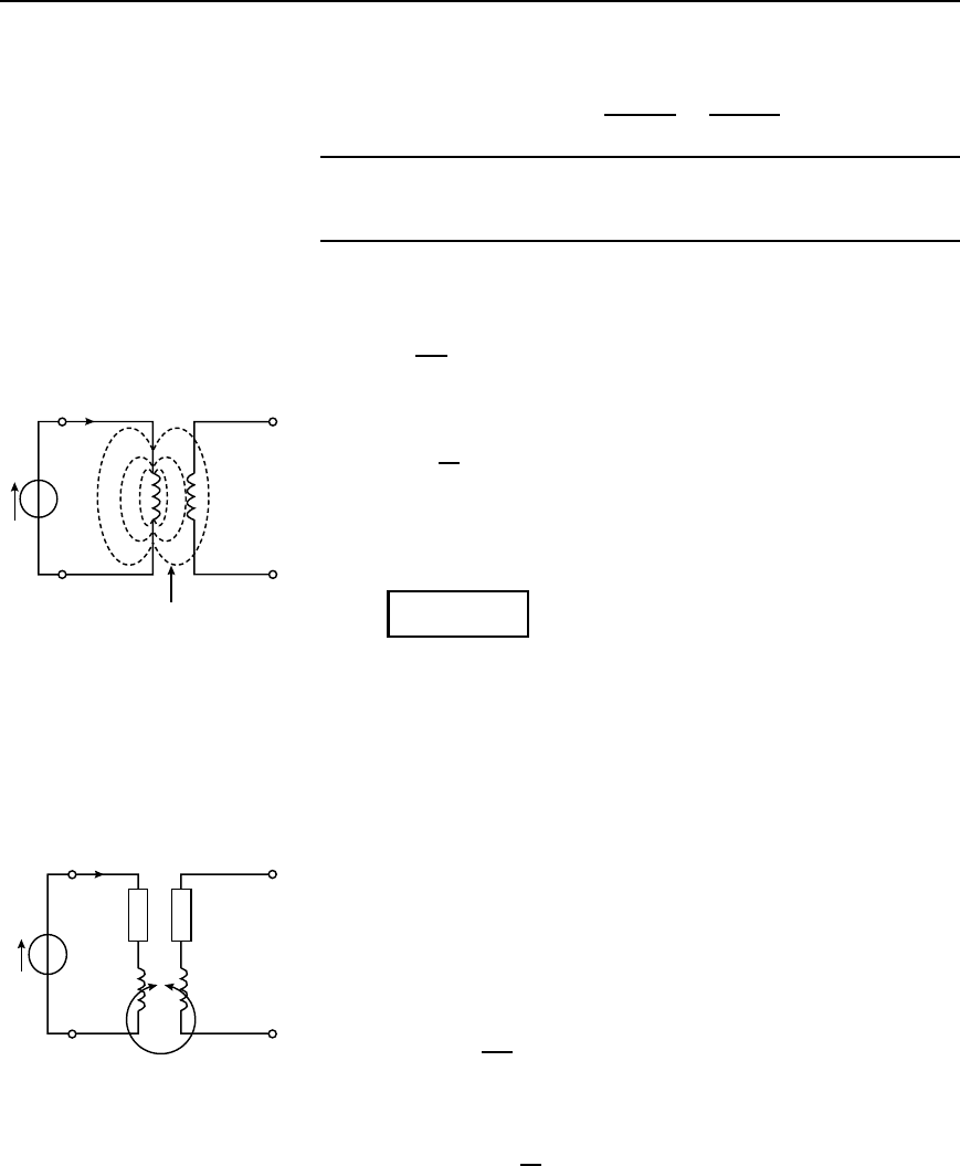
The magnitude of the secondary e.m.f. E
2
in Figure 43.5 is given by:
E
2
D M
dI
1
dt
, from equation (43.1)
If the current I
1
is sinusoidal, i.e., I
1
D I
1m
sinωt
then E
2
D M
d
dt
I
1m
sinωt D MωI
1m
cosωt
Since cos ωt D sinωt C 90
°
then cosωt D j sinωt in complex form.
Hence E
2
D MωI
1m
j sin ωt D jωMI
1m
sinωt
i.e.,
E
2
= j!MI
1
43.18
E
1
I
1
E
2
Magnetic flux
Figure 43.5
If L
1
is the self inductance of the primary winding in Figure 43.5, there
will be an e.m.f. generated equal to jωL
1
I
1
induced into the primary
winding since the flux set up by the primary current also links with the
primary winding.
(a) Secondary open-circuited
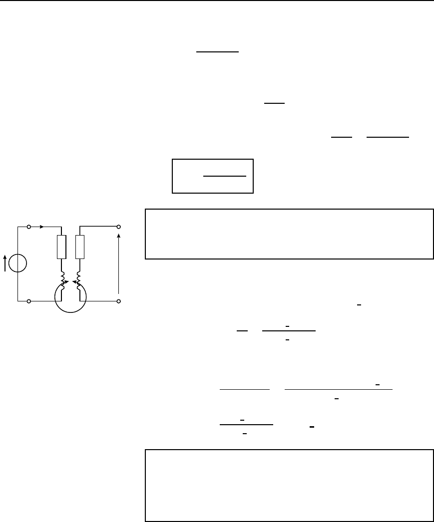
Figure 43.6 shows two coils, having self inductances of L
1
and L
2
which
are inductively coupled together by a mutual inductance M. The primary
winding has a voltage generator of e.m.f. E
1
connected across its termi-
nals. The internal resistance of the source added to the primary resistance
is shown as R
1
and the secondary winding which is open-circuited has a
resistance of R
2
.
Applying Kirchhoff’s voltage law to the primary circuit gives:
E
1
D I
1
R
1
C L
1
dI
1
dt
43.19
I
1
R
1
R
2
E
1
L
1
L
2
M
Figure 43.6
If E
1
and I
1
are both sinusoidal then equation (43.19) becomes:
E
1
D I
1
R
1
C L
1
d
dt
I
1m
sinωt
D I
1
R
1
C L
1
ωI
1m
cosωt
D I
1
R
1
C L
1
ωjI
1m
sinωt
850 Electrical Circuit Theory and Technology
i.e., E
1
D I
1
R
1
C jωI
1
L
1
D I
1
R
1
C jωL
1
i.e., I
1
D
E
1
R
1
C jωL
1
43.20
From equation (43.18), E
2
D jωMI
1
from which, I
1
D
E
2
jωM
43.21
Equating equations (43.20) and (43.21) gives:
E
2
j!M
D
E
1
R
1
C j!L
1
and
E
2
=
j!ME
1
R
1
Y j!L
1
43.22
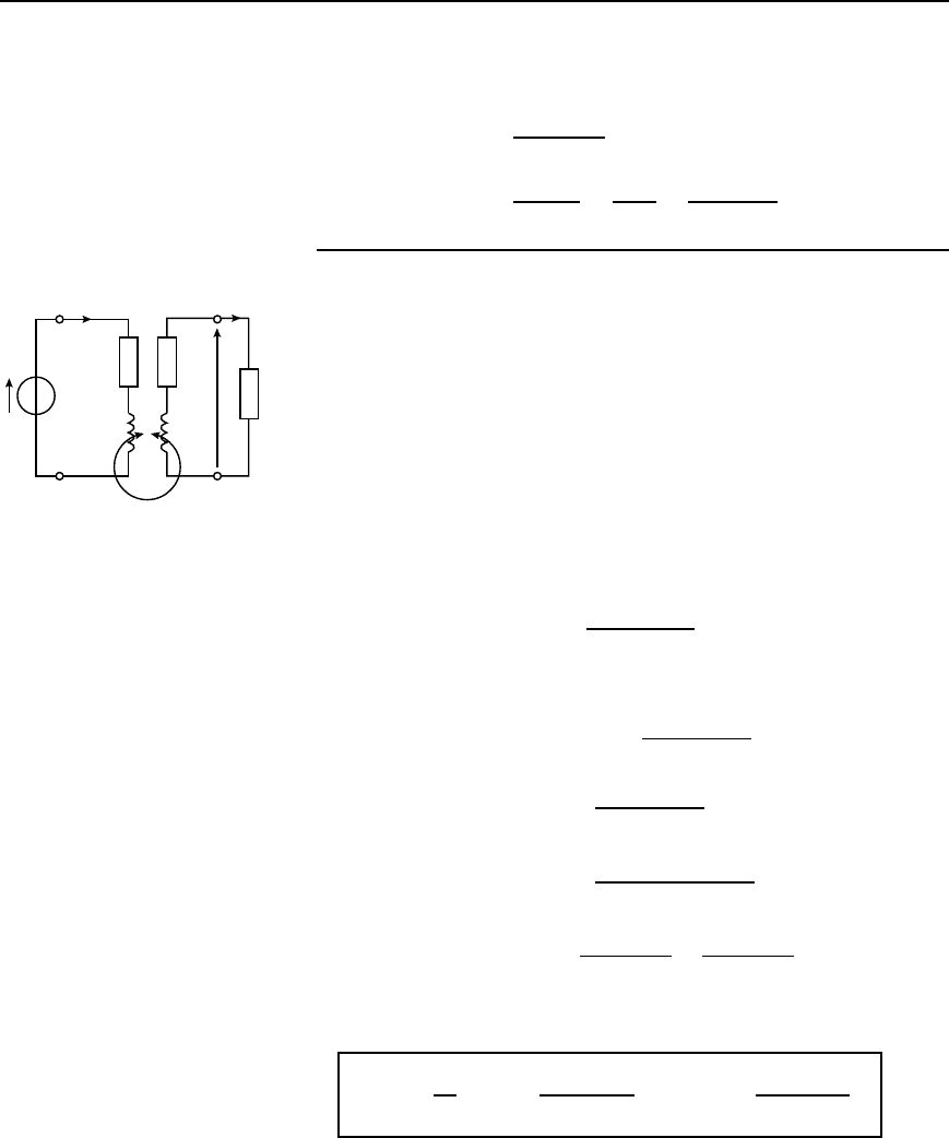
Problem 8. For the circuit shown in Figure 43.7, determine the
p.d. E
2
which appears across the open-circuited secondary winding,
given that E
1
D 8sin2500t volts.
Impedance of primary, Z
1
D R
1
C jωL
1
D 15 Cj25005 ð 10
3
D 15 C j12.5 or 19.53
6
39.81
°
Primary current I
1
D
E
1
Z
1
D
8
6
0
°
19.53
6
39.81
°
I
1
E
1
15 Ω 15 Ω
E
2
5 mH 5 mH
M = 0.1 mH
Figure 43.7
From equation (43.18),
E
2
D jωMI
1
D
jωME
1
R
1
C jωL
1
D
j25000.1 ð 10
3
8
6
0
°
19.53
6
39.81
°
D
2
6
90
°
19.53
6
39.81
°
D 0.102
66
50.19
°
V
Problem 9. Two coils x and y, with negligible resistance, have self
inductances of 20 mH and 80 mH respectively, and the coefficient
of coupling between them is 0.75. If a sinusoidal alternating p.d.
of 5 V is applied to x, determine the magnitude of the open circuit
e.m.f. induced in y.
From equation (43.9), mutual inductance,
M D k
L
x
L
y
D 0.75
[20 ð 10
3
80 ð 10
3
] D 0.03 H
Magnetically coupled circuits 851
From equation (43.22), the magnitude of the open circuit e.m.f. induced
in coil y,
jE
y
jD
jωME
x
R
x
C jωL
x
When R
1
D 0, jE
y
jD
jωME
x
jωL
x
D
ME
x
L
x
D
0.035
20 ð 10
3
D 7.5V
(b) Secondary terminals having load impedance
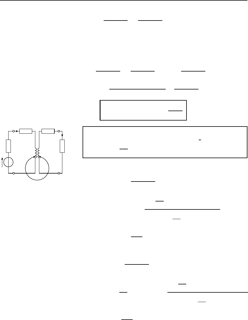
In the circuit shown in Figure 43.8 a load resistor R
L
is connected across
the secondary terminals. Let R
0
2
C R
L
D R
2
When an e.m.f. is induced into the secondary winding a current I
2
flows and this will induce an e.m.f. into the primary winding.
Applying Kirchhoff’s voltage law to the primary winding gives:
E
1
D I
1
R
1
C jωL
1
š jωMI
2
43.23
I
1
E
1
R
1
E
2
L
1
M
L
2
R
2
′
R
L
I
2
Figure 43.8
Applying Kirchhoff’s voltage law to the secondary winding gives:
0 D I
2
R
2
C jωL
2
š jωMI
1
43.24
From equation (43.24), I
2
D
ÝjωI
1
R
2
C jωL
2
Substituting this in equation (43.23) gives:
E
1
D I
1
R
1
C jωL
1
š jωM
ÝjωMI
1
R
2
C jωL
2
i.e., E
1
D I
1
R
1
C jωL
1
C
ω
2
M
2
R
2
C jωL
2
since j
2
D1
D I
1
R
1
C jωL
1
C
ω
2
M
2
R
2
jωL
2
R
2
2
C ω
2
L
2
2
D I
1
R
1
C jωL
1
C
ω
2
M
2
R
2
R
2
2
C ω
2
L
2
2
jω
3
M
2
L
2
R
2
2
C ω
2
L
2
2
The effective primary impedance Z
1eff
of the circuit is given by:
Z
1.eff/
=
E
1
I
1
= R
1
Y
!
2
M
2
R
2
R
2
2
Y !
2
L
2
2
Y j
!L
1
−
!
3
M
2
L
2
R
2
2
Y !
2
L
2
2
43.25
In equation (43.25), the primary impedance is R
1
C jωL
1
. The
remainder,
852 Electrical Circuit Theory and Technology
i.e.,
ω
2
M
2
R
2
R
2
2
C ω
2
L
2
2
j
ω
3
M
2
L
2
R
2
2
C ω
2
L
2
2
is known as the reflected impedance since it represents the impedance
reflected back into the primary side by the presence of the secondary
current.
Hence reflected impedance
D
ω
2
M
2
R
2
R
2
2
C ω
2
L
2
2
j
ω
3
M
2
L
2
R
2
2
C ω
2
L
2
2
D ω
2
M
2
R
2
jωL
2
R
2
2
C ω
2
L
2
2
D ω
2
M
2
R
2
jωL
2
R
2
C jωL
2
R
2
jωL
2
D
ω
2
M
2
R
2
C jωL
2
i.e.,
reflected impedance, Z
r
=
!
2
M
2
Z
2
43.26
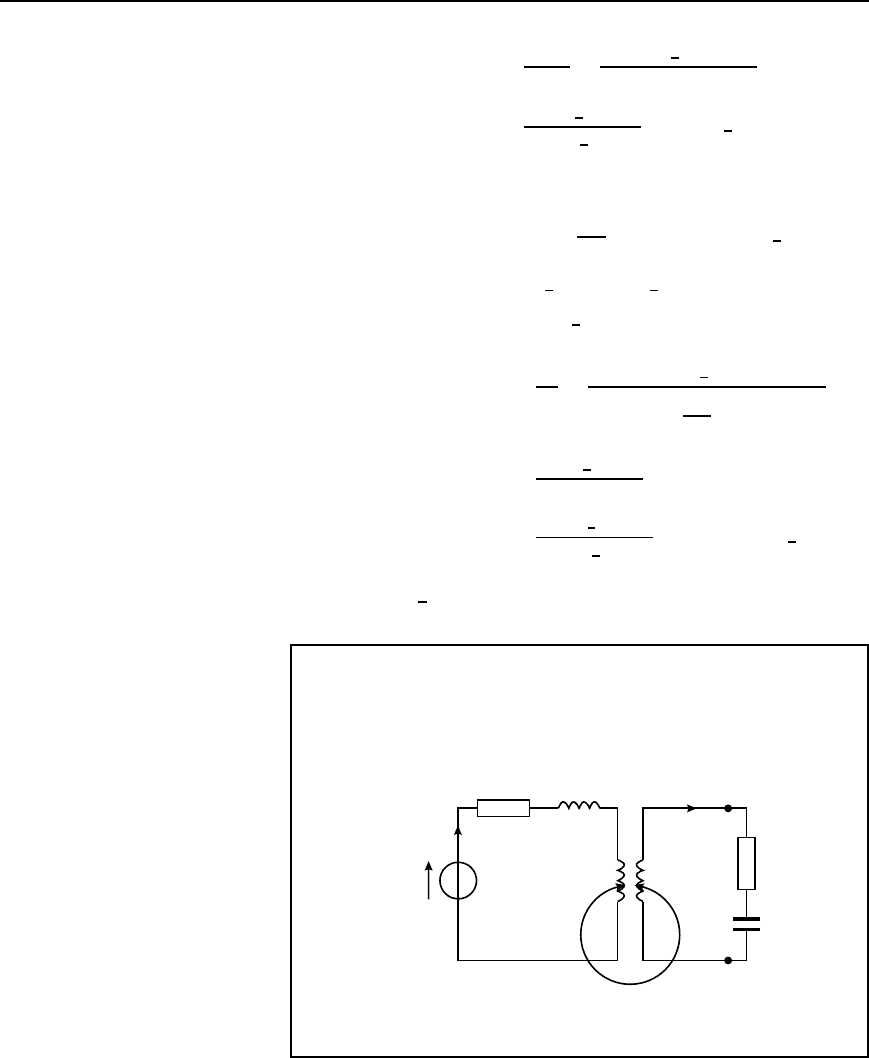
Problem 10. For the circuit shown in Figure 43.9, determine the
value of the secondary current I
2
if E
1
D 2
6
0
°
volts and the
frequency is
10
3
Hz.
I
1
16 Ω 16 Ω
I
2
50 Ω
4 Ω
E
1
10 mH 10 mH
M = 2 mH
Figure 43.9
From equation (43.25), R
1eff
is the real part of Z
1eff
,
i.e., R
1eff
D R
1
C
ω
2
M
2
R
2
R
2
2
C ω
2
L
2
2
D 4 C 16 C
2
10
3
2
2 ð 10
3
2
16 C 50
66
2
C
2
10
3
2
10 ð 10
3
2
D 20 C
1056
4756
D 20.222
and X
1eff
is the imaginary part of Z
1eff
, i.e.,
X
1eff
D ωL
1
ω
3
M
2
L
2
R
2
2
C ω
2
L
2
2
D
2
10
3
10 ð 10
3
2
10
3
3
2 ð 10
3
2
10 ð 10
3
66
2
C
2
10
3
2
10 ð 10
3
2
D 20
320
4756
D 19.933
Magnetically coupled circuits 853
Hence primary current, I
1
D
E
1
Z
1eff
D
2
6
0
°
20.222 C j19.933
D
2
6
0
°
28.395
6
44.59
°
D 0.0704
6
44.59
°
A
From equation (43.18), E
2
D jωMI
1
D j
2
10
3
2 ð 10
3
0.0704
6
44.59
°
D 4
6
90
°
0.0704
6
44.59
°
D 0.282
6
45.41
°
V
Hence secondary current I
2
D
E
2
Z
2
D
0.282
6
45.41
°
66 C j
2
10
3
10 ð 10
3
D
0.282
6
45.41
°
66 C j20
D
0.282
6
45.41
°
68.964
6
16.86
°
D 4.089 ð 10
3
6
28.55
°
A
i.e., I
2
= 4.09
66
28.55
°
mA
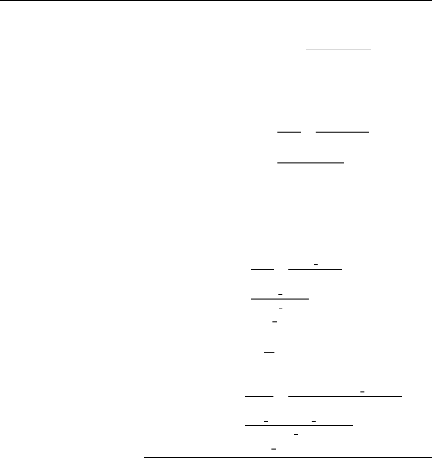
Problem 11. For the coupled circuit shown in Figure 43.10,
calculate (a) the self impedance of the primary circuit, (b) the self
impedance of the secondary circuit, (c) the impedance reflected into
the primary circuit, (d) the effective primary impedance, (e) the
primary current, and (f) the secondary current.
I
1
300 Ω
0.2 H
50∠0° V
w = 500 rad/s
0.5 H 0.3 H
I
2
500 Ω
5 µF
M = 0.2 H
Figure 43.10
(a) Self impedance of primary circuit, Z
1
D 300 C j5000.2 C 0.5
i.e., Z
1
= .300 Y j350/Z
854 Electrical Circuit Theory and Technology
(b) Self impedance of secondary circuit,
Z
2
D 500 C j
5000.3
1
5005 ð 10
6
D 500 C j150 400
i.e., Z
2
= .500 − j250/Z
(c) From equation (43.26),
reflected impedance, Z
r
D
ω
2
M
2
Z
2
D
500
2
0.2
2
500 j250
D
10
4
500 C j250
500
2
C 250
2
D .16 Y j8/Z
(d) Effective primary impedance,
Z
1eff
D Z
1
C Z
r
(note this is equivalent to equation 43.25)
D 300 C j350 C 16 Cj8
i.e., Z
1.eff/
= .316 Y j358/Z
(e) Primary current I
1
D
E
1
Z
1eff
D
50
6
0
°
316 C j358
D
50
6
0
°
477.51
6
48.57
°
D 0.105
66
−48.57
°
A
(f) Secondary current, I
2
D
E
2
Z
2
, where
E
2
D jωMI
1
from equation (43.18)
Hence I
2
D
jωMI
1
Z
2
D
j5000.20.105
6
48.57
°
500 j250
D
100
6
90
°
0.105
6
48.57
°
559.02
6
26.57
°
D 0.0188
66
68
°
A
(c) Resonance by tuning capacitors
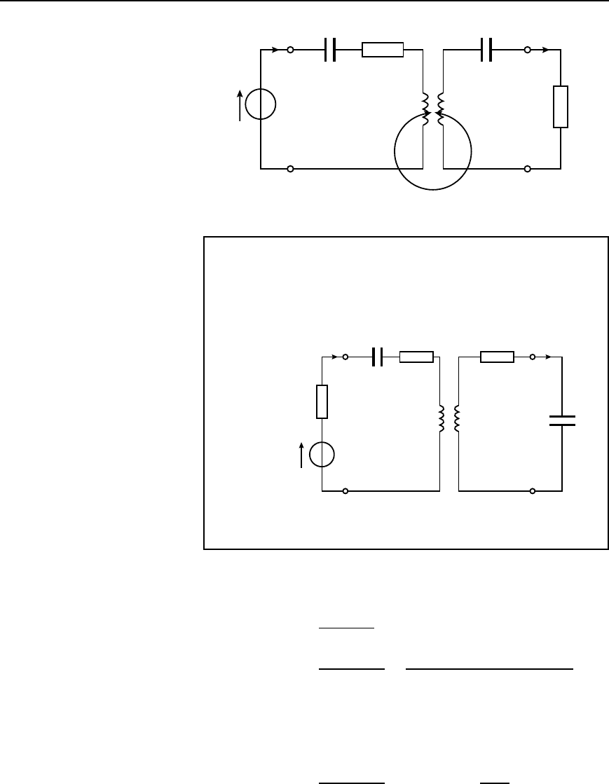
Tuning capacitors may be added to the primary and/or secondary circuits
to cause it to resonate at particular frequencies. These may be connected
either in series or in parallel with the windings. Figure 43.11 shows each
winding tuned by series-connected capacitors C
1
and C
2
. The expres-
sion for the effective primary impedance Z
1eff
, i.e., equation (43.25)
applies except that ωL
1
becomes ωL
1
1/ωC
1
and ωL
2
becomes
ωL
2
1/ωC
2
Magnetically coupled circuits 855
I
1
C
1
R
1
L
1
L
2
C
2
I
2
E
1
R
2
M
Figure 43.11
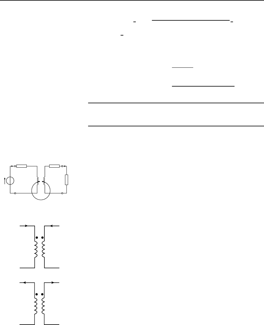
Problem 12. For the circuit shown in Figure 43.12 each winding
is tuned to resonate at the same frequency. Determine (a) the reso-
nant frequency, (b) the value of capacitor C
2
, (c) the effective
primary impedance, (d) the primary current, (e) the voltage across
capacitor C
2
and (f) the coefficient of coupling.
I
1
400 pF
30 Ω
1 mH 0.2 mH
50 Ω
I
2
C
2
15 Ω
M = 10 µH
E
1
= 20∠0° V
Figure 43.12
(a) For resonance in a series circuit, the resonant frequency, f
r
,is
given by:
f
r
D
1
2
p
LC
Hz
Hence f
r
D
1
2
p
L
1
C
1
D
1
2
1 ð 10
3
400 ð 10
12
D 251.65 kHz
(b) The secondary is also tuned to a resonant frequency of 251.65 kHz.
Hence f
r
D
1
2
p
L
2
C
2
i.e., 2f
r
2
D
1
L
2
C
2

856 Electrical Circuit Theory and Technology
and capacitance, C
2
D
1
L
2
2f
r
2
D
1
0.2 ð 10
3
[2251.65 ð 10
3
]
2
D 2.0 ð 10
9
For2.0nF
(Note that since f
r
D
1
2
p
L
1
C
1
D
1
2
p
L
2
C
2
then L
1
C
1
D L
2
C
2
and C
2
D
L
1
C
1
L
2
D
1 ð 10
3
400 ð 10
12
0.2 ð 10
3
D 2.0 nF)
(c) Since both the primary and secondary circuits are resonant, the effec-
tive primary impedance Z
1eff
, from equation (43.25) is resistive,
i.e., Z
1.eff/
D R
1
C
ω
2
M
2
R
2
R
2
2
C
ωL
1
1
ωC
1
2
D R
1
C
ω
2
M
2
R
2
R
2
2
D R
1
C
ω
2
M
2
R
2
D 15 C 30
C
[2251.65 ð 10
3
]
2
10 ð 10
6
2
50
D 45 C 5 D 50 Z
(d) Primary current, I
1
D
E
1
Z
1eff
D
20
6
0
°
50
D 0.40
66
0
°
A
(e) From equation (43.18), secondary voltage
E
2
D jωMI
1
D j2251.65 ð 10
3
10 ð 10
6
0.40
6
0
°
D 6.325
6
90
°
V
Secondary current, I
2
D
E
2
Z
2
D
6.325
6
90
°
50
6
0
°
D 0.1265
6
90
°
A
Hence voltage across capacitor C
2
D I
2
X
C
2
D I
2
1
ωC
2
Magnetically coupled circuits 857
D 0.1265
6
90
°
1
[2251.65 ð 10
3
]2.0 ð 10
9
6
90
°
D 40
66
0
°
V
(f) From equation (43.10), the
coefficient of coupling, k D
M
p
L
1
L
2
D
10 ð 10
6
1 ð 10
3
0.2 ð 10
3
D 0.0224
Further problem on coupled circuits may be found in Section 43.8,
problems 12 to 16, page 866.
43.7 Dot rule for coupled
circuits
Applying Kirchhoff’s voltage law to each mesh of the circuit shown in
Figure 43.13 gives:
E
1
D I
1
R
1
C jωL
1
š jωMI
2
and 0 D I
2
R
2
C R
L
C jωL
2
š jωMI
1
In these equations the ‘M’ terms have been written as š because it is
not possible to state whether the magnetomotive forces due to currents
I
1
and I
2
are added or subtracted. To make this clearer a dot nota-
tion is used whereby the polarity of the induced e.m.f. due to mutual
inductance is identified by placing a dot on the diagram adjacent to that
end of each equivalent winding which bears the same relationship to the
magnetic flux.
I
1
R
1
I
2
R
2
L
1
L
2
R
L
E
1
M
Figure 43.13
The dot rule determines the sign of the voltage of mutual inductance
in the Kirchhoff’s law equations shown above, and states:
(i) when both currents enter, or both currents leave, a pair of coupled
coils at the dotted terminals, the signs of the ‘M’ terms will be the
same as the signs of the ‘L’ terms, or
(ii) when one current enters at a dotted terminal and one leaves by a
dotted terminal, the signs of the ‘M’ terms are opposite to the signs
of the ‘L’ terms.
Thus Figure 43.14 shows two cases in which the signs of M and L are
the same, and Figure 43.15 shows two cases where the signs of M and
L are opposite. In Figure 43.13, therefore, if dots had been placed at
the top end of coils L
1
and L
2
then the terms jωMI
2
and jωMI
1
in
the Kirchhoff’s equation would be negative (since current directions are
similar to Figure 43.15(a)).
(a)
(b)
Figure 43.14
